
Related Manuals for ADLINK Technology VPX3010 Series


Summary of Contents for ADLINK Technology VPX3010 Series
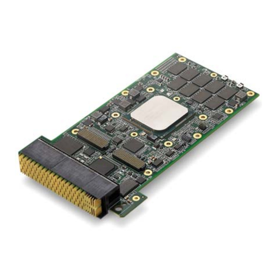
- Page 1 VPX3010 Series Performance Rugged Conduction Cooled ® ® 3U VPX Intel Xeon Processor D-1500 Processor Blade 0.10 Manual Rev.: January 25, 2017 Revision Date: 50-15107-2000 Part No: Advance Technologies; Automate the World.
- Page 2 Revision History Revision Release Date Description of Change(s) 0.10 2017/01/25 Preliminary release...
-
Page 3: Preface
VPX3010 Preface Copyright 2017 ADLINK Technology Inc. This document contains proprietary information protected by copy- right. All rights are reserved. No part of this manual may be repro- duced by any mechanical, electronic, or other means in any form without prior written permission of the manufacturer. - Page 4 Conventions Take note of the following conventions used throughout this manual to make sure that users perform certain tasks and instructions properly. Additional information, aids, and tips that help users perform tasks. NOTE: NOTE: Information to prevent minor physical injury, component dam- age, data loss, and/or program corruption when trying to com- plete a task.
-
Page 5: Table Of Contents
VPX3010 Table of Contents Revision History..............ii Preface ..................iii List of Figures ............... vii List of Tables................ix 1 Introduction ................ 1 Overview................1 Features................3 Block Diagrams..............5 Model Number Decoder - Processor Blade ......6 Package Contents ............... 8 2 Specifications .............. - Page 6 3.12 UART NCT5104..............23 3.13 TPM AT97SC3204............. 23 3.14 XMC Site................24 4 VPX3010 Board Interfaces ..........25 VPX3010 Board Layout ............. 25 VPX3010 Mechanical Drawing .......... 26 VPX3010 Connector Pin Assignments ......27 Switches and LEDs............33 5 VPX-R3010 RTM ..............35 Connector Allocation............
-
Page 7: List Of Figures
VPX3010 List of Figures Figure 1-1: VPX3010 Functional Block Diagram........ 5 Figure 4-1: VPX3010 Component Side Layout ........ 25 Figure 4-2: VPX3010 Component Side Layout ........ 25 Figure 4-3: VPX3010 Mechanical Dimensions......... 26 Figure 4-4: VPX3010 Front View ............. 33 Figure 4-5: VPX3010 Switches and LEDs solder side. - Page 8 This page intentionally left blank. viii List of Figures...
-
Page 9: List Of Tables
VPX3010 List of Tables Table 1-1: VPX3010 SKU Table ............7 Table 2-1: VPX3010 Blade Specifications ........9 Table 2-2: VPX-R3010 RTM Specifications........12 List of Tables... - Page 10 This page intentionally left blank. List of Tables...
-
Page 11: Introduction
VPX3010 Introduction 1.1 Overview The VPX3010 Series is a 3U VPX processor blade based on the Intel® Xeon® Processor D-1500 Family on 14nm silicon technol- ogy and integrating the CPU and chipset in a single sys- tem-on-chip (SoC). The VPX3010 is available with three different eTMP processors: D-1559 (12 cores, 1.5GHz, TDP 45W), D-1539... - Page 12 A VPX-R3010 Rear Transition Module is available to access rear I/O signals for users to validate VPX3010 functionality. The VPX3010 Series is available in a rugged conduction cooled version with conformal coating and an air cooled version to meet different application needs. The rugged conduction cooled version is ideal for mission critical applications in radar;...
-
Page 13: Features
VPX3010 1.2 Features 3U VPX VITA 46, OpenVPX VITA 65, VPX REDI 48 1" rugged conduction cooled and air cooled 3U VPX blade with conformal coating 14nm uFC-BGA Intel® Xeon® Processor D-1500 family Intel® Xeon® processor D-1559, 12-core, 18M Cache, 1.50/1.8 GHz, 45W TDP, -40°C to 85°C Intel®... - Page 14 ABSDiag self-diagnosis tool MOD3-PAY-2F2T-16.2.5-3 or MOD3-PAY-2F2U-16.2.3-3 (BOM option) Slot Profile: SLT3-PAY-2F2U-14.2.5 or SLT3-PAY-2F2U-14.2.3 (BOM option) Introduction...
-
Page 15: Block Diagrams
VPX3010 1.3 Block Diagrams NAND Flash DDR4 DDR4 SATA 6Gb/s BIOS_0 BIOS_1 Intel Xeon Processor D SPI Flash ® ® IPMC COM IC 2x 1000BASE-T RS-232/ *PCIe x8 PCIe x1 SMBus PCIe x4 Gen2 RS422 Gen3 Gen2 1x1000BASE-T + PCIe x1 1x USB 2.0 2x 1000BASE-BX Gen3... -
Page 16: Model Number Decoder - Processor Blade
Model Number Decoder - Processor Blade VPX3010/1559/M16/S32/XMC-R2 (A) CPU Code D-1559 = Intel® processor D-1559, 12 cores, TDP 45W, 1.5GHz D-1539 = Intel® processor D-1539, 8 cores, TDP 35W, 1.6GHz D-1519 = Intel® processor D-1519, 4 cores, TDP 25W, 1.5GHz (B) Memory Size Code M8 = 8GB DDR4-2133 ECC soldered SDRAM M16 = 16GB DDR4-2133 ECC soldered SDRAM... - Page 17 VPX3010 VPX3010 SKU Table XMC Version “No XMC” BOM Option Item Description Description PCIe x8 Gen3 with Rear IO to P2w7-X8d+X12d 1x 1000BASE-T + 2x 1000BASE-BX 2x 1000BASE-T to P1 to P1 Ethernet 2x 10GBASE-KR to P2 2x 10GBASE-KR to P2 PCIe x8 Gen3 to P1 (or 2 x4 or 1 PCIe x8 Gen3 to P1 (or 2 x4 or 1 x8) x8) to P1 with NTB-LAN 0 to LAN 3...
-
Page 18: Package Contents
1.5 Package Contents The VPX3010 is packaged with the following components. If any of the items on the contents list are missing or damaged, retain the shipping carton and packing material and contact the dealer for inspection. Please obtain authorization before returning any prod- uct to ADLINK. -
Page 19: Specifications
VPX3010 Specifications 2.1 VPX3010 Blade Specifications VITA Standards • VITA 46.0 VPX Base Standard • VITA 46.4 PCI Express on VPX Fabric Connector • VITA 46.6 Gigabit Ethernet Control Plane on VPX • VITA 46.9 PMC/XMC/Ethernet Signal Mapping to 3U/6U •... - Page 20 • SATA 6Gb/s port 0 to P1 SATA • SATA 6Gb/s port 1 to SATA 3Gb/s NAND SLC flash, 32GB (64GB optional) • SATA 6Gb/s port 2 to P2 (“no XMC” BOM option only) • Silicon Motion SM750 2D graphics chip via PCIe x1 with Graphics VGA output to P2 •...
- Page 21 VPX3010 Environmental • Operating Temperature Conduction Cooled: R0: 0°C to +50°C at card edge R1: -40°C to +75°C at card edge R2: -40°C to +85°C at card edge Air Cooled: A0: 0°C to +50°C at card edge A1: -40°C to +75°C at card edge •...
-
Page 22: Vpx-R3010 Rtm Specifications
2.2 VPX-R3010 RTM Specifications • 2x 1000BASE-BX via RP1 (Molex 74703-0017) Ethernet • 2x 1000BASE-T via RP1 (Standard RJ-45 connector) • 2x SFP+ connector via RP1 • 1x VGA signal via RP2 (Standard DB15 connector) Graphics • 2x SATA via RP2 (7 pin vertical SATA connector) SATA •... -
Page 23: Power Consumption
VPX3010 2.3 Power Consumption This section provides information on the power consumption of the VPX3010 Series when using Intel® D-1559/D-1539/D-1519 processors with Dual Chan- nel 16GB DDR4-2133 soldered memory and soldered onboard SATA SSD. The VPX3010 is powered by 12V, 5V and 3.3V. Power consumption at 100% CPU usage was measured by running BurnInTest and Intel Thermal Analysis Tool (TAT). - Page 24 Xeon® D-1559 (18M Xeon® D-1539 (12M Intel® D-1519 (6M Processor Cache, 1.50 GHz) Cache, 1.60 GHz) Cache, 1.50GHz) Windows Typical mode/Disable EIST 3.3V (A) 1.31 1.28 5V (A) 0.83 0.86 0.81 12V (A) 2.69 2.03 5VSB(A) Power 52.84 40.903 32.634 Consumption (W) Windows MAX mode/Enable EIST Package Power...
- Page 25 VPX3010 Xeon® D-1559 (18M Xeon® D-1539 (12M Intel® D-1519 (6M Processor Cache, 1.50 GHz) Cache, 1.60 GHz) Cache, 1.50GHz) 3.3V (A) 1.28 5V (A) 0.91 0.93 0.88 12V (A) 3.42 2.67 5VSB(A) Power 65.24 49.98 40.664 Consumption (W) *Windows 7 (Typical) power consumption running BurnInTest at 100% loading.
- Page 26 This page intentionally left blank. Specifications...
-
Page 27: Functional Description
VPX3010 Functional Description The following sections describe the VPX3010 features and functions. 3.1 Processors The Intel® Xeon® Processor D-1500 family is the first Intel® Xeon® SoC based on 14nm silicon technology and addresses a broad range of low-power, high-density application needs. The SoC has an integrated platform controller hub (PCH), integrated I/O, two integrated 10 Gigabit Intel®... - Page 28 Supported Technologies Intel® Virtualization Technology for Directed I/O (Intel® VT-d) Intel® Virtualization Technology (Intel® VT-x) Intel® VT-x with Extended Page Tables (EPT) Intel® Hyper-Threading Technology Intel® 64 Architecture Execute Disable Bit Intel® Turbo Boost Technology 2.0 Intel® TSX-NI Enhanced Intel SpeedStep® Technology Thermal Monitoring Technologies Features 1.5MB L3 cache per core in BGA packages...
- Page 29 VPX3010 Interfaces Dual channel DDR4 memory with two channel of soldered SDRAM Memory DDR4 data transfer rates of 2133 MT/s 64-bit wide channels plus 8-bits of ECC support for each channel System Memory Interface I/O Voltage of 1.2V 8-Gb DDR4 DRAM technologies supported The PCI Express lanes are fully-compliant with the PCI Express Base Specification, Revision 3.0, including support for 8.0 GT/s transfer speeds.
-
Page 30: Intel® Turbo Boost Technology
3.2 Intel® Turbo Boost Technology Intel Turbo Boost Technology is a feature that allows the processor to opportunistically and automatically run faster than its rated operating core and/or render clock frequency when there is suffi- cient power headroom, and the product is within specified temper- ature and current limits. -
Page 31: Usb
VPX3010 PCH (integrated in processor) PCI Express Base Specification, Revision 2.0 support for up to eight ports with transfers up to 5GT/s. Enhanced DMA controller, interrupt controller and timer functions Integrated Serial ATA host controller with independent DMA operation on up to three ports. xHCI USB controller provides support for up to 3 USB ports, of which four can be configured as USB 3.0 ports (2x USB 3.0 and 1x USB 2.0 implemented on VPX3010) -
Page 32: System Management Bus
3.5 System Management Bus The PCH provides a System Management Bus (SMBus) Specifi- cation Version 2.0 compliant Host Controller as well as an SMBus Slave Interface. The PCH provides a mechanism for the processor to initiate communications with SMBus peripherals (slaves) as well as I2C compatible devices. -
Page 33: Graphics
VPX3010 3.10 Graphics The SM750 is designed to complement needs for the embedded industry and provides video and 2D capability. 3.11 GPIO Expander PCA9554 The PCA9554 is16-pin CMOS devices that provide 8 bits of Gen- eral Purpose parallel input/output (GPIO) expansion I2C/SMBus applications 3.12 UART NCT5104... -
Page 34: Xmc Site
3.14 XMC Site The VPX3010 Series supports one XMC site for rear I/O expan- sion. The XMC site provides a x8 PCI Express Gen 3.0 lane. Jn2 rear XMC I/O connector is compliant to VITA 46.9, X8d+X12d. Functional Description... -
Page 35: Vpx3010 Board Interfaces
VPX3010 VPX3010 Board Interfaces This chapter illustrates the board layout, connector pin assign- ments, and jumper settings to familiarize users with the VPX3010. 4.1 VPX3010 Board Layout Figure 4-1: VPX3010 Component Side Layout Figure 4-2: VPX3010 Component Side Layout VPX3010 Board Interfaces... -
Page 36: Vpx3010 Mechanical Drawing
4.2 VPX3010 Mechanical Drawing Conduction Cooled Air Cooled Dimensions in mm Figure 4-3: VPX3010 Mechanical Dimensions VPX3010 Board Interfaces... -
Page 37: Vpx3010 Connector Pin Assignments
VPX3010 4.3 VPX3010 Connector Pin Assignments XMC Connectors JN1 Connector PCIE_RX8_P PCIE_RX8_N 3.3V PCIE_RX9_P PCIE_RX9_N VPWR NC(PU to 3.3V) MRSTI# PCIE_RX10_P PCIE_RX10_N 3.3V PCIE_RX11_P PCIE_RX11_N VPWR NC(PD to MRSTO# GND) PCIE_RX12_P PCIE_RX12_N 3.3V PCIE_RX13_P PCIE_RX13_N VPWR NC(PU to 3.3V) 12V_AUX PCIE_RX14_P PCIE_RX14_N 3.3V... - Page 38 JN2 Connector JN6-A1 JN6-B1 JN6-D1 JN6-E1 JN6-A3 JN6-B3 JN6-D3 JN6-E3 JN6-A5 JN6-B5 JN6-D5 JN6-E5 JN6-A7 JN6-B7 JN6-D7 JN6-E7 JN6-A9 JN6-B9 JN6-D9 JN6-E9 JN6-A11 JN6-B11 JN6-D11 JN6-E11 JN6-A13 JN6-B13 JN6-D13 JN6-E13 JN6-A15 JN6-B15 JN6-D15 JN6-E15 JN6-A17 JN6-B17 JN6-D17 JN6-E17 JN6-A19 JN6-B19 JN6-D19 JN6-E19 VPX3010 Board Interfaces...
- Page 39 VPX3010 VPX Connectors P0 Connector 3.3V 3.3V 3.3V 3.3V 3.3V 3.3V IPM1_CLK IPM1_DAT N12V_AUX SYSRESET# NVMRO 3.3V_AUX IPM2_CLK IPM2_DAT P12V_AUX IPMB_ IPMB_ IPMB_ IPMB_ IPMB_ JTCK JTDO JTDI JTMS JTRST-L H_CLK_P0_ H_CLK_P0_ REF_CLK- REF_CLK+ 100M_N/ 100M_P/ RES_BUS+ RES_BUS+ VPX3010 Board Interfaces...
- Page 40 P1 Connector Type COM1_RTS#/ L0-TX- L0-TX+ L0-RX- L0-RX+ GPIO0 L1-TX- L1-TX+ L1-RX- L1-RX+ P1_VBAT L2-TX- L2-TX+ L2-RX- L2-RX+ L3-TX- L3-TX+ L3-RX- L3-RX+ SYSCON# L4-TX- L4-TX+ L4-RX- L4-RX+ L5-TX- L5-TX+ L5-RX- L5-RX+ COM1_CTS#/ L6-TX- L6-TX+ L6-RX- L6-RX+ GPIO1 L7-TX- L7-TX+ L7-RX- L7-RX+ COM1_TXD SATA0-TX- SATA0_TX+...
- Page 41 VPX3010 P2 Connector (XMC version) Type COM2_RTS#/ 10GKR_TX0 10GKR_TX0 10GKR_RX0 10GKR_RX0 GPIO4 _L0- _L0+ _L0- _L0+ 10GKR_TX0 10GKR_TX0 10GKR_ 10GKR_RX0 _L1- _L1+ RX0_L1- _L1+ DDC_DATA USB3_RX- USB3_RX+ USB3_TX- USB3_TX+ USB2_0 +5V_USB_2 +5V_USB_2 USB2_0+ COM2_DCD COM2_RXD (RS422_TX-) (RS422_TX+) COM2_DTR# COM2_TXD DDC_CLK (RS485_TX/ (RS485_TX/ (RS422_RX-)
- Page 42 P2 Connector (“no XMC” BOM options version) Type 10GKR_TX0 10GKR_TX0 10GKR_RX 10GKR_RX0 COM2_RTS#/ _L0- _L0+ 0_L0- _L0+ GPIO4 10GKR_TX0_ 10GKR_TX0 10GKR_ 10GKR_RX _L1+ RX0_L1- 0_L1+ DDC_DATA USB3_RX- USB3_RX+ USB3_TX- USB3_TX+ USB2_0 +5V_USB_2 +5V_USB_2 USB2_0+ COM2_DCD COM2_RXD (RS422_TX-) (RS422_TX+) COM2_DTR# COM2_TXD DDC_CLK (RS485_TX/ (RS485_TX/...
-
Page 43: Switches And Leds
VPX3010 4.4 Switches and LEDs LED2 LED1 LED3 LED4 Figure 4-4: VPX3010 Front View LED3 LED4 Figure 4-5: VPX3010 Switches and LEDs solder side. ME mode switch Reset button Power LED Reset LED LED1 LED3 SATA LED BIOS Selection LED LED2 LED4 VPX3010 Board Interfaces... - Page 44 ME Mode Switch (SW4) Pin 1 Pin 2 ME Mode (MFG_MODE_STRAP) (Reserved) Manufacture Mode Normal Mode Reset Button (SW5) Press this button to perform a hard system reset. LEDs Description Indication LED1 Power LED On when blade is receiving power LED2 SATA LED Blinks when SATA is active...
-
Page 45: Vpx-R3010 Rtm
VPX3010 VPX-R3010 RTM This chapter illustrates the board layout, connector pin assign- ments, and jumper settings to familiarize users with the VPX-R3010 RTM. Connector Allocation VPX-R3010 Function Rear I/O RPx Top Side RPx Connector Type VGA standard — — connector; DB15 SerDes-1000BASE-BX —... - Page 46 VPX-R3010L2 Function Rear I/O Top Side Connector Type PCIe x16 RP1/ — — Standard PCIe x16 slot PCIe x1 — — Standard PCIe x1 slot VPX-R3010L2-1 Function Rear I/O Top Side Connector Type 10G-KR — — Standard SFP+ connector VPX-R3010 RTM...
-
Page 47: Vpx-R3010 Block Diagram
VPX3010 5.2 VPX-R3010 Block Diagram Figure 5-1: VPX-R3010 RTM Functional Block Diagram VPX-R3010 RTM... -
Page 48: Vpx-R3010 Rtm Board Layout
5.3 VPX-R3010 RTM Board Layout Board-to-Board GPI0 Connector Header USB 2.0 Header Alignment COM0 Header SMBus Connector COM1 Header 8x LEDs for GPIO JTAG USB 3.0 SATA Connectors 1000BASE-T 1000BASE-T Alignment 3.3V Top View 1000BASE-BX USB 3.0 1000BASE-BX Rear View Figure 5-2: VPX-R3010 RTM Board Layout VPX-R3010 RTM... -
Page 49: Figure 5-3: Vpx-R3010 Solder Side Layout
VPX3010 SW_IPMB1 SW_GPIO1 SW_GPIO2 Solder Side View Figure 5-3: VPX-R3010 Solder Side Layout VPX-R3010 RTM... -
Page 50: Figure 5-4: Vpx-R3010-L2 Board Layout
PCIe x1 slot PCIe x16 slot Figure 5-4: VPX-R3010-L2 Board Layout 10G SFP+ Connector 10G SFP+ Connector Figure 5-5: VPX-R3010-L2-1 Board Layout VPX-R3010 RTM... -
Page 51: Vpx-R3010 Rtm Connector Pin Assignments
VPX3010 5.4 VPX-R3010 RTM Connector Pin Assignments Rear I/O Connectors VGA Connector Signal Name Pin # Pin # Signal Name Green Blue N.C. +5V. N.C. CRTDATA HSYNC VSYNC CRTCLK 1000BASE-BX Connectors Pin # GbE Signal GND1 TP2_R TN2_R GND2 RN2_R RP2_R GND3 VPX-R3010 RTM... - Page 52 USB 3.0 Connectors Pin # Signal Name USB3.0_P5VA USB2_CMAN USB2_CMAP USB3A_CMRXN USB3A_CMRXP USB3A_CMTXN USB3A_CMTXP VPX-R3010 RTM...
- Page 53 VPX3010 SFP+ 10Gigabit Ethernet Connector (VPX-R3010-L2-1) Pin # 1000BASE-T SFP_TX_FAULT SFP_TX_DISABLE SFP_SDA SFP_SCL SFP_MOD_ABS SFP_RX_LOS SRDS_RX-N SRDS_RX-P SFP_V3P3_R SFP_V3P3_T SRDS_TX-P SRDS_TX-N VPX-R3010 RTM...
- Page 54 Onboard Connectors 1000BASE-T (RJ-45) Pin # Signal MX0+ MX0- MX1+ MX2+ MX2- MX1- MX3+ MX3- RS-232 Header (COM0/COM1) RS-422/485 RS-485 Pin # RS-232 full duplex half duplex (COM1 only) (COM1 only) DCD# TXD- TX/RX+ DSR# TXD+ TX/RX- RXD+ RXD- COM1 mode by BIOS setting. NOTE: NOTE: RS-232 supports Tx/Rx only on “no XMC”...
- Page 55 VPX3010 JTAG Header Pin # Signal +3.3V TRST +3.3V USB 2.0 Connector Pin # Signal VPX-R3010 RTM...
- Page 56 SATA Connectors Pin # Signal SMBus (SM1) Pin # Signal IPMB_SDA IPMB_SCL GPIO Header (GPIO1) Pin # Signal GPI4 GPI0 GPI5 GPI1 GPI6 GPI2 GPI7 GPI03 VPX-R3010 RTM...
- Page 57 VPX3010 GPIO LEDs LED # Signal LED1 GPIO0 LED2 GPIO1 LED3 GPIO2 LED4 GPIO3 LED5 GPIO4 LED6 GPIO5 LED7 GPIO6 LED8 GPIO7 VPX-R3010 RTM...
-
Page 58: Vpx-R3010 Switches
5.5 VPX-R3010 Switches IPMB Switch (SW_IPMB1) Pin Settings Function All ON Enable IPMI All OFF Disable IPMI GPIO/COM Switches (SW_GPIO1, SW_GPIO2) These switches route the signals from the VPX3010 processor blade to the correct onboard connectors depending on which version is being used. Make sure the switch settings corre- spond to those below for the VPX3010 version you are using (XMC version or “no XMC”... -
Page 59: Important Safety Instructions
VPX3010 Important Safety Instructions For user safety, please read and follow all instructions , WARNINGS , CAUTIONS, and NOTES marked in this manual and on the associated equipment before handling/operating the equipment. Read these safety instructions carefully. Keep this user’s manual for future reference. Read the specifications section of this manual for detailed information on the operating environment of this equipment. - Page 60 Never attempt to fix the equipment. Equipment should only be serviced by qualified personnel. A Lithium-type battery may be provided for uninterrupted, backup or emergency power. Risk of explosion if battery is replaced with one of an incorrect type. Dispose of used batteries appropriately. WARNING: Equipment must be serviced by authorized technicians when:...
-
Page 61: Getting Service
San Jose, CA 95138, USA Tel: +1-408-360-0200 Toll Free: +1-800-966-5200 (USA only) Fax: +1-408-360-0222 Email: info@adlinktech.com ADLINK Technology (China) Co., Ltd. 300 Fang Chun Rd., Zhangjiang Hi-Tech Park Pudong New Area, Shanghai, 201203 China Tel: +86-21-5132-8988 Fax: +86-21-5132-3588 Email: market@adlinktech.com...
Need help?
Do you have a question about the VPX3010 Series and is the answer not in the manual?
Questions and answers