Table of Contents
Advertisement
Advertisement
Table of Contents

Related Manuals for FS S5800 Series


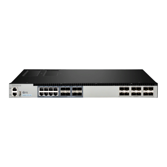
Summary of Contents for FS S5800 Series
- Page 1 N E T W O R K S DATA CENTER SWITCHES USER MANUAL...
-
Page 2: Table Of Contents
Contents Chapter 1 Introduction..............1 Chapter 2 Mounting the Switch............2.1 Environmental Requirements............2.2 Rack-Mount Installation.............. 2.3 Install the Switch on a Workbench..........Chapter 3 Configuring the Switch..........3.1 Building Configuration Platform and Connecting Cable....3.2 Setting Terminal Parameter (Windows super terminal)....3.3 Setting Terminal Parameter (SecureCRT from VanDyke Software) Chapter 4 Maintenance and Troubleshooting........ -
Page 3: Chapter 1 Introduction
CAUTION: No user serviceable parts inside. Must be serviced by technically qualified personnel. This User Manual will familiarize you with the layout of the N-series Cumulus Linux switches and describe how to deploy the device in your network. For additional information, see www.fs.com. Data Center, Enterprise & ISP Network Solutions... -
Page 4: Chapter 2 Mounting The Switch
Chapter 2 Mounting the Switch 2.1 Environmental Requirements There are two ways to mount the switch: • Set the switch on a flat surface. • Mount the switch in a standard rack (1 rack unit high). Before you begin installing your switch, prepare the installation site. Make sure your operating environment meets the operating environment requirements of the equipment. -
Page 5: Install The Switch On A Workbench
Step 4: Place switch on the tray horizontally, push it slightly into the rack along the tray, and fix the other end of Front Mounting Brackets upon the front hold strip of rack using screw and its matching floating nut. Figure 2-2 Installation Recommendations: When installing a variety of equipment on the same cabinet, it is recommended to install the... -
Page 6: Chapter 3 Configuring The Switch
There are 4 foot pads that come with the device. Paste them onto the bottom near the corners of the switch, as shown below: Figure 2-3 Chapter 3 Configuring the Switch 3.1 Building Configuration Platform and Connecting Cable Connect DB-9 hole-type plug of configuration cable to the serial port for configuring switch. Connect RJ-45 end of configuration cable to the console port of switch. -
Page 7: Setting Terminal Parameter (Securecrt From Vandyke Software)
Step 3: When the Network Properties dialog box is displayed as shown in following figure. Set Bits per second to 115200, Data bits to 8, Parity to None, Stop bits to 1, and Flow control to None. (In other Windows operating systems, bits per second may be described as baud rate and data stream control may be described as traffic control.) Step 4: Click OK after setting the serial port parameters and input the user name/password: admin/admin, then enter the HyperTerminal window. -
Page 8: Chapter 4 Maintenance And Troubleshooting
Chapter 4 Maintenance and Troubleshooting 4.1 Loading Failure Processing: After loading fails, the system will keep running in the original version. At this time, users should re-check if physical port connections are good firstly. If some ports are not connected, then re-connect them to ensure that physical connections are correct, and begin re-loading. -
Page 9: Configuration System Troubleshooting
4.4 Configuration System Troubleshooting: After the switch is powered on, if system is normal, the startup information will be displayed on the configuration terminal; If the configuration system is faulty, the configuration terminal may display no information or hashes. 4.5 No Information on the Terminal: After power-on, if no display information on configuration terminal appears, please check if: The power is normal. - Page 10 Hardware Warranty Card FS ensures our customers that any damage or faulty items due to our workmanship, we will offer a free return within 30-Days from when you receive your goods. This excludes any custom made items or tailored solutions.
- Page 11 FS offers two channels to process your return request, if you purchase from FS website, you may visit the website and log in to your FS “account “center to start a quick return. If you purchased by emails, you may contact your sales representative or visit our website fs.com to talk with customer service team and obtain an approved Return Materials Authorization (RMA) Number.
Need help?
Do you have a question about the S5800 Series and is the answer not in the manual?
Questions and answers