Sign In
Upload
Download
Table of Contents
Contents
Add to my manuals
Delete from my manuals
Share
URL of this page:
HTML Link:
Bookmark this page
Add
Manual will be automatically added to "My Manuals"
Print this page
×
Bookmark added
×
Added to my manuals
Manuals
Brands
MacDon Manuals
Farm Equipment
912
Operator's manual
MacDon 912 Operator's Manual
Hide thumbs
1
2
3
Table Of Contents
4
5
6
7
8
9
10
11
12
13
14
15
16
17
18
19
20
21
22
23
24
25
26
27
28
29
30
31
32
33
34
35
36
37
38
39
40
41
42
43
44
45
46
47
48
49
50
51
52
53
54
55
56
57
58
59
60
61
62
63
64
65
66
67
68
69
70
71
72
73
74
75
76
77
78
79
80
81
82
83
84
page
of
84
Go
/
84
Contents
Table of Contents
Troubleshooting
Bookmarks
Table of Contents
Introduction
Table of Contents
Serial Number Locations
Safety
Safety Alert Symbol
Signal Words
Safety Signs
General Farm Safety
Specifications
Auger Header and Hay Conditioner
Hardware Torque Specifications
Hydraulic Fittings Torque Specifications
Operation
Your Responsibilities as an Owner/Operator
To the New Operator
Attaching the Hay Conditioner
Detaching the Hay Conditioner
Break-In Period
Pre-Starting Checks: Annual
Pre-Starting Checks: Daily
Operate Correctly
Header Controls
Header Lift Cylinder Stops
Operating Variables
Lean Bar Position
Ground Speed
Reel Speed
Reel Pick-Up Finger Pitch
Cutting Height
Skid Shoes
Gauge Rollers
Header Angle
Header Flotation
Auger Mounted Crop Deflectors/Stripper Bar Extensions/Short Spare Stripper
Hay Conditioner Roll Intermesh
Hay Conditioner Roll Tension Springs
Auger Feed Pan/Rock Drop Tine Position Relative to Hay Conditioner
Hay Conditioner Forming Shields
Windrow Width
Rear Deflector
Forming Shield Height
Forming Shield Deflector Fins
Haying Tips
Topsoil Moisture
Climate and Topography
Windrow Characteristics
Raking and Tedding
Chemical Drying Agents
Grass Seed Special" Header
Unplugging the Header
Hydraulic Conditioner Roll Opener
Transporting the Header
Lifting the Header in Working Position
Storage Procedure
Maintenance/Service
Service Procedures
Recommended Lubricants
Enclosed Drive Lubricant Capacities
Sealed Bearing Installation
Greasing the Header and Hay Conditioner
Sickle and Sickle Drive
Sickle Lubrication
Sickle Removal
Sickle Sections
Head Needle Bearing Installation
Sickle Installation
Sickle Storage (Spare Sickle)
Standard Sickle Guards and Hold-Downs
Hold Downs - Cast (Optional)
Stub Guards and Hold-Downs
Changing Double Sickle Speed
Double Sickle Timing
Tightening Double Sickle Drive Belts
Tightening Single Sickle Drive Belt
Wobble Box Maintenance
Reel and Reel Drive
Reel Position - Fore and Aft
Replacing Reel Fingers - 922 & 933 Headers
Reel Speed - 912 Header
Reel Drive Belt Tension - 912 Header
Reel Drive Chain Tension - 922 & 933 Headers
Hydraulic Reel Drive - 922 & 933 Headers
Auger and Auger Drive Auger Position
Auger Speed
Auger Drive Belt/Chain Tension
Hay Conditioner
Hay Conditioner Roll Timing
Hay Conditioner Drive Belt
Hay Conditioner Gear Case Lubricant
Maintenance Schedule
Maintenance Record
Troubleshooting
Tall Crop Kit
Gauge Rollers
Adjustable Skid Shoes
Replacement Reel Bat Kits
Stub Guards
Conditioned Windrow Side Delivery System
Hydraulic Conditioner Roll Opener
Assembly
Unloading
Index
Advertisement
Quick Links
1
Table of Contents
2
Auger Header and Hay Conditioner
3
Hay Conditioner Roll Intermesh
Download this manual
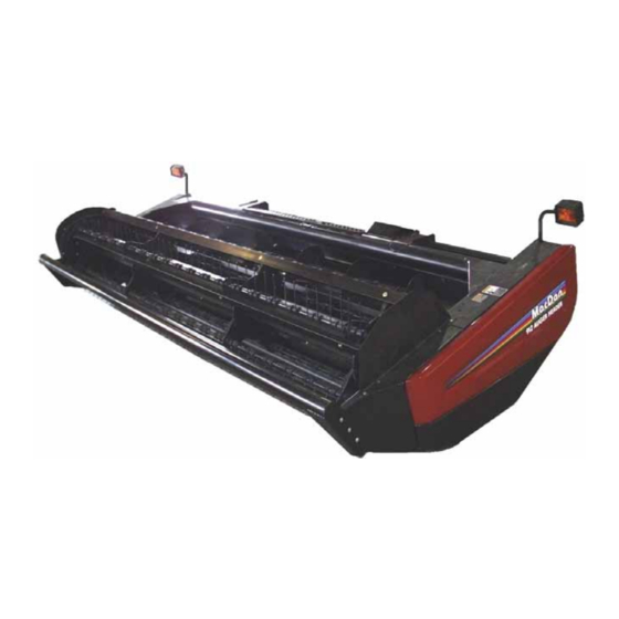
Model 912 / 922
AUGER HEADER and
Model 722
HAY CONDITIONER
Model 933
Grass Seed Special
AUGER HEADER
OPERATOR'S MANUAL
Form 46620 Issue 11/06
Sugg. Retail: $15.00
Table of
Contents
Previous
Page
Next
Page
1
2
3
4
5
Advertisement
Table of Contents
Need help?
Do you have a question about the 912 and is the answer not in the manual?
Ask a question
Questions and answers
Related Manuals for MacDon 912
Farm Equipment MacDon 922 Operator's Manual
(84 pages)
Farm Equipment MacDon 933 Operator's Manual
(84 pages)
Farm Equipment MacDon 963 Operator's Manual
30' & 36' harvest headers (89 pages)
Farm Equipment MacDon 973 Operator's Manual
(95 pages)
Farm Equipment MacDon 974 Operator's Manual
(95 pages)
Farm Equipment MacDon 9000 Operator's Manual
Self-propelled wind rower (142 pages)
Farm Equipment MacDon 9200 Operator's Manual
Self-propelled windrower (146 pages)
Farm Equipment MacDon 9300 Operator's Manual
Self-propelled windrower (146 pages)
Farm Equipment MacDon 940 Operator's Manual
Multi-crop header and hay conditioner (70 pages)
Farm Equipment MacDon 960 Operator's Manual
Double delivery and triple delivery harvest headers (84 pages)
Farm Equipment MacDon 722 Operator's Manual
(84 pages)
Farm Equipment MacDon FlexDraper FD1 Series Unloading And Assembly Instructions
Combine header with fm100 float module (354 pages)
Farm Equipment MacDon Draper D65 Installation Instructions Manual
Slow speed transport c1997 and c1998 (74 pages)
Farm Equipment MacDon R80 Operator's Manual
Rotary disc pull-type windrower (124 pages)
Farm Equipment MacDon D65 Operator's Manual
Draper header for windrowers (310 pages)
Farm Equipment MacDon FlexDraper FD2 Series Operator's Manual
Header with float module (566 pages)
This manual is also suitable for:
922
722
933
Table of Contents
Print
Rename the bookmark
Delete bookmark?
Delete from my manuals?
Login
Sign In
OR
Sign in with Facebook
Sign in with Google
Upload manual
Upload from disk
Upload from URL


Need help?
Do you have a question about the 912 and is the answer not in the manual?
Questions and answers