
Subscribe to Our Youtube Channel
Related Manuals for MacDon 3020


Summary of Contents for MacDon 3020
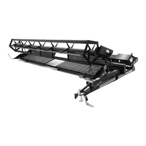
- Page 1 Model 3020 PULL-TYPE WINDROWER OPERATOR’S MANUAL Form 147021 Issue 05/05 Sugg. Retail: $15.00...
- Page 2 Inside Front Cover (blank)
-
Page 3: Introduction
INTRODUCTION Your new Pull-Type Windrower is designed to cut, and lay in windrows, a wide variety of grain and specialty crops. Windrowing allows starting the harvest earlier, protects the crop from wind damage, and gives you more flexibility in scheduling combine time. Use this manual as your first source of information about the machine. -
Page 4: Table Of Contents
TABLE OF CONTENTS PAGE INTRODUCTION........................... i SERIAL NUMBER LOCATION ......................v SAFETY Safety Alert Symbol......................... vi Signal Words........................... vi Safety Signs ..........................vii, viii General Farm Safety........................ix, x SPECIFICATIONS Windrower ............................1 Tractor Requirements ........................1 Hardware Torque Specifications ......................2 Hydraulic Fitting Torque Specifications....................3 OPERATION Your Responsibilities as an Owner/Operator ...................4 To the New Operator........................4... - Page 5 TABLE OF CONTENTS PAGE MAINTENANCE/SERVICE Service Procedures.........................36 Greasing the Windrower ......................37-41 Telescoping Hitch Pin ........................42 Left Wheel Lock Assembly......................42 Header Flotation..........................42 Hydraulics ............................ 43,44 Removal of Header Lift Cylinder .....................44 Electrical............................45 Main Drives: Belt Alignment ..........................46 Idler Pulley Shield Alignment ......................46 Belt Tension ..........................47 Removal of Main Drive Pulley .......................47 Sickle and Sickle Drive:...
- Page 6 TABLE OF CONTENTS PAGE TROUBLE SHOOTING Windrow Formation .........................68 Crop Loss at Cutterbar......................... 68,69 Crop Loss at Drapers ........................69 Transport............................69 Drives ............................69-71 Drapers ............................71 ATTACHMENTS PTO Conversion Kit ........................72 Narrow Delivery Opening Kit......................72 Hitch Plate Kit..........................72 Left Hand Divider Rod........................72 UNLOADING &...
-
Page 7: Serial Number Location
SERIAL NUMBER LOCATION Record the serial number in the space provided. Pull Type Windrower: Serial number plate (A) is located on the side of the left hand end frame. NOTE: When ordering parts and service, be sure to give your dealer the complete and proper serial number. -
Page 8: Safety
SAFETY SAFETY ALERT SYMBOL This safety alert symbol indicates important safety messages in this manual and on safety signs on the windrower. This symbol means: ATTENTION! BECOME ALERT! YOUR SAFETY IS INVOLVED! Carefully read and follow the safety message accompanying this symbol. Why is SAFETY important to you? ·... -
Page 9: Safety Signs
SAFETY SAFETY SIGNS • The safety signs reproduced here appear on the windrower at the locations listed. • Keep safety signs clean and legible at all times. • Replace safety signs that are missing or become illegible. • If original parts on which a safety sign was installed are replaced, be sure the repair part also bears the current safety sign. - Page 10 SAFETY SAFETY SIGNS (continued) Form # 147021 Issue 05/05 viii...
-
Page 11: General Farm Safety
SAFETY GENERAL SAFETY The following are general farm safety precautions that should be part of your operating procedure for all types of machinery. 1. Protect yourself. When assembling, operating and servicing machinery, wear all the protective clothing and personal safety devices that COULD be necessary for the job at hand. - Page 12 SAFETY GENERAL SAFETY (continued) 6. Wear close-fitting clothing and cover long hair. Never wear dangling items such as scarves or bracelets. 7. Keep hands, feet, clothing and hair away from moving parts. Never attempt to clear obstructions or objects from a machine while the engine is running.
-
Page 13: Specifications
SPECIFICATIONS NOTE: Specifications listed only under 25 ft. column are common to all sizes, with exceptions listed under appropriate column. 21 FT. 25 FT. 30 FT. 36 FT. DIMENSIONS Overall Width: Transport Position 10'6" (3200 mm) 10'10" (3300 mm) 11'2" (3400 mm) 12' (3660 mm) Field Position 25'4"... -
Page 14: Hardware Torque Specifications
TORQUE SPECIFICATIONS CHECKING BOLT TORQUE The tables shown below give correct torque values for various bolts and capscrews. Tighten all bolts to the torques specified in chart unless otherwise noted throughout this manual. Check tightness of bolts periodically, using bolt torque chart as a guide. Replace hardware with the same strength bolt. ENGLISH TORQUE SPECIFICATION NC Bolt Torque* Bolt... -
Page 15: Hydraulic Fitting Torque Specifications
TORQUE SPECIFICATIONS TIGHTENING HYDRAULIC O-RING FITTINGS* 1. Inspect O-ring and seat for dirt or obvious defects. Nut Size Recommended Across Turns to Tighten 2. On angle fittings, back the lock nut off until Thread Flats (after finger washer bottoms out at top of groove. Size (in.) Torque Value*... -
Page 16: Operation
OPERATION YOUR RESPONSIBILITIES AS AN OWNER/OPERATOR CAUTION: 1. It is your responsibility to read and understand this manual completely before operating the windrower. Contact your dealer if an instruction is not clear to you. 2. Follow all safety messages in the manual and on safety signs on the machine. -
Page 17: Preparing The Tractor
OPERATION PREPARING THE TRACTOR 1. Select proper tractor size: For 21', 25' or 30' units, the minimum power required is 40 hp (30 kw) and minimum tractor weight is 5000 lbs. (2270 kg). For 36' unit, the minimum power required is 50 hp (38 kw) and minimum tractor weight is 6000 lbs. - Page 18 OPERATION PREPARING THE TRACTOR (continued) 6. Tractor must be equipped with a seven terminal outlet (F) to supply power to the windrower's warning and work lights. SEVEN TERMINAL ELECTRICAL OUTLET 7. For 36' units only: Attach chain anchor plate (G) to the tractor drawbar as follows: - Position plate on drawbar so hitch pin hole lines up with 1-1/4 inch (32 mm) hole in plate at (H).
-
Page 19: Preparing The Windrower
OPERATION PREPARING THE WINDROWER 1. Be sure windrower is set up to match tractor PTO speed. A quick way to check is to measure the outside diameter of the driven pulley (A): 9-1/2 inch (240 mm) - 540 rpm 12-1/2 inch (320 mm) - 1000 rpm If not matched, and tractor PTO speed cannot be varied, order a conversion kit from your windrower dealer. - Page 20 OPERATION PREPARING THE WINDROWER (continued) 5. Check the tires and inflate if necessary. Recommended pressure is 24 to 28 psi (165 to 190 kPa). CAUTION: When inflating tires, use a clip-on chuck and extension hose long enough to allow you to stand to one side and not facing the tire.
-
Page 21: Attaching Windrower To Tractor
OPERATION ATTACHING WINDROWER TO TRACTOR CAUTION: Shut off tractor, engage parking brake and remove key before working around hitch. CAUTION: Never attach windrower to tractor rear axle or three-point hitch arms. 1. Attach windrower hitch to tractor drawbar with a 1-3/16 inch (30 mm) pin and secure with a spring locking pin or other suitable fastener. - Page 22 OPERATION ATTACHING WINDROWER TO TRACTOR (continued) 5. Connect the windrower wiring harness plug (A) to outlet on tractor. 6. Connect hydraulic hoses to tractor remote cylinder control valves. CONNECT WIRING HARNESS 7. For 36 ft. units only: Attach stabilizer chain to tractor-mounted anchor plate as follows: - Windrower must be in transport position;...
-
Page 23: Detaching Windrower From Tractor
OPERATION DETACHING WINDROWER FROM TRACTOR CAUTION: To prevent accidental movement of tractor, shut off engine, engage parking brake, and remove key. To maintain stability, always lower the reel and cutterbar completely. Block windrower wheels before detaching from tractor. Park machine on flat level surface. Move remote cylinder control valve lever back and forth to relieve stored hydraulic pressure. - Page 24 OPERATION DETACHING WINDROWER FROM TRACTOR (continued) 5. Remove hitch pin (B) and unhook chain (C) from tractor. Wrap chain around windrower hitch for storage. REMOVE HITCH PIN AND CHAIN 6. For 36 ft. units only: Disconnect stabilizer chain (D) from tractor, storing pins (E) and (F) in position.
-
Page 25: Break-In Period
OPERATION BREAK-IN PERIOD 1. After attaching windrower to tractor for the first time, operate the machine slowly for 5 minutes, watching and listening FROM THE TRACTOR SEAT for binding or interfering parts. CAUTION: Before investigating an unusual sound or attempting to correct a problem, shut off tractor, engage parking brake and remove key. -
Page 26: Pre-Starting Checks: Annual
OPERATION PRE-STARTING CHECKS Do the following at the start of each operating season: CAUTION: 1. Review the Operator's Manual to refresh your memory on safety and operating recommendations. 2. Review all safety signs and other decals on the windrower and note hazard areas. 3. -
Page 27: Pre-Starting Checks: Daily
OPERATION PRE-STARTING CHECKS Do the following each day before start-up: CAUTION: 1. Clear the area of other persons, pets etc. Keep children away from machinery. Walk around the windrower to be sure no one is under, on or close to it. 2. -
Page 28: Operate Correctly
OPERATION OPERATE CORRECTLY CAUTION: 1. Follow all safety and operational instructions given in your tractor Operator's Manual. If you do not have a tractor manual, get one from your dealer and read it thoroughly. 2. Never attempt to start the tractor engine or operate the windrower except from the tractor seat. 3. -
Page 29: Engaging The Pto
OPERATION IMPORTANT: Satisfactory function windrower in all situations requires making proper adjustments to suit various crops and conditions. Correct operation reduces crop loss and allows cutting of more acres. As well, proper adjustments and timely maintenance will increase the length of service you receive from the machine. -
Page 30: Header Lock
OPERATION HEADER LOCK WARNING: To avoid bodily injury or death from fall of raised machine, always engage header lock (A) before going under windrower for any reason. NOTE: Should the condition arise where the lock pin cannot be installed with the header fully raised, install shim washers between bracket (B) and stop (C). -
Page 31: Ground Speed
OPERATION GROUND SPEED CAUTION: Reduce speed when turning, crossing slopes, or when travelling over rough ground. Tractor ground speed should not exceed 8 mph (13 km/h). For most crop conditions a ground speed of 5 mph (8 km/h) has been found satisfactory. Choose a ground speed that allows the sickle to cut the crop smoothly and evenly, while giving the desired windrow formation. -
Page 32: Reel Speed
OPERATION REEL SPEED Reel speed affects the smoothness and evenness of the windrow. Operating the reel too fast or too slow relative to ground speed will cause bunching in the windrow. In standing crop, reel speed should be just faster than ground speed to sweep the crop across the sickle. -
Page 33: Reel Props
OPERATION REEL PROPS WARNING: To avoid injury from fall of raised reel, always engage reel props (A) before going under raised reel for any reason. Keep pivot bolt properly tightened so prop remains in stored position when not in use, yet can be engaged with hand force. -
Page 34: Reel Position - Fore And Aft
OPERATION REEL POSITION - FORE & AFT Reel fore-aft position can be adjusted to suit various crop conditions: For straight standing crop, the reel position is normally centered above the cutterbar. For crops that are down, tangled, or leaning, move reel ahead of cutterbar. -
Page 35: Draper Speed
OPERATION DRAPER SPEED Draper speed affects the orientation of stalks in the windrow. Faster draper speeds will tend to form herringbone or dovetail configurations. See "Windrow Characteristics" in this section. Draper speed is variable from 275 to 480 feet per minute (84 to 146 m/min) by shimming. -
Page 36: Delivery Opening Width
OPERATION DELIVERY OPENING WIDTH The width of the delivery opening affects the width and configuration of the windrow. The decision to widen or narrow the opening should be based on the following factors: Combine pick-up capability Weather conditions (rain, humidity, wind) Drying time available See "Windrow Characteristics"... - Page 37 OPERATION DELIVERY OPENING WIDTH (continued) The 36 ft. windrower is factory assembled with a delivery opening of 60-3/4 inches (1545 mm). To widen opening - 36 ft. unit 1. Remove screws from connector slat of left draper. 2. Remove two bolts (B) near left leg of windrower.
-
Page 38: Delivery Opening Height
OPERATION DELIVERY OPENING HEIGHT Height of the frame tube can be adjusted within a 6” (150 mm) range by repositioning the caster wheel spindle on the supports. A lower frame tube height gives a flatter draper/guard angle, while higher frame tube heights are beneficial in bulky crops. -
Page 39: Windrow Characteristics
OPERATION WINDROW CHARACTERISTICS Factors such as ground speed, reel speed, draper speed and delivery opening will all affect the resulting windrow. You will quickly become adept at adjusting these variables to achieve the desired results. NOTE: Crop condition is a major factor in forming a good windrow. While standing or uniformly leaning crops can generally be easily formed into an acceptable windrow, such is not the case when stalks are tangled or leaning in several directions. -
Page 40: Cornering
OPERATION CORNERING Because of the long turning radius of the larger windrowers (especially 36 ft.), use the cornering procedure illustrated. This procedure will prevent swath disturbance and grain loss caused by tractor and/or windrower tires. In addition, the technique should result in a corner that can be picked up by your combine without extra turning. FIELD LIGHT The field light (A) is positioned to shine on the windrow when cutting after dark. -
Page 41: Unplugging The Sickle
OPERATION UNPLUGGING THE SICKLE WARNING: Stop tractor engine and remove key before removing plugged material from sickle. A child or even a pet could engage the drive. If the sickle plugs: 1. Stop forward movement of the tractor. 2. Lift the cutterbar about 12 inches (300 mm). 3. -
Page 42: Transporting The Windrower
OPERATION TRANSPORTING THE WINDROWER CAUTION: Use correct transport procedure as detailed here: 1. Be sure all lock pins are properly installed in transport position. See "Converting From Field Position to Transport" in this section. 2. To ensure adequate braking performance and control, tow only with a vehicle weighing at least 5000 lbs. -
Page 43: Transport Width
OPERATION TRANSPORTING THE WINDROWER (continued) 10. Transport Width - Be sure transport width (X) is as narrow as possible without compromising machine stability. Recommended transport widths (X) are: 21 ft. unit - 10'6" (3.2 m) 25 ft. unit - 10'10" (3.3 m) 30 ft. -
Page 44: Converting From Field Position To Transport
OPERATION CONVERTING FROM FIELD POSITION TO TRANSPORT 1. Raise header to full height. 2. Rotate levers from field to transport positions: a. Rotate lever on hitch to transport position (A). b. Rotate lever on left wheel lock to transport HITCH LEVER - TRANSPORT POSITION position (B). -
Page 45: Converting From Transport To Field Position
OPERATION CONVERTING FROM FIELD POSITION TO TRANSPORT 5. Install lock pins (continued) c. Install pin (E) to lock right wheel in transport position. Secure with hairpin. RIGHT WHEEL LOCK - ENGAGED CONVERTING FROM TRANSPORT TO FIELD POSITION 1. Reverse windrower while steering tractor front wheels to the left to angle caster wheel inward. - Page 46 OPERATION CONVERTING FROM TRANSPORT TO FIELD POSITION 4. Place levers and pins in field position (continued): c. Remove pin (C) at header lock and store. Secure with hairpin. HEADER LOCK PIN - STORAGE POSITION d. Rotate lever on left hand wheel lock to field position (D).
-
Page 47: Storage Procedure
OPERATION STORAGE PROCEDURE Do the following at the end of each operating season: CAUTION: 1. Clean the windrower thoroughly. Never use gasoline, naphtha or any volatile material for cleaning purposes. These materials may be toxic and/or flammable. 2. Cover cutterbar and sickle guards to prevent injury from accidental contact. -
Page 48: Maintenance/Service
MAINTENANCE/SERVICE SERVICE PROCEDURES CAUTION: To avoid personal injury, before servicing windrower opening drive covers: 1. Fully lower the header and reel. If necessary to service in the raised position, always engage header lock and reel props. 2. Disengage PTO. 3. Stop engine and remove key. 4. -
Page 49: Greasing The Windrower
MAINTENANCE/SERVICE GREASING THE WINDROWER Use an SAE Multi-Purpose High Temperature Grease with Extreme Pressure (EP2) Performance and containing a maximum of 1% moly (molybdenum disulphide). For driveline slip-joints only, increased moly content 10%) recommended. IMPORTANT: Do not use this higher moly content grease on bearings, as it may cause excessive wear in high speed applications. - Page 50 MAINTENANCE/SERVICE GREASING THE WINDROWER (continued) 50 Hours: 1. Main Hitch Pivots (A) - four fittings MAIN HITCH PIVOTS 2. Wheel Casters (B) & (C) - two fittings LEFT WHEEL CASTER RIGHT WHEEL CASTER 3. Reel Support Bushings (D) 21, 25, 30 ft. - two fittings 36 ft.
- Page 51 MAINTENANCE/SERVICE GREASING THE WINDROWER (continued) 100 Hours or Annually: 1. Drive Shaft Bearings (A) - two fittings DRIVE SHAFT BEARINGS 2. Drive Shaft Wooden Support Bearing (B) 36 ft. only - one fitting DRIVE SHAFT WOODEN SUPPORT BEARING 36 ft. ONLY 3.
- Page 52 MAINTENANCE/SERVICE GREASING THE WINDROWER 100 Hours or Annually (continued): 4. Sickle Drive Pulley Bearings (D) - one fitting 5. Pitman Bearings (E) - two fittings SICKLE DRIVE PULLEY AND PITMAN BEARINGS 6. Draper Drive Shaft Bearings (F) 21, 25, 36 ft. - three fittings 30 ft.
- Page 53 MAINTENANCE/SERVICE GREASING THE WINDROWER 100 Hours or Annually (continued): 8. Draper Drive Roller Bearings (H) - two fittings DRAPER DRIVE ROLLER BEARINGS 9. Reel Drive Pulley Hub (K) - one fitting 10. Split Reel Connector Block (L) 36’ – one fitting SPLIT REEL CONNECTOR BLOCK REEL DRIVE PULLEY HUB 36’...
-
Page 54: Telescoping Hitch Pin
MAINTENANCE/SERVICE TELESCOPING HITCH PIN Lubricate pin (A) every 100 hours or once per season with a lightweight (SAE 30) oil. OIL TELESCOPING HITCH PIN LEFT WHEEL LOCK ASSEMBLY Lubricate handle (B) and lock assembly every 100 hours or once per season with a lightweight (SAE 30) oil. -
Page 55: Hydraulics
MAINTENANCE/SERVICE HYDRAULICS Check hydraulic hoses and lines daily for signs of leaks. WARNING: Avoid high-pressure fluids. Escaping fluid can penetrate the skin causing serious injury. Relieve pressure before disconnecting hydraulic lines. Tighten all connections before applying pressure. Keep hands and body away from pin- holes and nozzles which eject fluids under high pressure. -
Page 56: Removal Of Header Lift Cylinder
MAINTENANCE/SERVICE HYDRAULICS (continued): HYDRAULIC FLOW CHART - 36 ft. UNIT NOTE: Leakage at center reel lift cylinder may be caused by excess oil in system. If so, bleed excess oil through R/H cylinder bleed screw. Removal of Header lift Cylinder WARNING: Should it be necessary to remove the header lift cylinder, stored energy in the header float... -
Page 57: Electrical
MAINTENANCE/SERVICE ELECTRICAL Use electrical tape and wire clips as required to prevent wires from dragging or rubbing. Keep lights clean and replace burnt bulbs and sealed beams. To replace amber or red light bulbs: 1. Using a screwdriver, pry plastic lens (B) from fixture. -
Page 58: Main Drives
MAINTENANCE/SERVICE MAIN DRIVES Main Drive Belt Alignment IMPORTANT: Maintenance of proper belt align- ment is critical to preventing the belt from rolling over in operation, causing premature failure. For proper belt alignment, the forward edge of top idler pulley (A) must be in line with front surface of drive pulley (B). -
Page 59: Belt Tension
MAINTENANCE/SERVICE MAIN DRIVES (continued) Main Drive Belt Tension IMPORTANT: To prolong belt and drive life, do not over tighten drive belt. Operate at minimum tension required to prevent slipping and excessive vibration. Recommended tension: 20 lbs. (90 N) force at mid-span (C) produces 1 inch (25 mm) CHECKING BELT TENSION deflection. -
Page 60: Sickle And Sickle Drive
MAINTENANCE/SERVICE SICKLE AND SICKLE DRIVE WARNING: Keep hands clear of the area between guards and sickle at all times. CAUTION: Wear heavy gloves when working around or handling sickles. KEEP HANDS AWAY FROM SICKLE Sickle Lubrication Apply SAE 10 or equivalent light weight oil daily (one or two drops per section) along entire length of sickle. -
Page 61: Sickle Removal And Installation
MAINTENANCE/SERVICE SICKLE AND SICKLE DRIVE (continued) To Remove Sickle WARNING: Always stand to rear of sickle during removal to reduce risk of injury from cutting edges. Wear heavy gloves when handling sickle. 1. Clean area around sickle head. Remove bolt (A). -
Page 62: Guards
MAINTENANCE/SERVICE SICKLE AND SICKLE DRIVE (continued) Guards CAUTION: Always lower reel props before working under reel. Check daily that guards are aligned to obtain proper shear cut between sickle section and guard. Sickle sections should contact shear surface of each guard. A guard straightening tool is available from your BENDING GUARD TIPS UP Dealer Parts Department. -
Page 63: Sickle Register
MAINTENANCE/SERVICE SICKLE AND SICKLE DRIVE (continued) Sickle Register Sickle register is the position of the sickle section at the stroke limit relative to the guard point. To check: 1. Turn crank pulley (A) until sickle is at right or left stroke limit. FIND STROKE LIMIT 2. -
Page 64: Sickle Drive Belt Tension
MAINTENANCE/SERVICE SICKLE AND SICKLE DRIVE (continued) Sickle Drive Belt Tension IMPORTANT: To prolong belt and drive life, do not over-tighten belt. Operate at minimum tension required to prevent slipping and excessive vibration. To adjust: WARNING: To avoid injury or death from fall of raised header, engage header lock before going under machine. -
Page 65: Reel And Reel Drive
MAINTENANCE/SERVICE REEL AND REEL DRIVE Reel Clearance From Cutterbar The reel should be adjusted to provide 2 inches (50 mm) clearance above cutterbar with reel fully lowered. To adjust: 1. Raise reel, engage reel props (A) and lower reel onto props. ENGAGE REEL PROPS 2. -
Page 66: Centering The Reel
MAINTENANCE/SERVICE REEL AND REEL DRIVE (continued) Centering the Reel Center the reel between the end sheets by adjusting the reel support arm brace (D). To adjust: 1. Loosen two nuts (E). 2. Position brace (D) as required to center reel. 3. -
Page 67: Reel Primary Drive Belt Tension
MAINTENANCE/SERVICE REEL AND REEL DRIVE (continued) Reel Primary Belt Tension IMPORTANT: Belt tension increases as reel is raised. To avoid damaging belt or idler arm, do not over-tighten belt. Operate at minimum tension required to prevent slipping. To adjust: 1. Fully raise reel and engage reel props at each reel arm. -
Page 68: Drapers And Draper Drive
MAINTENANCE/SERVICE DRAPERS AND DRAPER DRIVE Draper Care IMPORTANT: The investment in time to be sure drapers are properly adjusted and running true will greatly increase draper life. Be sure that: 1. Draper tension is released after the day's operation. 2. Draper tension is set just high enough to prevent slipping. -
Page 69: Draper Tracking
MAINTENANCE/SERVICE DRAPERS AND DRAPER DRIVE Draper Tracking (continued) To adjust drive roller position, continue as follows: 3. Release draper tension by using hand or foot to move lever (A) over-center, toward end of header. CAUTION: Spring loaded over-center action causes handle to kick back when tension is released. -
Page 70: Draper Tension
MAINTENANCE/SERVICE DRAPERS AND DRAPER DRIVE (continued) Draper Tension Draper tension is adjusted with spring assemblies at each end of the idler roller. Tension should be adjusted just tight enough to prevent slippage. Also, by varying the front and rear spring settings with respect to each other, the draper can be adjusted to track closer to, or further from the cutterbar. -
Page 71: Replacing Drapers
MAINTENANCE/SERVICE DRAPERS AND DRAPER DRIVE (continued) Replacing Drapers When installing drapers: 1. Right and left drapers are different lengths (except for 36 ft. unit). Be sure you have them properly positioned before cutting a draper you think is too long. 2. -
Page 72: Draper Drive Belt Idler Alignment
MAINTENANCE/SERVICE DRAPERS AND DRAPER DRIVE (continued) Draper Drive Belt Idler Alignment Check periodically that idlers are properly aligned and idler arm is free to pivot. To align idlers: 1. Loosen two bolts (A). 2. Turn bracket to provide proper alignment. 3. -
Page 73: Wheels And Tires: Wheel Bolts
MAINTENANCE/SERVICE WHEELS AND TIRES Wheel Bolts Check and tighten wheel bolts after the first 10 hours of operation and every 100 hours thereafter. Whenever a wheel is removed and re-installed, check torque after one hour of operation. Maintain 80 to 90 ft.lbs. (110 to 120 N⋅m) of torque. Follow the proper bolt tightening sequence shown. -
Page 74: Wheel Alignment
MAINTENANCE/SERVICE WHEELS AND TIRES (continued) Wheel Alignment Soil conditions may make it necessary to change the alignment of the left wheel to keep the windrower trailing at approximately 90° to the line of travel. NOTE: For 36 ft. units, see "Stabilizer Spring Adjustment"... -
Page 75: Tire Inflation
MAINTENANCE/SERVICE WHEELS AND TIRES (continued) Tire Inflation Check tire pressure daily. Maintain pressures recommended in Specifications section. WARNING: Service tires safely. A tire can explode during inflation and cause serious injury or death. Never increase air pressure beyond 35 psi (241 kPa) to seat the bead on the rim. -
Page 76: Stabilizer Spring Adjustment - 36 Foot Windrower
MAINTENANCE/SERVICE STABILIZER SPRING ADJUSTMENT - 36 ft. ONLY The stabilizer spring is factory set to counteract side draft in average field conditions. In hilly or wet conditions it may be necessary to increase the stabilizer effect by shortening the spring. Where less than average stabilizer effect is required to counteract side draft, the spring may be lengthened. -
Page 77: Maintenance Schedule
MAINTENANCE/SERVICE MAINTENANCE SCHEDULE The following maintenance schedule is a listing of periodic maintenance procedures, organized by service intervals. For detailed instructions, see the specific headings in Maintenance/Service section. Service Intervals The recommended service intervals are in hours of operation. Use the hour meter on the tractor to indicate when the next service interval has been reached. - Page 78 MAINTENANCE/SERVICE MAINTENANCE SCHEDULE AT FIRST USE: See "Preparing the Windrower" and "Break-In Period" in Operation section. 10 HOURS OR DAILY 1. Grease telescoping driveline. 2. Check hydraulic hoses and lines for leaks. 3. Oil sickle (except in sandy conditions). 4. Check sickle sections, guards and hold-downs. 5.
-
Page 79: Maintenance Record
MAINTENANCE RECORD Windrower No. Serial No. See Maintenance/Service section for details of each procedure. Copy this page to continue record. ACTION: - Check - Lubricate (36’) – 36’ Units Only Hour Meter Reading: Serviced By: Maintenance Procedure BREAK-IN See “Preparing the Windrower” and “Break-In Period” in Operation section.. 10 HOURS OR DAILY Telescoping Driveline Hydraulic Hoses &... -
Page 80: Trouble Shooting
TROUBLE SHOOTING SYMPTOM PROBLEM SOLUTION REF. WINDROW FORMATION Heads in center of Ground speed too fast. Reduce ground speed. windrow, butts sticking Heads in center of Draper speed too fast. Reduce draper speed windrow. (try running R/H draper slower than L/H). Windrow too narrow. -
Page 81: Crop Loss At Drapers
TROUBLE SHOOTING SYMPTOM PROBLEM SOLUTION REF. CROP LOSS AT CUTTERBAR (cont'd) Rape or flax catches at Divider rod not installed. Install divider rod to R/H or L/H divider. push crop down to allow cutting. Excessive bouncing. Float set too light Loosen float springs. -
Page 82: Drives
TROUBLE SHOOTING SYMPTOM PROBLEM SOLUTION REF. DRIVES Sickle drive pounds Loose guards or Tighten. (continued). sections. Sickle driving hard Clean sickle. (plugging). Adjust sickle hold- downs. Replace worn parts. Sickle running too fast. Install pulleys for correct PTO speed. Ragged cut stubble. Ground speed too fast. -
Page 83: Drapers
TROUBLE SHOOTING SYMPTOM PROBLEM SOLUTION REF. DRIVES (continued) Sickle drive belt Loose belt. Tighten belt. whipping. Pulley or shaft bent. Replace damaged part. PTO speed too high. Maintain proper RPM on PTO. Install correct pulleys. Belt guides missing. Install guides. Sickle loads excessive. -
Page 84: Pto Conversion Kit
ATTACHMENTS The following attachments are available from your Dealer: PTO CONVERSION KIT – 1000 to 540 RPM LEFT HAND DIVIDER ROD WholeGoods order number: B1354 Parts order number: 29792 To convert windrower to match your tractor PTO A divider rod may be added to the left divider to speed. -
Page 85: Unloading & Assembly
UNLOADING & ASSEMBLY UNLOADING THE WINDROWER Refer to Unloading and Assembly Instructions booklet for instructions on safely unloading, handling and assembling the windrower. Form # 147021 Issue 05/05... -
Page 86: Index
INDEX PAGE PAGE Assembly............73 Left Divider Rod Attachment ......72 Attaching Windrower to Tractor......9 Levelling Cutterbar .......... 26 Attachments ............72 Light, Field............28 Light - Repair........... 45 Break-In Period ..........13 Main Drives Belt Alignment......46 Main Drives Belt Tension ........ 47 Main Drives Idler Pulley Shield Alignment .. - Page 87 INDEX PAGE Safety (continued) - Signal Words..........vi - Signs ............vii - Storage Procedure ........35 - Transporting ..........30 - Your Responsibilities........4 Serial Number Locations ........v Service Procedures .........36 Shut-Down Procedure ........29 Sickle Drive Belt Tension ........52 Sickle Drive Pitman Replacement ....49 Sickle Guards and Hold-Downs ......50 Sickle Lubrication ..........48 Sickle Register ..........51...
- Page 88 PULL TYPE WINDROWER PRE-DELIVERY CHECKLIST Windrower Model: Serial No: Perform these checks and adjustments prior to delivery to your customer. See the Operator's Manual and Assembly Instructions for adjustment details. CAUTION: Carefully follow the instructions given. Be alert for safety related messages which bring your attention to hazards and unsafe practices.
Need help?
Do you have a question about the 3020 and is the answer not in the manual?
Questions and answers