MacDon PW8 Operator's Manual
Pick-up header
Hide thumbs
Also See for PW8:
- Unloading and assembly instructions (170 pages) ,
- Operator's manual (358 pages) ,
- Unloading and assembly instructions (146 pages)

Related Manuals for MacDon PW8


Summary of Contents for MacDon PW8
- Page 1 Pick-Up Header Operator’s Manual 214657 Revision A 2019 Model Year Original Instruction The harvesting specialists.
- Page 2 PW8 Pick-Up Header Published May 2018...
- Page 3 Declaration of Conformity Figure 1. EC Declaration of Conformity 214657 Revision A...
- Page 4 Figure 2. EC Declaration of Conformity 214657 Revision A...
- Page 5 Introduction The PW8 Pick-Up Header is designed to pick up windrows and feed them into a combine. This manual contains operating and maintenance procedures for the PW8 Pick-Up Header for the following combines: Combine Model Case IH 50/60/7088, 51/61/7130, 51/61/7140, 70/8010, 71/81/9120, 72/82/9230, and 72/82/9240...
- Page 6 Keep this manual handy for frequent reference and to pass on to new Operators or Owners. The PW8 Pick-Up Header Parts Catalog also is supplied with your new header. Call your Dealer if you need assistance, information, or additional copies of the manuals.
-
Page 7: List Of Revisions
List of Revisions The following table lists the changes made from the previous version of this document: Location Summary of Change New declaration of conformity. Declaration of Conformity, page i 3.3.5 Removing Right Endshield, page 343.3.6 Added illustrations Installing Right Endshield, page 35 Added steps 3.3.4 Installing Left Endshield, page 32 John Deere T-Series added... -
Page 8: Serial Number
Serial Number The serial number plate (A) is located on the left endsheet. Record the serial number of the PW8 Combine Pick-Up Header here: ____________________________________________ Figure 4. Left Side (Rear View) 214657 Revision A... -
Page 9: Table Of Contents
TABLE OF CONTENTS Declaration of Conformity..........................i Introduction.............................. iii List of Revisions ............................v Serial Number ............................vi Chapter 1: Safety ............................ 1 1.1 Safety Alert Symbols ..........................1 1.2 Signal Words ............................2 1.3 General Safety.............................3 1.4 Maintenance Safety ..........................5 1.5 Hydraulic Safety...........................6 1.6 Safety Signs ............................7 1.6.1 Installing Safety Decals .......................7 1.7 Safety Sign Locations...........................8... - Page 10 TABLE OF CONTENTS Detaching from Case IH Combine....................45 3.10.2 John Deere 60, 70, S, and T Series ..................49 Attaching to John Deere 60, 70, S, and T Series Combine ............49 Detaching from John Deere 60, 70, S, and T Series Combine ............53 3.10.3 New Holland CR/CX Series Combine..................56 Attaching to New Holland CR/CX Series Combine ..............56 Detaching from New Holland CR/CX Combine................59...
- Page 11 TABLE OF CONTENTS Removing Header Height Control System (Right Side) ..............98 Installing Header Height Sensor Assembly (Right Side) ............. 100 4.1.3 Height Sensor Output Voltage Range – Combine Requirements ..........102 Manually Checking Voltage Range................... 102 Adjusting Header Height Sensor Voltage Range (Left Side) ............105 Adjusting Header Height Sensor Voltage Range (Right Side) .............
- Page 12 TABLE OF CONTENTS 4.1.10 New Holland Combines (CR Series – Model Year 2015 and Later) ..........153 Engaging Auto Header Height Control (New Holland CR Series) ..........153 Checking Voltage Range from Combine Cab (New Holland CR Series) ........155 Calibrating Auto Header Height Control (New Holland CR Series) ..........
- Page 13 TABLE OF CONTENTS Removing Rear Draper Belt..................... 208 Installing Rear Draper Belt ...................... 210 5.7.2 Draper Fingers and Guides ...................... 211 Replacing Draper Fingers ....................... 211 Replacing Draper Guide......................212 5.7.3 Draper Deck Roller Bearings....................213 Replacing Drive Roller Bearing on Left Side of Rear Deck ............214 Replacing Drive Roller Bearing on Right Side of Rear Deck ............
- Page 14 TABLE OF CONTENTS 6.2 Seed Saver Performance Kit......................264 6.3 Combine Completion Package Kits ....................265 6.4 Auger Dent Repair Kit........................266 6.5 Pivoting Caster Wheels Kit........................ 267 Chapter 7: Troubleshooting ......................269 Chapter 8: Reference .........................273 8.1 Torque Specifications ........................273 8.1.1 Metric Bolt Specifications ......................
-
Page 15: Chapter 1: Safety
1 Safety 1.1 Safety Alert Symbols This safety alert symbol indicates important safety messages in this manual and on safety signs on the machine. This symbol means: • ATTENTION! • BECOME ALERT! • YOUR SAFETY IS INVOLVED! Carefully read and follow the safety message accompanying this symbol. -
Page 16: Signal Words
SAFETY 1.2 Signal Words Three signal words, DANGER, WARNING, and CAUTION, are used to alert you to hazardous situations. Signal words are selected using the following guidelines: DANGER Indicates an imminently hazardous situation that, if not avoided, will result in death or serious injury. WARNING Indicates a potentially hazardous situation that, if not avoided, could result in death or serious injury. -
Page 17: General Safety
SAFETY 1.3 General Safety CAUTION The following are general farm safety precautions that should be part of your operating procedure for all types of machinery. Protect yourself. • When assembling, operating, and servicing machinery, wear all protective clothing and personal safety devices that could be necessary for job at hand. - Page 18 SAFETY • Wear close-fitting clothing and cover long hair. Never wear dangling items such as scarves or bracelets. • Keep all shields in place. NEVER alter or remove safety equipment. Make sure driveline guards can rotate independently of shaft and can telescope freely. •...
-
Page 19: Maintenance Safety
SAFETY 1.4 Maintenance Safety To ensure your safety while maintaining machine: • Review operator’s manual and all safety items before operation and/or maintenance of machine. • Place all controls in Neutral, stop the engine, set the park brake, remove the ignition key, and wait for all moving parts to stop before servicing, adjusting, and/or repairing. -
Page 20: Hydraulic Safety
SAFETY 1.5 Hydraulic Safety • Always place all hydraulic controls in Neutral before dismounting. • Make sure that all components in hydraulic system are kept clean and in good condition. • Replace any worn, cut, abraded, flattened, or crimped hoses and steel lines. •... -
Page 21: Safety Signs
• Replacement safety signs are available from your MacDon Dealer Parts Department. Figure 1.14: Operator’s Manual Decal 1.6.1 Installing Safety Decals 1. Clean and dry installation area. 2. Decide on exact location before you remove decal backing paper. -
Page 22: Safety Sign Locations
SAFETY 1.7 Safety Sign Locations Figure 1.15: Header Decals – Case IH A - MD #184370 B - MD #166466 C - MD #184372 D - MD #184422 E - MD #184420 F - MD #237298 Figure 1.16: Header Decals 214657 Revision A... - Page 23 SAFETY Figure 1.17: Header Decals – John Deere A - MD #184370 B - MD #166466 C - MD #184372 D - MD #184422 E - MD #184420 F - MD #237298 Figure 1.18: Header Decals 214657 Revision A...
- Page 24 SAFETY Figure 1.19: Header Decals – New Holland A - MD #184370 B - MD #166466 C - MD #184372 D - MD #184422 E - MD #184420 F - MD #237298 Figure 1.20: Header Decals 214657 Revision A...
- Page 25 SAFETY Figure 1.21: Header Decals – Versatile A - MD #184370 B - MD #166466 C - MD #184372 D - MD #184422 E - MD #184420 F - MD #237298 Figure 1.22: Header Decals 214657 Revision A...
- Page 26 SAFETY Figure 1.23: Driveline and Hold-Down Decals – Case IH A - MD #30316 B - MD #191099 C - MD #36651 D - MD #184422 (Behind Endshield) E - MD #237229 F - MD #237254 Figure 1.24: Driveline and Hold-Down Decals 214657 Revision A...
- Page 27 SAFETY Figure 1.25: Driveline and Hold-Down Decals – John Deere A - MD #30316 B - MD #191099 C - MD #36651 D - MD #184422 (Behind Endshield) E - MD #237229 F - MD #237254 Figure 1.26: Driveline and Hold-Down Decals 214657 Revision A...
- Page 28 SAFETY Figure 1.27: Driveline and Hold-Down Decals – New Holland A - MD #30316 B - MD #191099 C - MD #36651 D - MD #184422 (Behind Endshield) E - MD #237229 F - MD #237254 Figure 1.28: Driveline and Hold-Down Decals 214657 Revision A...
- Page 29 SAFETY Figure 1.29: Driveline and Hold-Down Decals – Versatile A - MD #30316 B - MD #191099 C - MD #36651 D - MD #184422 (Behind Endshield) E - MD #237229 F - MD #237254 Figure 1.30: Driveline and Hold-Down Decals 214657 Revision A...
-
Page 30: Understanding Safety Signs
SAFETY 1.8 Understanding Safety Signs MD #30316 Rotating driveline DANGER • Rotating driveline contact can cause death—keep away! Do NOT operate without: • All driveline guards, tractor, and equipment shields in place. • Drivelines securely attached at both ends. • Driveline guards that turn freely on driveline. Figure 1.31: MD #30316 MD #36651 Rotating driveline... - Page 31 SAFETY MD #184370 Crushing hazard CAUTION • Rest header on ground or engage cylinder safety props before going under unit. • Failure to comply could result in death or serious injury. Figure 1.34: MD #184370 MD #184371 Hand entanglement hazard WARNING •...
- Page 32 SAFETY • Disengage header drive, put transmission in Neutral, and wait for all movement to stop before leaving operator’s position. • Stop the engine and remove the key from the ignition before servicing, adjusting, lubricating, cleaning, or unplugging machine. • Engage safety props to prevent lowering of raised unit before servicing in the raised position.
- Page 33 SAFETY MD #191099 Auger entanglement hazard CAUTION • To avoid injury from entanglement with rotating auger, stand clear of header while machine is running. General hazard pertaining to machine operation and servicing CAUTION • Read the operator’s manual and follow safety instructions.
- Page 34 SAFETY MD #237254 Header entanglement hazard CAUTION • To avoid injury from entanglement with crop gathering elements, stand clear of header while machine is running. Figure 1.41: MD #237254 MD #237298 Auger entanglement hazard CAUTION • To avoid injury from rotating auger, stand clear of auger while machine is running.
-
Page 35: Chapter 2: Product Overview
2 Product Overview 2.1 Header Specifications Table 2.1 Header Specifications Components Specifications Frame and Structure Width to edge of tires Width (transport lights extended) Refer to 2.2 Header Dimensions, page 22 Depth Height (transport lights extended) Weight (not including completion packages) 1366 kg (3006 lb.) Carrier Case IH, New Holland, John Deere, Versatile... -
Page 36: Header Dimensions
PRODUCT OVERVIEW 2.2 Header Dimensions Figure 2.1: Header Dimensions A - 565.8 cm (222-3/4 in.) B - 516.9 cm (203-1/2 in.) C - 452.3 cm (178-1/8 in.) D - 476.6 cm (187-5/8 in.) E - 531.8 cm (209-3/8 in.) Figure 2.2: Header Dimensions A - 246.1 cm (96-7/8 in.) B - 251.3 cm (98-7/8 in.) C - 154.4 cm (60-3/4 in.) -
Page 37: Component Identification
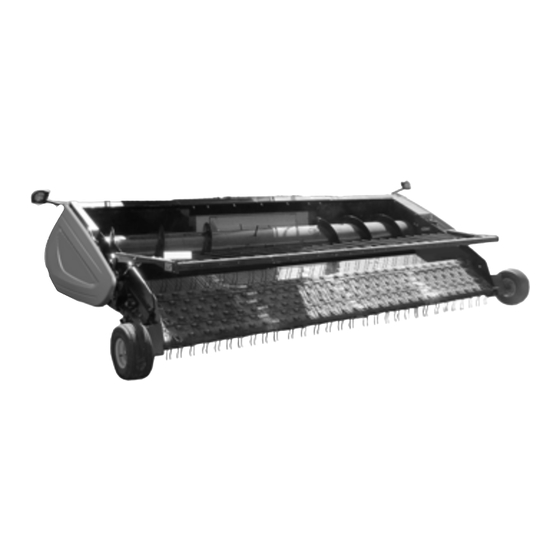
PRODUCT OVERVIEW 2.3 Component Identification Figure 2.3: PW8 Header A - Transport Light B - Endshield (Fixed) C - Transition Frame D - Stripper Plate E - Auger F - Auger Finger G - Auger Pan H - Multicoupler Receptacle... -
Page 38: Definitions
PRODUCT OVERVIEW 2.4 Definitions The following definitions and acronyms may be used in this manual: Term Definition American Petroleum Institute. ASTM American Society of Testing and Materials. Bolt A headed and externally threaded fastener that is designed to be paired with a nut. CGVW Combined Gross Vehicle Weight. - Page 39 PRODUCT OVERVIEW Term Definition A tightening procedure where the fitting is assembled to a precondition (finger tight) Torque angle and then the nut is turned further a number of degrees or a number of flats to achieve its final position. The relationship between the assembly torque applied to a piece of hardware and Torque-tension the axial load it induces in the bolt or screw.
-
Page 41: Chapter 3: Operation
3 Operation 3.1 Owner/Operator Responsibilities CAUTION • It is your responsibility to read and understand this manual completely before operating the header. Contact your Dealer if an instruction is not clear to you. • Follow all safety messages in the manual and on safety decals applied to the machine. •... -
Page 42: Operational Safety
OPERATION 3.2 Operational Safety CAUTION • Follow all safety and operational instructions given in your combine Operator's Manual. If you do not have a combine manual, get one from your Dealer and read it thoroughly. • Never start or move the machine until you are sure all bystanders have cleared the area. •... -
Page 43: Endshields
OPERATION 3.3 Endshields The endshields are molded polyethylene covers that are attached to the ends of the header. They provide shielding for the header drive components and also display the make of the combine. The left endshield is hinged to the endsheet and can be opened for routine maintenance or easily removed for major servicing. -
Page 44: Closing Left Endshield
OPERATION 3.3.2 Closing Left Endshield 1. Move endshield (A) slightly so support (B) can be moved out of the locked position. Figure 3.3: Endshield Support 2. Close endshield (A) ensuring magnet (B) and stop (C) in header frame are aligned. This will ensure that latch (D) aligns with receptacle (E). -
Page 45: Removing Left Endshield
OPERATION 4. Close endshield (D) and use a slotted screwdriver to turn latch (A) clockwise until it stops (slightly more than one-half turn). NOTE: When latch is fully engaged, the slot will align with notch (C), and the endshield will draw tightly against the header. -
Page 46: Installing Left Endshield
OPERATION 3. Swing endshield (A) fully back and loosen nuts (B) on clips (C) at back of endshield so clips disengage slots in header frame. 4. Move endshield (A) away from header. Figure 3.8: Removing Endshield 3.3.4 Installing Left Endshield 1. - Page 47 OPERATION 5. Open the endshield (C) slightly so the support (B) can be installed onto endshield. Check that washer (D) is between the support and the endshield. 6. Install nut (A), leaving a gap of 8–10 mm (5/16–3/8 in.) between the nut and washer (D), which allows support (B) to move.
-
Page 48: Removing Right Endshield
OPERATION 3.3.5 Removing Right Endshield DANGER To avoid bodily injury or death from unexpected startup of machine, always stop engine and remove key from ignition before leaving operator’s seat for any reason. 1. Lower header to ground, shut down engine, and remove key from ignition. -
Page 49: Installing Right Endshield
OPERATION 3.3.6 Installing Right Endshield DANGER To avoid bodily injury or death from unexpected startup of machine, always stop engine and remove key from ignition before leaving operator’s seat for any reason. 1. Lower header to ground, shut down engine, and remove key from ignition. -
Page 50: Header Lift Cylinder Safety Props
OPERATION 3.4 Header Lift Cylinder Safety Props Refer to your combine operator’s manual. IMPORTANT: Always engage combine safety props before working on header in elevated position. 214657 Revision A... -
Page 51: Engaging Hold-Down Lift Cylinder Safety Props
OPERATION 3.5 Engaging Hold-Down Lift Cylinder Safety Props DANGER To avoid bodily injury or death from unexpected start-up or fall of a raised machine, always stop engine and remove key before leaving the operator’s seat, and always engage safety props before going under the machine for any reason. -
Page 52: Daily Start-Up Check
OPERATION 3.6 Daily Start-Up Check CAUTION • Ensure combine and header are properly attached, all controls are in neutral and combine brake is engaged. • Clear the area of other persons, pets, etc. Keep children away from machinery. Walk around the machine to make sure no one is under, on, or close to it. -
Page 53: Shutting Down The Machine
OPERATION 3.7 Shutting down the Machine DANGER To avoid bodily injury or death from unexpected start-up or fall of a raised machine, always stop engine and remove key before leaving the operator’s seat, and always engage safety props before going under the machine for any reason. -
Page 54: Break-In Period
OPERATION 3.8 Break-In Period CAUTION Before investigating an unusual sound or attempting to correct a problem, shut off engine, engage parking brake, and remove key. 1. After attaching header to combine for the first time, operate the machine at low speed for five minutes while carefully watching and listening from the operator’s seat for binding or interfering parts. -
Page 55: Changing Header Opening
OPERATION 3.9 Changing Header Opening To minimize setup at the dealership, PW8 Pick-Up Headers are factory-configured to suit a particular combine make, model, and feeder house size. Each header configuration includes the parts and hardware needed to fit a different combine model within the same brand family. Refer to the following chart: NOTE: The conversion procedure is included in the Unloading and Assembly Instruction provided with the header. -
Page 56: Header Attachment And Detachment
OPERATION 3.10 Header Attachment and Detachment This section provides instructions for attaching/detaching the PW8 Pick-Up Header to/from the combines listed in Table 3.2, page Table 3.2 Attaching PW8 Header to Combine Combine Refer to Case IH 3.10.1 Case IH, page 42 John Deere 60, 70, and S Series 3.10.2 John Deere 60, 70, S, and T Series, page 49... - Page 57 OPERATION 2. Drive combine slowly up to header until feeder house saddle (A) is directly under the header top beam (B). 3. Raise feeder house slightly to lift header ensuring feeder house saddle (A) is properly engaged in header frame. 4.
- Page 58 OPERATION 9. Rotate disc (B) on header driveline storage hook (A) and remove driveline from hook. Figure 3.24: Driveline in Storage Position 10. Pull back collar (A) on end of driveline and push onto combine output shaft (B) until collar locks. Figure 3.25: Attaching Driveline 11.
-
Page 59: Detaching From Case Ih Combine
OPERATION 14. Position coupler (A) onto header receptacle and push handle (B) downward to engage coupler pins in receptacle. 15. Push handle to closed position until lock button (C) snaps out. 16. Open cover (D) on header electrical receptacle. 17. Remove electrical connector (E) from storage cup on combine. - Page 60 OPERATION 4. Position coupler (A) onto storage plate (B) on combine. Figure 3.29: Coupler Storage Location 5. Disconnect electrical connector (A) from header. Figure 3.30: Electrical Connector 6. Place electrical connector (A) into storage cup (B) on combine. Figure 3.31: Electrical Connector Storage 214657 Revision A...
- Page 61 OPERATION 7. Close cover on header electrical receptacle (A). 8. Push handle (B) on header down into storage position until lock button (C) snaps out. 9. Close cover (D). Figure 3.32: Locking Multicoupler 10. Open driveshield (A) on combine. 11. Pull back collar (B) on driveline (C), and remove driveline from combine.
- Page 62 OPERATION 12. Slide driveline into storage hook (A) on header and rotate disc (B) to secure driveline. Figure 3.34: Driveline in Storage Position 13. Close driveshield (A) on combine. Figure 3.35: Driveshield 14. Lift lever (A) and pull and lower handle (B) to disengage feeder house/header lock (C).
-
Page 63: John Deere 60, 70, S, And T Series
OPERATION 3.10.2 John Deere 60, 70, S, and T Series This section provides instructions for attaching/detaching the PW8 Pick-Up Header to/from John Deere 96/97/9860STS, 96/97/9870, S650/660/670/680/690, 9660WTS, and T670 combines. Attaching to John Deere 60, 70, S, and T Series Combine... - Page 64 OPERATION 5. Open driveshield (A) on combine feeder house. Figure 3.39: Combine Driveshield 6. Rotate disc (B) on header driveline storage hook (A) and remove driveline from hook. Figure 3.40: Driveline in Storage Position 7. Pull back collar (A) on end of driveline and slide driveline on feeder house driveshaft until the collar locks.
- Page 65 OPERATION 9. Remove cover (A) from combine multicoupler receptacle. Figure 3.42: Combine Receptacle 10. Pull handle (A) on header to release multicoupler (B) from storage position, remove coupler, and push handle back into header to store. Figure 3.43: Releasing Coupler 11.
- Page 66 OPERATION 13. Pull handle (A) from vertical to fully horizontal position to fully engage multicoupler and to extend pins (B) at base of feeder house into the locking plates (C). Knob (D) will engage lock handle. Figure 3.45: Locking Feeder House NOTE: If handle does not move to fully horizontal position, check alignment of locking plates (A) on the header with...
-
Page 67: Detaching From John Deere 60, 70, S, And T Series Combine
OPERATION Detaching from John Deere 60, 70, S, and T Series Combine DANGER To avoid bodily injury or death from unexpected startup of machine, always stop engine and remove key from ignition before leaving operator’s seat for any reason. 1. Choose a level area, and position the header slightly off the ground. 2. - Page 68 OPERATION 5. Raise handle (A) to lock coupler. 6. Open feeder house driveshield (B). Figure 3.49: Locking Coupler 7. Pull back collar (A) on driveline, and remove driveline from combine output shaft. Figure 3.50: Detaching Driveline 8. Slide driveline into storage hook (A) on header and rotate disc (B) to secure driveline.
- Page 69 OPERATION 9. Close combine driveshield (A). 10. Lower feeder house until saddle (B) disengages and clears header top beam (C). 11. Slowly back combine away from header. Figure 3.52: Disengaging Header 214657 Revision A...
-
Page 70: New Holland Cr/Cx Series Combine
OPERATION 3.10.3 New Holland CR/CX Series Combine This section provides instructions for attaching/detaching the PW8 Pick-Up Header to/from all New Holland CR/CX Series combines. Attaching to New Holland CR/CX Series Combine DANGER To avoid bodily injury or death from unexpected startup of machine, always stop engine and remove key from ignition before leaving operator’s seat for any reason. - Page 71 OPERATION 4. Lift lever (A) on header at left side of feeder house and push handle (B) on combine so that hooks (C) engage pins (D) on both sides of the feeder house. 5. Push down on lever (A) so that slot in lever engages handle (B) to lock handle in place.
- Page 72 OPERATION 9. Pull back collar (B) on end of driveline and push onto combine output shaft (A) until collar locks. Figure 3.57: Attaching Driveline 10. Open cover (A). 11. Push in lock button (B) and pull handle (C) halfway up to open position.
-
Page 73: Detaching From New Holland Cr/Cx Combine
OPERATION 13. Position coupler onto header receptacle (A) and push handle (B) downward to engage pins into receptacle. 14. Push handle (B) to closed position until lock button (C) snaps out. 15. Open cover (D) on header electrical receptacle. 16. Remove electrical connector (E) from combine. 17. - Page 74 OPERATION 5. Position coupler (A) onto storage plate (B) on combine. 6. Disconnect electrical connector from header, and place in storage cup (C) on combine. Figure 3.62: Coupler and Electrical Connector Storage Location 7. Close cover (A) on header hydraulic receptacle, and cover (B) on electrical receptacle.
-
Page 75: Versatile
13. Slowly back combine away from header. Figure 3.66: Disengaging Header 3.10.4 Versatile This section provides instructions for attaching/detaching the PW8 Pick-Up Header to/from Versatile RT490 combines. Attaching to Versatile Combine DANGER To avoid bodily injury or death from unexpected startup of machine, always stop engine and remove key from ignition before leaving operator’s seat for any reason. - Page 76 OPERATION 1. Check that pins (A) at lower corners of header opening are retracted. Figure 3.67: Locking Pins Retracted 2. Drive combine slowly up to header until feeder house posts (A) are directly under the header top brackets (B). 3. Raise feeder house to lift header, ensuring posts (A) are properly engaged around the header frame (B).
- Page 77 OPERATION 9. Loosen the seven bolts (A) along the top beam (B) on the auger side of the header. Figure 3.70: Top Beam (Front View) 10. Loosen the seven bolts (A) along the top beam (B) on the back side of the header. Figure 3.71: Top Beam (Rear View) 11.
- Page 78 OPERATION 14. Rotate disc (B) on the header driveline storage hook (A), and remove driveline from the hook. Figure 3.73: Driveline in Storage Position 15. Pull back collar (A) at the end of driveline and push onto the combine output shaft (B) until collar locks. Figure 3.74: Driveline 16.
-
Page 79: Detaching From Versatile Combine
OPERATION 18. Remove coupler (A) from combine and clean mating surfaces. Figure 3.76: Versatile Coupler 19. Position coupler (A) onto header receptacle and push handle (B) downward to engage coupler pins into receptacle. 20. Push handle to closed position until lock button (C) snaps out. - Page 80 OPERATION 3. Push in lock button (C), and pull handle (B) upward to release coupler (A). 4. Remove coupler (A) from header receptacle. Figure 3.78: Releasing Coupler 5. Position coupler (A) onto storage plate (B) on combine. 6. Disconnect electrical connector from header, and place in storage cup (C) on combine.
- Page 81 OPERATION 9. Pull back collar on driveline (A) and remove driveline from combine. Figure 3.81: Detaching Driveline 10. Slide driveline into storage hook (A) on header and rotate disc (B) to secure driveline. Figure 3.82: Driveline 11. Rotate pin stop (C) from lowered position (see inset), and disengage pin (B) from feeder house using handle (A).
- Page 82 OPERATION 12. Start combine and lower header to ground until feeder house posts (A) disengage from header. 13. Slowly back combine away from header. Figure 3.84: Disengaging Header 214657 Revision A...
-
Page 83: Header Transport
OPERATION 3.11 Header Transport Refer to your combine operator’s manual for transporting headers when attached to the combine. 3.11.1 Transport Lights The transport lights (A), which are mounted on both ends of the header, are activated by switches inside the combine cab. -
Page 84: Header Operation
OPERATION 3.12 Header Operation Satisfactory operation of the header in all situations requires making proper adjustments to suit various crops and conditions. Proper operation reduces crop loss and increases productivity, and proper adjustments and timely maintenance will increase the length of service you receive from your machine. The variables listed in Table 3.3, page 70 and detailed on the following pages will affect header performance. -
Page 85: Adjusting Draper Speed
OPERATION The following operating speed is suggested: Front and Rear Deck Aft Roller: 51 rpm per 1.6 km/h (1 mph) of combine ground speed. Example: For combining at 8 km/h (5 mph), the rear roller shaft should run at 51 x (8/1.6) = 255 rpm (51 x 5 mph = 255 rpm). -
Page 86: Auger Operation
OPERATION 3.12.2 Auger Operation Auger Speed The header is equipped with an auger drive sprocket to match the combine. The auger is chain-driven by a direct connection to the feeder house, and auger speed depends on the feeder house speed. You can adjust auger speeds from the combine to suit crop conditions. -
Page 87: Adjusting Auger Position
OPERATION Adjusting Auger Position The auger is adjustable on both ends in order to maintain uniform clearance across the entire width of the header. DANGER To avoid bodily injury or death from unexpected startup of machine, always stop engine and remove key from ignition before leaving operator’s seat for any reason. -
Page 88: Auger Float
OPERATION Figure 3.91: Right Side Auger Stop Auger Float The auger has an upward float range of 74 mm (3 in.), but it can be locked to operate in rigid-header mode. Locking Auger Float DANGER To avoid bodily injury or death from unexpected startup of machine, always stop engine and remove key from ignition before leaving operator’s seat for any reason. - Page 89 OPERATION 3. Loosen two bolts (A) on auger upstops (B) at the left side of header. 4. Slide the stops (B) downwards until they contact the rubber blocks (C) on the auger arm. 5. Tighten bolts (A). Figure 3.93: Left Stop 6.
- Page 90 OPERATION Unlocking Auger Float DANGER To avoid bodily injury or death from unexpected startup of machine, always stop engine and remove key from ignition before leaving operator’s seat for any reason. 1. Lower the header to the ground, shut down the combine, and remove the key from the ignition. 2.
-
Page 91: Stripper Plate Clearance
OPERATION 6. Loosen the two bolts (A) on auger upstops (B) at the right side of header. 7. Slide stops (C) upwards to desired float range. 8. Tighten bolts (A). Figure 3.98: Right Stop 9. Close the left endshield (A). Refer to 3.3.2 Closing Left Endshield, page Figure 3.99: Left Endshield... - Page 92 OPERATION Checking Stripper Plate Clearance Check the stripper plate clearance whenever the auger position is changed, and adjust if necessary. DANGER To avoid bodily injury or death from unexpected startup of machine, always stop engine and remove key from ignition before leaving operator’s seat for any reason. 1.
-
Page 93: Operating Height
OPERATION 3.12.3 Operating Height Header Height Header height is the distance between the deck pivot and the ground. Recommended operating height (A) is between 4 and 5 on the end plate decal or 305 mm (12 in.) above the ground. Figure 3.103: Operating Height Header height adjustments are made using the combine header height control. -
Page 94: Pick-Up Height
OPERATION Pick-Up Height Pick-up height (A) is the distance between the pick-up finger and the ground. The recommended pick-up height is 25 mm (1 in.), but it may need to be adjusted to suit field conditions. The following symptoms indicate that an adjustment is necessary: •... - Page 95 OPERATION 3. Check the pick-up height (A). Refer to Pick-Up Height, page 80, and complete Steps 4, page 81 10, page 81, if adjustment is necessary. Figure 3.107: Pick-Up Height 4. Use the combine controls to fully raise the header and take the load off the wheels.
-
Page 96: Adjusting Header Float
OPERATION 3.12.4 Adjusting Header Float Header float is factory set, but it can be adjusted if the wheel ground pressure is higher than desired or if it is too light and the wheels don’t follow ground terrain. DANGER To avoid bodily injury or death from unexpected startup of machine, always stop engine and remove key from ignition before leaving operator’s seat for any reason. - Page 97 OPERATION 5. Check that all spring tension is released from the spring float assembly (A). Remove cotter pin (B), clevis pin (C), and three flat washers (D). NOTE: When spring tension is fully released, spring coils should be fully collapsed and the spring float assembly should rock from side to side when moved by hand.
-
Page 98: Hold-Downs
OPERATION 3.12.5 Hold-Downs Hold-downs help crop to transition smoothly from the drapers to the auger and can be adjusted for crop conditions. Hold-Down Position Hold-down position refers to the position of the fiberglass rods (A) with respect to the swath and can be adjusted according to crop conditions. -
Page 99: Adjusting Hold-Down Rod Angle
OPERATION Adjusting Hold-Down Rod Angle The angle between the fiberglass rods (C) and the hold-down support arms is factory-set to optimize crop flow into the combine. The factory setting should be satisfactory for most crop conditions, but the rods are adjustable if necessary. -
Page 100: Installing Crop Deflectors
OPERATION 3. Remove two M12 x 25 bolts (B) and nuts and remove crop deflector (A). 4. Repeat for opposite side. 5. Store deflectors and hardware in combine cab or an alternative safe location. Figure 3.115: Crop Deflector Installing Crop Deflectors 1. -
Page 101: Draper Belt Tension
OPERATION 3.12.7 Draper Belt Tension The pick-up draper belt tension is set at the factory but should be checked before operating. NOTE: • There should be visible sag in the underside of the draper. • Draper tension needs to be set only to prevent slippage. •... -
Page 102: Adjusting Front Draper Belt Tension
OPERATION Adjusting Front Draper Belt Tension Draper belt tension is factory-set, but it should be checked before operating. Figure 3.118: Front Deck Adjusting Bolts The stepped position indicator gauges are used to precisely align each side of the front and rear decks. Each notch (A) represents an adjustment of 1 mm (3/64 in.). - Page 103 OPERATION 5. Loosen jam nut (A) on the right side of the header, and turn adjuster nut (B) until the position of stepped position indicator gauge (C) is identical to the left side. Figure 3.121: Right Side Stepped Position Indicator Gauge 6.
-
Page 104: Adjusting Rear Draper Belt Tension
OPERATION Adjusting Rear Draper Belt Tension The stepped position indicator gauges are used to precisely align each side of the front and rear decks. Each notch (A) represents an adjustment of 1 mm (3/64 in.). Figure 3.123: Stepped Position Indicators 1. -
Page 105: Driveline
OPERATION 3.12.8 Driveline Clutch The header-to-combine driveline contains a radial pin clutch (A) that provides protection against overload. When the auger encounters an obstruction, an overload occurs and the clutch slips while making a rattling sound and pulsating action. Frequent slippage of more than 2 or 3 seconds may result in clutch damage. -
Page 106: Unplugging The Header
OPERATION 3.13 Unplugging the Header DANGER To avoid bodily injury or death from unexpected startup of machine, always stop engine and remove key from ignition before leaving operator’s seat for any reason. 1. Stop forward movement of the combine and disengage the header. 2. -
Page 107: Adjusting The Pan Seal Assembly
OPERATION 3.14 Adjusting the Pan Seal Assembly The flap provides a tighter seal to the rear draper, but the draper connection hardware will eventually wear down the rubber flap. If plugging occurs between the rear draper and the pan seal bar, the rubber flap can be removed to eliminate the pan seal. -
Page 108: Storing The Header
OPERATION 3.15 Storing the Header Perform the following tasks before storing the header at the end of each operating season: CAUTION Never use gasoline, naphtha, or any volatile material for cleaning purposes. These materials may be toxic and/or flammable. 1. Clean the header thoroughly. 2. -
Page 109: Chapter 4: Ahhc System
NOTE: This section does not apply to Versatile combines. Sensors installed at each end of the PW8 Pick-Up Header send a signal to the combine allowing it to maintain a consistent cutting height as the header follows ground contours. PW8 Pick-Up Headers are factory-equipped for AHHC; however, before using AHHC feature, you must do the following: 1. -
Page 110: Ahhc Sensor Operation
4.1.2 Header Height Sensors The PW8 Pick-Up Header is equipped with two height sensors—one at each end of header. The height sensors do not require maintenance, but they may need to be repaired or replaced due to normal wear and tear. -
Page 111: Removing Header Height Sensor Assembly (Left Side)
AHHC SYSTEM Removing Header Height Sensor Assembly (Left Side) DANGER To avoid bodily injury or death from unexpected startup of machine, always stop engine and remove key from ignition before leaving operator’s seat for any reason. 1. Lower header to ground, shut down combine, and remove key from ignition. 2. -
Page 112: Installing Header Height Sensor Assembly (Left Side)
AHHC SYSTEM Installing Header Height Sensor Assembly (Left Side) 1. Install control arm (C). Ensure that flat side is facing towards header. 2. Install sensor (B), center bolts in slots, and secure with nuts (A). Figure 4.5: Header Height Sensor Assembly – Left Side 3. - Page 113 AHHC SYSTEM 3. Locate access panel on inside of right end frame. Remove two bolts (A) from access panel (B). 4. Remove access panel (B). Figure 4.7: Header Height System Access Panel – Right Side 5. Disconnect wire harness (A). 6.
-
Page 114: Installing Header Height Sensor Assembly (Right Side)
AHHC SYSTEM 9. Locate plug (A) on outboard side of endsheet and remove plug to gain access to nut (B) securing long control arm to frame. 10. Remove nut (B). Figure 4.10: Right Endsheet 11. Remove long control arm (A) complete with linkage rod, rod end clip, and activator arm. - Page 115 AHHC SYSTEM 2. Install nut (B). 3. Install hole plug (A). Figure 4.13: Right Endsheet 4. Install control arm (C). Ensure that flat side is facing towards header. 5. Install sensor (B), center bolts in slots, and secure with nuts (A). Figure 4.14: Header Height Sensor Assembly –...
-
Page 116: Height Sensor Output Voltage Range - Combine Requirements
AHHC SYSTEM 8. Install access panel (B), and secure it with bolts (A). NOTE: Auger has been removed for illustration purposes. Figure 4.16: Access Panel 4.1.3 Height Sensor Output Voltage Range – Combine Requirements The height sensor output must be within a specific voltage range for each combine or the auto header height control (AHHC) feature will not work properly. - Page 117 AHHC SYSTEM 4. Locate left height sensor (A). NOTE: Sensor and connector may not be exactly as shown. 5. With connector plugged into sensor, measure voltage between orange signal wire (B) in middle position on connector, and the brown ground wire (C) at one side of connector.
- Page 118 AHHC SYSTEM 7. Remove two bolts (A) from access panel (B). 8. Remove access panel (B). Figure 4.19: Right Access Panel 9. Locate right height sensor (A). NOTE: Sensor may not be exactly as shown, and view of harness is from inboard side of endsheet. 10.
-
Page 119: Adjusting Header Height Sensor Voltage Range (Left Side)
AHHC SYSTEM Adjusting Header Height Sensor Voltage Range (Left Side) DANGER To avoid bodily injury or death from unexpected startup of machine, always stop engine and remove key from ignition before leaving operator’s seat for any reason. 1. Lower header to ground, shut down combine, and remove key from ignition. 2. - Page 120 AHHC SYSTEM 4. Remove two bolts (A) from access panel (B). 5. Remove access panel (B). Figure 4.23: Right Access Panel 6. Loosen nuts (A). 7. Rotate sensor (B) until desired voltage range is achieved. Refer to 4.1.3 Height Sensor Output Voltage Range –...
-
Page 121: Case Ih 5130/6130/7130 And 5140/6140/7140 Midrange Combines
AHHC SYSTEM 4.1.4 Case IH 5130/6130/7130 and 5140/6140/7140 Midrange Combines Setting up the Header on the Combine Display (Case IH 5130/6130/7130; 5140/6140/7140) 1. On the main page of the combine display, select TOOLBOX (A). Figure 4.26: Case IH Combine Display 2. -
Page 122: Checking Voltage Range From Combine Cab
AHHC SYSTEM 6. From the BELT DRIVE TYPE menu (A), select • 1 - for most pickup headers • 2 - for 4.9 m (16 ft.) Rake-Up pickup headers • 3 - for SwathMaster pickup headers NOTE: Proper belt drive selection optimizes auto-belt to ground speed. - Page 123 AHHC SYSTEM 3. Select SETTINGS (A). The SETTINGS page opens. 4. From the GROUP menu (B), select HEADER. Figure 4.31: Case IH Combine Display 5. From the PARAMETER menu, select LEFT HEIGHT/ TILT SENSOR (A). Figure 4.32: Case IH Combine Display 6.
-
Page 124: Calibrating Auto Header Height Control (Case Ih 5130/6130/7130, 5140/6140/7140)
AHHC SYSTEM Calibrating Auto Header Height Control (Case IH 5130/6130/7130, 5140/6140/7140) NOTE: This procedure applies to combines with a software version below 28.00. For instructions on calibrating the AHHC for combines with software version 28.00 or above, refer to Calibrating Auto Header Height Control (Case Combines with Version 28.00 or Higher Software), page 118. - Page 125 AHHC SYSTEM 4. Manually raise or lower header to a second desired cutting height. 5. Press 2 on button (A). A yellow light next to the button will illuminate. Figure 4.36: Case Combine Console Up and down arrows should now appear in the MANUAL HEIGHT box (A) on the RUN 1 page on the combine display.
- Page 126 AHHC SYSTEM 7. The maximum working height can be adjusted on the HEADER SETUP page on the combine display. Enter the desired height in the MAXIMUM WORKING HEIGHT field (A). Figure 4.39: Case Combine Display – Header Setup Page 8. If you need to change the position of the one of the presets, you can fine tune this setting with button (A) on the combine console.
-
Page 127: Case Ih 7010/8010, 7120/8120/9120, 7230/8230/9230, And 7240/8240/9240 Combines
AHHC SYSTEM 4.1.5 Case IH 7010/8010, 7120/8120/9120, 7230/8230/9230, and 7240/8240/9240 Combines Checking Voltage Range from Combine Cab (Case 8010) NOTE: Changes may have been made to combine controls or display since this document was published. Refer to combine operator’s manual for updates. CAUTION Check to be sure all bystanders have cleared the area. - Page 128 AHHC SYSTEM 4. Select HDR HEIGHT/TILT (A). The SENSOR page displays. Figure 4.43: Case 8010 Combine Display 5. Select LEFT SEN (A). The exact voltage is displayed. Raise and lower header to see full range of voltage readings. Figure 4.44: Case 8010 Combine Display 6.
-
Page 129: Checking Voltage Range From Combine Cab
AHHC SYSTEM Checking Voltage Range from Combine Cab (Case IH 7010/8010; 7120/8120/9120; 7230/8230/9230; 7240/8240/9240) NOTE: Changes may have been made to combine controls or display since this document was published. Refer to combine operator’s manual for updates. CAUTION Check to be sure all bystanders have cleared the area. 1. -
Page 130: Calibrating Auto Header Height Control
AHHC SYSTEM 5. Select HEADER HEIGHT/TILT (A). The PARAMETER page opens. Figure 4.48: Case IH Combine Display 6. Select LEFT HEADER HEIGHT SEN (A), and then select GRAPH button (B). The exact voltage is displayed at top of page. Raise and lower header to see full range of voltage readings. - Page 131 AHHC SYSTEM 3. Set appropriate HEADER STYLE. Figure 4.50: Case IH Combine Display 4. Set AUTO REEL SPEED SLOPE. 5. Set HEADER PRESSURE FLOAT to NO if equipped, and ensure REEL DRIVE is HYDRAULIC. Figure 4.51: Case IH Combine Display 6.
-
Page 132: Software)
AHHC SYSTEM 8. Install FORE-AFT CONTROL and HDR FORE-AFT TILT (if applicable). Figure 4.53: Case IH Combine Display 9. Press HEAD2 at bottom of page. 10. Ensure HEADER TYPE is PICK-UP. NOTE: If recognition resistor is plugged in to header harness, you will not be able to change this. - Page 133 AHHC SYSTEM 4. Locate HEADER SENSORS and HEADER PRESSURE FLOAT fields. They will be located on either HEAD 1 or HEAD 2 tab. 5. Select ENABLE (A) in HEADER SENSORS field. 6. Select NO (B) in HEADER PRESSURE FLOAT field. Figure 4.56: Case IH Combine Display 7.
-
Page 134: Setting Preset Cutting Height
AHHC SYSTEM 11. Follow calibration steps in the order they appear in dialog box. As you proceed through calibration process, display will automatically update to show next step. NOTE: The calibration procedure will stop if the system sits idle for more than 3 minutes, or if the ESC key is pressed during any step. - Page 135 AHHC SYSTEM 6. To swap between set points, press HEADER RESUME (A). 7. To pick up header at headlands, press HEADER RESUME (A) twice. To lower, press HEADER RESUME (A). NOTE: You can fine adjust these set points by using FINE ADJUST switch (E) in figure 4.60, page 120.
-
Page 136: John Deere 60 Series Combines
AHHC SYSTEM 4.1.6 John Deere 60 Series Combines Checking Voltage Range from Combine Cab (John Deere 60 Series) The auto header height sensor output must be within a specific range, or feature will not work properly. Combine Low Voltage Limit High Voltage Limit Minimum Range John Deere 60 Series... -
Page 137: Calibrating Auto Header Height Control (John Deere 60 Series)
AHHC SYSTEM NOTE: You may need to hold HEADER DOWN switch for a few seconds to ensure feeder house is entirely down. 7. Check sensor reading on monitor. 8. Raise header so it is just off ground and check sensor reading again. 4.1.3 Height Sensor Output Voltage Range –... - Page 138 AHHC SYSTEM 4. Press UP or DOWN buttons until HDR appears on monitor. 5. Press ENTER button. HDR H-DN appears on monitor. 6. Fully lower feeder house to ground. NOTE: You may need to hold HEADER DOWN switch for a few seconds to ensure feeder house is fully lowered.
-
Page 139: Turning Off Accumulator (John Deere 60 Series)
AHHC SYSTEM Turning Off Accumulator (John Deere 60 Series) NOTE: Changes may have been made to combine controls or display since this document was published. Refer to combine operator’s manual for updates. 1. Press DIAGNOSTIC button (A) on monitor. DIA appears on the monitor. -
Page 140: Setting Sensing Grain Header Height To 50 (John Deere 60 Series)
NOTE: Do NOT use active header float function (A) in combination with MacDon auto header height control (AHHC)—the two systems will counteract one another. The header symbol (B) on display should NOT have a wavy line under it and should appear exactly as shown on Active Header Control Display in Figure 4.68, page... -
Page 141: Setting Sensitivity Of Auto Header Height Control (John Deere 60 Series)
AHHC SYSTEM Setting Sensitivity of Auto Header Height Control (John Deere 60 Series) This is also known as dead band adjustment. NOTE: Changes may have been made to combine controls or display since this document was published. Refer to combine operator’s manual for updates. 1. -
Page 142: John Deere 70 Series Combines
AHHC SYSTEM 1. Press DIAGNOSTIC button (A) on monitor. DIA appears on the monitor. 2. Press UP button (B) until EO1 appears on monitor and press ENTER (C). This is header adjustment. 3. Press UP (B) or DOWN button (E) until 114 is displayed on top portion of monitor. -
Page 143: Calibrating Feeder House Speed (John Deere 70 Series)
AHHC SYSTEM Calibrating Feeder House Speed (John Deere 70 Series) The feeder house speed must be calibrated before you calibrate auto header height control (AHHC) system. Refer to combine operator’s manual for instructions. 214657 Revision A... -
Page 144: Calibrating Auto Header Height Control (John Deere 70 Series)
AHHC SYSTEM Calibrating Auto Header Height Control (John Deere 70 Series) NOTE: Changes may have been made to combine controls or display since this document was published. Refer to combine operator’s manual for updates. CAUTION Check to be sure all bystanders have cleared the area. 1. - Page 145 AHHC SYSTEM Figure 4.73: John Deere Combine Control Console A - Scroll Knob B - Check Mark Button 214657 Revision A...
-
Page 146: Setting Sensitivity Of Auto Header Height Control (John Deere 70 Series)
AHHC SYSTEM 6. Follow steps listed on combine display to perform the calibration. NOTE: If an error code appears on page, sensor is not in correct working range. Refer to Checking Voltage Range from Combine Cab (John Deere 70 Series), page 128 to check and adjust range. - Page 147 AHHC SYSTEM 214657 Revision A...
-
Page 148: Adjusting Manual Header Raise/Lower Rate (John Deere 70 Series)
AHHC SYSTEM Adjusting Manual Header Raise/Lower Rate (John Deere 70 Series) NOTE: Changes may have been made to combine controls or display since this document was published. Refer to combine operator’s manual for updates. 1. Press button (A) and current raise/lower rate setting will appear on monitor (the lower reading, slower rate). -
Page 149: John Deere S And T Series Combines
AHHC SYSTEM 4.1.8 John Deere S and T Series Combines Checking Voltage Range from Combine Cab (John Deere S and T Series) The auto header height sensor output must be within a specific range, or feature will not work properly. Combine Low Voltage Limit High Voltage Limit... - Page 150 AHHC SYSTEM NOTE: The feeder house fore-aft tilt controls can be changed to work with buttons E and F by pressing hydro handle icon (A) and then selecting FEEDER HOUSE FORE/AFT TILT from drop-down menu (B) on combine display. Figure 4.79: John Deere Combine Display To calibrate feeder house fore-aft tilt range, follow these steps: 1.
- Page 151 AHHC SYSTEM 3. Press arrow (A) to cycle up though calibration options and select FEEDER HOUSE FORE/AFT TILT RANGE. Figure 4.82: John Deere Combine Display 4. Press ENTER icon (A). Figure 4.83: John Deere Combine Display 5. Follow instructions that appear on combine display. As you proceed through calibration process, display will automatically update to show next step.
-
Page 152: Calibrating Auto Header Height Control (John Deere S And T Series)
AHHC SYSTEM Calibrating Auto Header Height Control (John Deere S and T Series) NOTE: Changes may have been made to combine controls or display since this document was published. Refer to combine operator’s manual for updates. 1. Press DIAGNOSTIC icon (A) on main page of monitor. The CALIBRATION page appears. -
Page 153: Setting Sensitivity Of Auto Header Height Control (John Deere S And T Series)
AHHC SYSTEM 5. Press icon (A) with either FEEDER HOUSE SPEED or HEADER selected and icon will turn green. Figure 4.88: John Deere Combine Display 6. Click button (A) and instructions will appear on screen to guide you through remaining calibration steps. NOTE: If an error code appears during calibration, one or both sensors are out of voltage range and will require... -
Page 154: Adjusting Manual Header Raise/Lower Rate (John Deere S And T Series)
AHHC SYSTEM 2. Press – or + icon (A) to adjust rates. NOTE: The numbers depicted on displays in these illustrations are for reference purposes only; they are not intended to represent specific settings for your equipment. Figure 4.91: John Deere Combine Display Adjusting Manual Header Raise/Lower Rate (John Deere S and T Series) NOTE: Changes may have been made to the combine controls or display since this document was published. -
Page 155: Setting Preset Cutting Height (John Deere S And T Series)
AHHC SYSTEM 2. Press – or + icon (A) to adjust rates. NOTE: The numbers depicted on displays in these illustrations are for reference purposes only; they are not intended to represent specific settings for your equipment. Figure 4.93: John Deere Combine Display Setting Preset Cutting Height (John Deere S and T Series) NOTE: Changes may have been made to combine controls or display since this document was published. - Page 156 AHHC SYSTEM 3. Select HEADER HEIGHT SENSING ENABLE (A), HEADER HEIGHT RESUME ENABLE (B), and REEL POSITION RESUME ENABLE (C) icons. Figure 4.96: Combine Display 4. Turn on header engagement switch (A) and move header to desired preset position. 5. Position can be fine-tuned with HEADER HEIGHT PRESSURE CONTROL DIAL (B).
- Page 157 AHHC SYSTEM NOTE: When auto header height control (AHHC) is engaged, AHHC icon (A) appears on monitor and number indicating which button was pressed (B) is displayed on the screen. Figure 4.99: Combine Display 214657 Revision A...
-
Page 158: New Holland Combines Cx/Cr Series (Cr Series - Model Year 2014 And Earlier)
AHHC SYSTEM 4.1.9 New Holland Combines CX/CR Series (CR Series – Model Year 2014 and Earlier) NOTE: For New Holland CR models 6.80, 6.90, 7.90, 8.90, 9.90, and 10.90, refer to 4.1.10 New Holland Combines (CR Series – Model Year 2015 and Later), page 153. -
Page 159: Engaging Auto Header Height Control (New Holland Cr/Cx Series)
AHHC SYSTEM 5. Select HEADER HEIGHT/TILT (A). The PARAMETER page displays. Figure 4.102: New Holland Combine Display 6. Select LEFT HEADER HEIGHT SEN (A), and then select GRAPH button (B). The exact voltage is displayed at top of page. 7. Raise and lower header to see full range of voltage readings. -
Page 160: Calibrating Auto Header Height Control (New Holland Cr/Cx Series)
AHHC SYSTEM 3. Select HEADER AUTOFLOAT, and press ENTER. 4. Use up and down navigation keys to move between options, and select INSTALLED. Figure 4.105: New Holland Combine Display Calibrating Auto Header Height Control (New Holland CR/CX Series) NOTE: Changes may have been made to the combine controls or display since this document was published. Refer to the combine operator’s manual for updates. - Page 161 AHHC SYSTEM 2. Select HEADER (A), and press ENTER. The CALIBRATION dialog box opens. NOTE: You can use up and down navigation keys to move between options. Figure 4.106: New Holland Combine Display 3. Follow calibration steps in order in which they appear in dialog box.
-
Page 162: Adjusting Header Raise Rate (New Holland Cr/Cx Series)
AHHC SYSTEM CAUTION Check to be sure all bystanders have cleared the area. 1. Select MAXIMUM STUBBLE HEIGHT calibration dialog box. As you proceed through calibration process, display will automatically update to show next step. Figure 4.108: New Holland Calibration Dialog Box 2. -
Page 163: Setting Header Lower Rate To 50 (New Holland Cr/Cx Series)
AHHC SYSTEM 1. Select HEADER RAISE RATE on combine display. 2. Use + or – buttons to change setting. 3. Press ENTER to save new setting. NOTE: The raise rate can be changed from 32 to 236 in increments of 34. The factory setting is 100. Figure 4.110: New Holland Combine Display Setting Header Lower Rate to 50 (New Holland CR/CX Series) If necessary, header lower rate (using the automatic header height control button or second speed on header... -
Page 164: Setting Sensitivity Of Auto Header Height Control To 200 (New Holland Cr/Cx Series)
AHHC SYSTEM Setting Sensitivity of Auto Header Height Control to 200 (New Holland CR/CX Series) NOTE: Changes may have been made to the combine controls or display since this document was published. Refer to combine operator’s manual for updates. CAUTION Check to be sure all bystanders have cleared the area. -
Page 165: Configuring Reel Fore-Aft, Header Tilt, And Header Type (New Holland Cr Series)
AHHC SYSTEM 5. To change one of saved header height set points while combine is in use, use HEADER HEIGHT AND HEADER LATERAL FLOAT rocker switch (A) (slow up/down) to raise or lower header to desired value. Press AUTOMATIC HEADER HEIGHT CONTROL button (B) for a minimum of 2 seconds to store new height position. - Page 166 Figure 4.117: New Holland Combine Display There are now two buttons for ON GROUND presets. The toggle switch from previous models is configured as shown. MacDon headers require the first two buttons (A) and (B). The third button (C) is not configured.
-
Page 167: New Holland Combines (Cr Series - Model Year 2015 And Later)
AHHC SYSTEM 4.1.10 New Holland Combines (CR Series – Model Year 2015 and Later) This section applies only to 2015 and later CR models (6.80, 6.90, 7.90, 8.90, 9.90, and 10.90). For other 4.1.9 New Holland Combines CX/CR Series (CR Series – Model Year 2014 New Holland combine models, refer to and Earlier), page 144. - Page 168 AHHC SYSTEM 5. Select HEADER SUB TYPE drop-down arrow (A). The HEADER SUB TYPE dialog box displays. Figure 4.121: New Holland Combine Display 6. Select 80/90 (A). Figure 4.122: New Holland Combine Display 7. Select HEAD 2 (A). The HEADER SETUP 2 page displays.
-
Page 169: Checking Voltage Range From Combine Cab (New Holland Cr Series)
AHHC SYSTEM 8. Select AUTOFLOAT drop-down arrow and set AUTOFLOAT to INSTALLED (A). 9. Select AUTO HEADER LIFT drop-down arrow and set AUTO HEADER LIFT to INSTALLED (B). NOTE: With AUTO HEADER LIFT installed and AHHC engaged, header will lift up automatically when you pull back on hydro handle. - Page 170 AHHC SYSTEM 2. Select DIAGNOSTICS (A) on main page. The DIAGNOSTICS page displays. Figure 4.126: New Holland Combine Display 3. Select SETTINGS (A). The SETTINGS page displays. Figure 4.127: New Holland Combine Display 4. Select HEADER HEIGHT/TILT (A) from GROUP drop-down menu.
-
Page 171: Calibrating Auto Header Height Control (New Holland Cr Series)
AHHC SYSTEM 6. Select GRAPH (A). The exact voltage (B) is displayed at top of page. 7. Raise and lower header to see full range of voltage readings. 8. If sensor voltage is not within low and high limits shown 4.1.3 Height Sensor Output Voltage Range –... - Page 172 AHHC SYSTEM 1. Select CALIBRATIONS (A) on main page. The CALIBRATION page displays. Figure 4.130: New Holland Combine Display 2. Select CALIBRATION drop-down arrow (A). Figure 4.131: New Holland Combine Display 3. Select HEADER (A) from list of calibration options. Figure 4.132: New Holland Combine Display 214657 Revision A...
-
Page 173: Setting Auto Height (New Holland Cr Series)
The console has two buttons used for auto height presets. The toggle switch that was present on previous models is now configured as shown at right. MacDon headers only require first two buttons (A) and (B). The third button (C) is not configured. - Page 174 AHHC SYSTEM 1. Engage separator and header. 2. Select RUN SCREENS (A) on main page. Figure 4.136: New Holland Combine Display 3. Select RUN tab that shows MANUAL HEIGHT. NOTE: The MANUAL HEIGHT field may appear on any of RUN tabs.
-
Page 175: Setting Maximum Work Height (New Holland Cr Series)
AHHC SYSTEM Setting Maximum Work Height (New Holland CR Series) This procedure applies only to 2015 and later CR models (6.80, 6.90, 7.90, 8.90, 9.90, and 10.90). 1. Select TOOLBOX (A) on main page. The TOOLBOX page displays. Figure 4.138: New Holland Combine Display 2. -
Page 177: Chapter 5: Maintenance And Servicing
5 Maintenance and Servicing The following instructions provide information about routine maintenance and servicing of the PW8 Pick-Up Header. For detailed maintenance and service information, contact your Dealer. A parts catalog is located in the manual case at the left end of the header. -
Page 178: Maintenance Requirements
MAINTENANCE AND SERVICING 5.2 Maintenance Requirements Periodic maintenance requirements are organized according to service intervals. Regular maintenance is the best insurance against early wear and untimely breakdowns. Following the maintenance schedule will increase your machine’s life. When servicing the machine, refer to the specific headings in this section and use only fluids and lubricants specified in the inside back cover of this book. -
Page 179: Preseason/Annual Service
MAINTENANCE AND SERVICING Table 5.1 Maintenance Schedule/Record (continued) S - Lubricate ü - Check ▲ - Change ACTION: 100 Hours Clean and grease driveshaft splines – refer to Cleaning Driveline Splined Shaft, page 179. Lubricate driveline slip-joint and clutch – refer to 5.3 Lubrication, page 167. -
Page 180: End-Of-Season Service
MAINTENANCE AND SERVICING 5.2.3 End-of-Season Service Refer to 3.15 Storing the Header, page 94 for end of season servicing information. 214657 Revision A... -
Page 181: Lubrication
MAINTENANCE AND SERVICING 5.3 Lubrication WARNING To avoid personal injury, before servicing header or opening drive covers, refer to . Lubricate the machine after every 100 hours of operation. Log hours of operation and use the maintenance schedule provided to keep a record of scheduled maintenance. Refer to 5.2.1 Maintenance Schedule/Record, page 164. -
Page 182: Greasing Points
MAINTENANCE AND SERVICING 5.3.2 Greasing Points Every 100 Hours Figure 5.1: Greasing Points A - Driveline Slip-Joint B - Driveline Guard (Both Ends) C - Driveline Clutch 214657 Revision A... -
Page 183: Lubricating Auger Drive Chain
MAINTENANCE AND SERVICING 5.3.3 Lubricating Auger Drive Chain DANGER To avoid bodily injury or death from unexpected startup of machine, always stop engine and remove key from ignition before leaving operator’s seat for any reason. 1. Lower header to the ground, shut down the combine, and remove the key from the ignition. 2. -
Page 184: Installing Sealed Bearing
MAINTENANCE AND SERVICING 5.4 Installing Sealed Bearing 1. Clean shaft and apply rust preventive coating. 2. Install flangette (A), bearing (B), second flangette (C), and lock collar (D). NOTE: The locking cam is on only one side of the bearing. 3. -
Page 185: Drives
MAINTENANCE AND SERVICING 5.5 Drives This section covers maintenance procedures for the header, draper, and auger drives. 5.5.1 Header Driveshaft Clean and grease header driveshaft splines (A) annually to prevent excessive corrosion and wear. NOTE: Remove header end of driveline to access splines. Refer to Removing Header Driveline, page 171. - Page 186 MAINTENANCE AND SERVICING 2. Disconnect tethers (A) securing driveline guard to header. 3. Pull back guard (B) to expose collar (C) at the combine end of the driveline. CAUTION To prevent injury, or damage to the driveline, hold the driveline so that it doesn’t fall to the floor. 4.
-
Page 187: Installing Header Driveline
MAINTENANCE AND SERVICING Installing Header Driveline DANGER To avoid bodily injury or death from unexpected startup of machine, always stop engine and remove key from ignition before leaving operator’s seat for any reason. CAUTION To prevent injury, or damage to the driveline, hold the driveline so that it doesn’t fall to the floor. 1. - Page 188 MAINTENANCE AND SERVICING 6. Sandwich the lip (A) on the driveline bellows between the hole in the endsheet and the casting (B). 7. Tighten bolt (C). Figure 5.10: Driveline Shield 8. Pull back guard (B) to expose collar (C) at the combine end of the driveline (D).
-
Page 189: Replacing Driveline Clutch
Repair or replace the driveline clutch if it can no longer generate the necessary torque to operate the header. Refer to your PW8 Pick-Up Header Parts Catalog for replacement part numbers. 1. Remove the driveline from the header. Refer to Removing Header Driveline, page 171. - Page 190 MAINTENANCE AND SERVICING 4. If the driveline is attached to the combine, remove the driveline from the combine by pulling the quick disconnect collar (A) to release the driveline yoke from the combine shaft. Refer to Removing Header Driveline, page 171.
-
Page 191: Installing Driveline Guard
MAINTENANCE AND SERVICING 7. Rotate driveline guard locking ring (A) counterclockwise using a slotted screwdriver until lugs (B) line up with the slots in the guard. 8. Pull driveline guard off driveline. Figure 5.17: Driveline Guard Installing Driveline Guard 1. Slide driveline guard onto driveline, and line up slotted lug on locking ring (A) with arrow (B) on guard. - Page 192 MAINTENANCE AND SERVICING 2. Push driveline guard onto ring until locking ring is visible in slots (A). Figure 5.19: Driveline Guard 3. Use a slotted screwdriver to rotate ring (A) clockwise and lock ring in guard. Figure 5.20: Driveline Guard 4.
-
Page 193: Cleaning Driveline Splined Shaft
MAINTENANCE AND SERVICING 5. Reassemble driveline. NOTE: The splines are keyed to ensure proper alignment of the universals. Align weld (A) with missing spline (B) when reassembling. NOTE: If spline weld is missing, driveshaft should be replaced. Excessive vibration may occur if U-joints are not in phase. -
Page 194: Draper Drives
MAINTENANCE AND SERVICING 5.5.3 Draper Drives The two hydraulic drive motors do not require any maintenance. If repairs are required (other than replacing motor seal kits), motors should be removed and serviced at your dealership. Removing Front Hydraulic Motor DANGER To avoid bodily injury or death from unexpected startup of machine, always stop engine and remove key from ignition before leaving operator’s seat for any reason. -
Page 195: Installing Front Hydraulic Motor
MAINTENANCE AND SERVICING Installing Front Hydraulic Motor 1. Apply grease to splines of front hydraulic motor (A) shaft. 2. Install hydraulic motor (A) onto roller shaft (B) and install shoulder bolts (C). Figure 5.26: Front Hydraulic Motor – Left Side 3. -
Page 196: Removing Rear Hydraulic Motor
MAINTENANCE AND SERVICING 5. Reconnect hydraulic hoses (A) to motor. Figure 5.29: Hydraulic Hoses Removing Rear Hydraulic Motor DANGER To avoid bodily injury or death from unexpected startup of machine, always stop engine and remove key from ignition before leaving operator’s seat for any reason. 1. -
Page 197: Installing Rear Hydraulic Motor
MAINTENANCE AND SERVICING 3. Disconnect hydraulic hoses (A) from motor. Install plugs onto hose ends, or wrap with plastic and move hoses away from work area. Loosen or remove adjacent cinch straps if necessary. IMPORTANT: Keep hydraulic coupler tips and connectors clean. Allowing dirt, dust, water, or foreign material to enter the system is the major cause of hydraulic system damage. -
Page 198: Removing Hydraulic Motor Hoses
MAINTENANCE AND SERVICING Removing Hydraulic Motor Hoses DANGER To avoid bodily injury or death from unexpected startup of machine, always stop engine and remove key from ignition before leaving operator’s seat for any reason. 1. Lower header to the ground, and lower the hold-down completely. 2. - Page 199 MAINTENANCE AND SERVICING 5. Disconnect and remove hydraulic hoses (A), (B), and (C) from drive motors (D) and (E). Install caps onto hose ends or wrap with plastic. IMPORTANT: Keep hydraulic coupler tips and connectors clean. Allowing dirt, dust, water, or foreign material to enter the system is the major cause of hydraulic system damage.
-
Page 200: Installing Hydraulic Motor Hoses
MAINTENANCE AND SERVICING 10. Pull hoses through hole (B) in endsheet and through hole (A) in frame. Figure 5.39: Left Side of Header Installing Hydraulic Motor Hoses 1. Route the two longer hoses (A) and (B) through hole (C) in endsheet and hole (D) in frame. NOTE: Angled fitting on hose (B) attaches to the pick-up rear drive motor. - Page 201 MAINTENANCE AND SERVICING 3. Connect the shorter hose (A) to the hydraulic motors. NOTE: Angled fitting attaches to rear motor (B). Figure 5.42: Left Side of Header 4. Secure hoses with clips (A) and cinch straps (B). Figure 5.43: Left Side of Header 5.
-
Page 202: Auger Drive
MAINTENANCE AND SERVICING 5.5.4 Auger Drive The chain driven auger is powered by a driveshaft connected directly to the combine feeder house, and auger speed depends on the feeder house speed. You can adjust auger speeds from the combine to suit crop conditions. Contact your Dealer for available sprocket options. - Page 203 MAINTENANCE AND SERVICING Installing Auger Drive Chain 1. Install chain (A) onto driven sprocket (B) and then onto drive sprocket (C). 2. Tighten chain. Refer to Adjusting Auger Drive Chain Tension, page 189. 3. Apply a liberal amount of SAE 30 engine oil to the chain (A).
-
Page 204: Auger Drive Sprockets
MAINTENANCE AND SERVICING 5. Torque nuts (A) to 217 Nm (160 lbf∙ft). Figure 5.50: Auger Drive Chain Auger Drive Sprockets Removing Driven Sprocket DANGER To avoid bodily injury or death from unexpected startup of machine, always stop engine and remove key from ignition before leaving operator’s seat for any reason. - Page 205 MAINTENANCE AND SERVICING 4. Remove three M10 hex bolts (A) from tapered bushing (D) in sprocket (C) using a 16 mm wrench. 5. Reinstall two of the M10 hex bolts (A) into the threaded holes (B) in the tapered bushing (D). 6.
- Page 206 MAINTENANCE AND SERVICING 7. Align driven sprocket (A) with drive sprocket (B) using a straight edge. The sprockets are aligned when the two faces are within 1 mm (3/64 in.) of each other. Figure 5.55: Sprockets 8. Torque three M10 hex bolts (A) in equal increments to 44 Nm (32 lbf·ft) while maintaining sprocket alignment.
- Page 207 MAINTENANCE AND SERVICING 11. Install and tension chain. Refer to Installing Auger Drive Chain, page 189. 12. Close left endshield. Refer to 3.3.2 Closing Left Endshield, page 214657 Revision A...
- Page 208 MAINTENANCE AND SERVICING Removing Drive Sprocket DANGER To avoid bodily injury or death from unexpected startup of machine, always stop engine and remove key from ignition before leaving operator’s seat for any reason. 1. Lower header to the ground, shut down the combine, and remove the key from the ignition. 2.
- Page 209 MAINTENANCE AND SERVICING 4. Remove cotter pin (B). 5. Remove M20 castle nut (C) and washer (D) from driveshaft. 6. Remove chain (A). Refer to Removing Auger Drive Chain, page 188. Figure 5.60: Drive Sprocket 7. Remove drive sprocket (A), using a puller if necessary. 8.
- Page 210 MAINTENANCE AND SERVICING 2. Install drive sprocket (A), washer (B), and castle nut (C) onto driveshaft. 3. Reinstall drive chain, but do NOT fully tension. Refer to Installing Auger Drive Chain, page 189. Figure 5.63: Drive Sprocket 4. If header is not attached to combine, place a pry bar or equivalent through a hole in the driven sprocket (A) and against the frame to stop the driveshaft from rotating.
-
Page 211: Auger Maintenance
MAINTENANCE AND SERVICING 5.6 Auger Maintenance 5.6.1 Replacing Auger Fingers Periodically check auger for missing, bent, or severely worn fingers, and replace if necessary. DANGER To avoid bodily injury or death from unexpected startup of machine, always stop engine and remove key from ignition before leaving operator’s seat for any reason. -
Page 212: Replacing Auger Finger Guides
MAINTENANCE AND SERVICING 8. Install access cover (B) using two screws (A) coated ® with medium-strength threadlocker (Loctite 243 or equivalent). Torque screws to 8.5 Nm (75 lbf∙in). NOTE: If reusing hardware, apply a fresh coat of medium- strength threadlocker. Figure 5.68: Access Cover 5.6.2 Replacing Auger Finger Guides If the hole in the finger guide has elongated to the maximum length of 24 mm (15/16 in.), replace the finger guide. - Page 213 MAINTENANCE AND SERVICING 5. Remove two screws (A) from finger guide (B), and remove finger guide through access hole. Figure 5.70: Auger Finger Guide 6. Reach inside the auger and install new finger guide (A) using existing screws (B) and tee nuts (C) as shown. Torque screws to 8.5 Nm (75 lbf∙in).
-
Page 214: Replacing Auger Finger Holder
MAINTENANCE AND SERVICING 5.6.3 Replacing Auger Finger Holder Periodically check auger for damaged or severely worn finger holders and replace if necessary. DANGER To avoid bodily injury or death from unexpected startup of machine, always stop engine and remove key from ignition before leaving operator’s seat for any reason. - Page 215 MAINTENANCE AND SERVICING 5. Reach inside the auger, remove hairpin (A) from the auger finger (B) requiring holder replacement, and pull auger finger out of holder (C). 6. Reach inside the auger, swivel auger finger (B) away from holder (C), pull from plastic guide (D), and remove from auger.
- Page 216 MAINTENANCE AND SERVICING 10. Reach inside the auger, and slide the auger finger holders (A) off the end of the shaft (B). NOTE: Middle auger sheet removed for illustration purposes. Figure 5.78: Left Side Auger Finger Holders 11. Reach inside the auger, and slide new auger finger holders (A) onto the shaft (B).
-
Page 217: Replacing Stripper Plates
MAINTENANCE AND SERVICING 13. Reach inside the auger, and reinstall auger fingers (B) through plastic guides (D) from the inside. NOTE: Replace worn or damaged auger fingers. 14. Insert auger fingers (B) into holders (C), and secure auger fingers in holder with hairpins (A). Install hairpins with closed end leading with respect to auger forward rotation. -
Page 218: Replacing Flighting Extensions
MAINTENANCE AND SERVICING 2. Remove four bolts and nuts (A) from stripper plate (B). 3. Replace stripper plate (B), secure with four bolts and nuts (A), but do NOT fully tighten. 4. Adjust the stripper plate (B) to achieve 3–8 mm (1/8–5/16 in.) clearance (C) to auger flighting. - Page 219 MAINTENANCE AND SERVICING 3. Place the new flighting extension (A) on the auger and ensure that new flighting is positioned on the outboard side of the existing flighting (B). 4. Secure flighting extension (A) to auger using existing hardware (C). NOTE: Install bolts (C) with heads facing inboard and nuts facing outboard.
-
Page 220: Decks
MAINTENANCE AND SERVICING 5.7 Decks 5.7.1 Draper Belts Periodically check the draper belts for signs of wear and damage. Replace drapers that have stretched, have cuts or tears, or have worn slats. Replace missing or damaged fasteners, damaged connector bars, and damaged straps. -
Page 221: Installing Front Draper Belt
MAINTENANCE AND SERVICING 7. Remove M6 flange nuts (A), fingers (B), and straps (C) connecting adjacent belts. 8. Remove draper belt (D). Figure 5.91: Front Draper Belt Installing Front Draper Belt NOTE: If replacing more than one belt, it may be easier to remove all the belts and assemble them on the ground before installing on the draper. -
Page 222: Removing Rear Draper Belt
MAINTENANCE AND SERVICING 5. Install connector bars (A) onto bolts, and secure with M6 flange nuts (B). 6. Torque M6 flange nuts (B) to 4–5.6 Nm (37–50 lbf∙in). Figure 5.94: Front Draper Belt 7. Connect draper belt by installing M6 x 16 square neck elevator bolts (A) at center locations, and M6 x 23 square neck elevator bolts (B) at finger (D) locations. - Page 223 MAINTENANCE AND SERVICING 5. Remove seven M6 flange nuts (A), belt edge protector (B), and pronged elevator bolts (C) from belt (D) (if removing end belt). Figure 5.96: End Draper Belt 6. Remove M6 flange nuts (A), connector bar (B), and pronged elevator bolts (C) from belt (D).
-
Page 224: Installing Rear Draper Belt
MAINTENANCE AND SERVICING Installing Rear Draper Belt NOTE: If replacing more than one belt, it may be easier to remove all the belts and assemble them on the ground before installing on the draper. 1. Wrap new draper belt (A) around the rollers with slats facing outwards. -
Page 225: Draper Fingers And Guides
MAINTENANCE AND SERVICING 8. Install straps (B) onto bolts, and secure with M6 flange nuts (A). 9. Torque M6 flange nuts (A) to 4–5.6 Nm (37–50 lbf∙in). 10. Tension draper belts. Refer to Adjusting Rear Draper Belt Tension, page Figure 5.102: Front Draper Belt 5.7.2 Draper Fingers and Guides Replace any broken or worn fingers to maintain machine performance. -
Page 226: Replacing Draper Guide
MAINTENANCE AND SERVICING 4. Remove M6 flange nut (A) securing finger (B) to the draper belt. 5. Remove finger (B) and replace with new finger. 6. Secure with M6 flange nut (A). 7. Torque flange nut (A) to 4–5.6 Nm (37–50 lbf∙in). NOTE: Hold finger to prevent turning while tightening nut. -
Page 227: Draper Deck Roller Bearings
MAINTENANCE AND SERVICING 10. Use an M6 x 30 elevator bolt (A) if guide (D) is in a finger location, and install the finger (B) before installing the flange nut (C). 11. Torque flange nut (C) to 4–5.6 Nm (37–50 lbf∙in). Hold the finger (B) or guide (D) to prevent turning while tightening flange nut. -
Page 228: Replacing Drive Roller Bearing On Left Side Of Rear Deck
MAINTENANCE AND SERVICING Replacing Drive Roller Bearing on Left Side of Rear Deck DANGER To avoid bodily injury or death from unexpected startup of machine, always stop engine and remove key from ignition before leaving operator’s seat for any reason. 1. - Page 229 MAINTENANCE AND SERVICING 7. Remove rear hydraulic motor (A). Refer to Removing Rear Hydraulic Motor, page 182. Figure 5.109: Rear Hydraulic Motor 8. Turn the roller manually until setscrew (A) in lock collar (B) lines up with the recess in bearing support (C).
- Page 230 MAINTENANCE AND SERVICING 13. Swivel bearing (A) 90 degrees in support until outer race lines up with slots in bearing support. 14. Push out the bearing (A). Figure 5.112: Left Side Rear Deck 15. Line up new bearing (A) with slots in bearing support, and push bearing into bearing support.
- Page 231 MAINTENANCE AND SERVICING 18. Place bearing support (B) on roller shaft (A). 19. Position base of bearing assembly against frame, and align mounting holes. Figure 5.115: Left Side Rear Deck 20. Install two M12 x 30 carriage bolts (A) in the upper holes and two M12 x 40 carriage bolts (B) in the lower holes.
-
Page 232: Replacing Drive Roller Bearing On Right Side Of Rear Deck
MAINTENANCE AND SERVICING Replacing Drive Roller Bearing on Right Side of Rear Deck DANGER To avoid bodily injury or death from unexpected startup of machine, always stop engine and remove key from ignition before leaving operator’s seat for any reason. 1. - Page 233 MAINTENANCE AND SERVICING 8. Remove screws (A), and remove cover (B) from inboard side of right endsheet to access the bearing mounting bolts. Figure 5.120: Right Side Rear Deck 9. Remove bolt (A), and remove speed sensor disc (B). Figure 5.121: Right Side Rear Deck 10.
- Page 234 MAINTENANCE AND SERVICING 12. Ensure deck is fully supported, and check that the float spring assembly is loose. You may need to raise the deck slightly to loosen the assembly. 13. Remove the four nuts (A) attaching bearing support (B) to the frame.
- Page 235 MAINTENANCE AND SERVICING 19. Remove and install new bushing (A) (if necessary). Figure 5.126: Left Side Shown – Right Side Opposite 20. Place bearing support (B) on roller shaft (A). 21. Position base of bearing support against frame, and align mounting holes. 22.
-
Page 236: Replacing Idler Roller Bearing On Left Side Of Rear Deck
MAINTENANCE AND SERVICING Replacing Idler Roller Bearing on Left Side of Rear Deck DANGER To avoid bodily injury or death from unexpected startup of machine, always stop engine and remove key from ignition before leaving operator’s seat for any reason. 1. -
Page 237: Replacing Idler Roller Bearing On Right Side Of Rear Deck
MAINTENANCE AND SERVICING Replacing Idler Roller Bearing on Right Side of Rear Deck DANGER To avoid bodily injury or death from unexpected startup of machine, always stop engine and remove key from ignition before leaving operator’s seat for any reason. 1. -
Page 238: Aligning Rear Draper Deck Rollers
MAINTENANCE AND SERVICING Aligning Rear Draper Deck Rollers Draper roller alignment is necessary for proper draper tracking. Perform this procedure after replacing a roller bearing. DANGER To avoid bodily injury or death from unexpected startup of machine, always stop engine and remove key from ignition before leaving operator’s seat for any reason. - Page 239 MAINTENANCE AND SERVICING 6. Loosen the locking collar (A) and the three nuts (B) attaching the bearing flange to the frame on the right side of the header. 7. Loosen locking bolt (C). Figure 5.134: Right Side Rear Deck Idler Roller 8.
-
Page 240: Replacing Drive Roller Bearing On Left Side Of Front Deck
MAINTENANCE AND SERVICING 10. Tighten the locking collar (A) and the three nuts (B) attaching the bearing flange to the frame on the left side of the header. Figure 5.137: Left Side Rear Deck Idler Roller 11. Tighten the locking collar (A) and the three nuts (B) attaching the bearing flange to the frame on the right side of the header. - Page 241 MAINTENANCE AND SERVICING 6. Remove the front hydraulic motor (A). Refer to Removing Front Hydraulic Motor, page 180. Figure 5.139: Front Hydraulic Motor 7. Turn roller manually until setscrew on lock collar (A) is accessible. 8. Loosen setscrew using a 6 mm hex key, and turn lock collar (A) counterclockwise to loosen and remove collar.
- Page 242 MAINTENANCE AND SERVICING 11. Remove two M12 bolts (A) securing bearing (B) to housing (C), and remove bearing. 12. Install new bearing (B) into housing (C) using two M12 x 40 carriage bolts (A) and lock nuts (D). Figure 5.142: Left Side Front Deck 13.
-
Page 243: Replacing Drive Roller Bearing On Right Side Of Front Deck
MAINTENANCE AND SERVICING Replacing Drive Roller Bearing on Right Side of Front Deck DANGER To avoid bodily injury or death from unexpected startup of machine, always stop engine and remove key from ignition before leaving operator’s seat for any reason. 1. - Page 244 MAINTENANCE AND SERVICING 3. Loosen setscrew in lock collar (A) using a 6 mm hex key. Rotate lock collar (A) counterclockwise (clockwise for right side) to loosen and remove collar. 4. Support the roller with wooden blocks, and loosen two nuts on bolts (B) attaching bearing to frame.
-
Page 245: Aligning Front Draper Deck Rollers
MAINTENANCE AND SERVICING 9. Secure bearing (A) with lock nuts (B). 10. Install lock collar (C) onto bearing, and rotate lock collar clockwise (counterclockwise for right side) until tight. 11. Tighten the setscrew using a 6 mm hex key. 12. Remove wooden block. 13. - Page 246 MAINTENANCE AND SERVICING 5. Loosen the locking collar (A) and the two nuts (B) attaching the bearing flange to the frame on the driven roller on each side of the header. Figure 5.151: Front Deck Idler Roller 6. Loosen the locking collar (A) and the two nuts (B) attaching the bearing flange to the frame.
- Page 247 MAINTENANCE AND SERVICING 8. Turn adjuster nut (A) and draw the front draper deck roller assembly into the header until the edge of the header frame lines up with the middle of the second slot (C) above the draper tension indicator cutout. 9.
- Page 248 MAINTENANCE AND SERVICING 12. Measure the distance (A) between the frame and nearest slot, and make sure the opposite side of frame is equal distance to the same slot. Figure 5.156: Left Side Front Deck – Right Side Opposite 13. Tighten the locking collar (A) and the two nuts (B) attaching the bearing flange to the frame on the driven roller on each side of the header.
- Page 249 MAINTENANCE AND SERVICING 14. Tighten the locking collar (A) and the two nuts (B) attaching the bearing flange to the frame. Figure 5.158: Right Side Front Deck Drive Roller 15. Tighten the locking collar (A) and the two nuts (B) attaching the bearing flange to the frame.
-
Page 250: Header Spring Float Assembly
MAINTENANCE AND SERVICING 5.8 Header Spring Float Assembly 5.8.1 Removing Header Spring Float Assembly DANGER To avoid bodily injury or death from unexpected startup of machine, always stop engine and remove key from ignition before leaving operator’s seat for any reason. 1. - Page 251 MAINTENANCE AND SERVICING 5. Ensure all spring tension is released from the spring float assembly (A), remove cotter pin (B), clevis pin (C), and three flat washers (D). NOTE: When spring tension is fully released, spring coils should be fully collapsed and the spring float assembly should rock from side to side when moved by hand.
-
Page 252: Installing Header Spring Float Assembly
MAINTENANCE AND SERVICING 5.8.2 Installing Header Spring Float Assembly NOTE: Spring tension is factory-set to the second hole from the bottom on the anchor. 1. Position rod end (D) of spring float assembly (A) onto anchor (B), and position opposite end of assembly onto front anchor (C). - Page 253 MAINTENANCE AND SERVICING 4. Insert clevis pin (A) from the inboard side through the rod end of spring float assembly (B), three flat washers (C), and anchor (D) as shown. Secure with cotter pin (E). 5. Repeat procedure for opposite side of header, ensuring that left and right spring float assemblies are set to the same anchor hole position on header.
-
Page 254: Hold-Downs
MAINTENANCE AND SERVICING 5.9 Hold-Downs Hold-downs help crop to transition smoothly from the drapers to the auger and can be adjusted for crop conditions. 5.9.1 Replacing Fiberglass Rods DANGER To avoid bodily injury or death from unexpected startup of machine, always stop engine and remove key from ignition before leaving operator’s seat for any reason. -
Page 255: Replacing Master Hold-Down Cylinder
MAINTENANCE AND SERVICING 5. Tighten nuts (A) and (B). Figure 5.170: Outer Fiberglass Rod 6. Loosen adjacent nuts (B) on remaining rods (A), and repeat Step 4, page 240. 7. Tighten nuts (B). Figure 5.171: Fiberglass Rods 5.9.2 Replacing Master Hold-Down Cylinder The hold-down is raised and lowered by a master and slave single-acting hydraulic cylinder. - Page 256 MAINTENANCE AND SERVICING 4. Remove cotter pins and washers from clevis pins (B) and (D). 5. Raise hold-down (C) by hand, and use a prop device to support hold-down and take the weight off the cylinder (A). 6. Remove clevis pin (D) at barrel end of cylinder. Cylinder will drop free from hold-down arm.
-
Page 257: Installing Master Cylinder
MAINTENANCE AND SERVICING 9. Cut cable ties on hoses (A) and (B), and disconnect hoses from cylinder. Install caps onto hose ends or wrap with plastic. Figure 5.175: Left Side Master Cylinder Installing Master Cylinder 1. Remove the two 90 degree elbows (A) and (B) from previously removed master cylinder. -
Page 258: Replacing Slave Hold-Down Cylinder
MAINTENANCE AND SERVICING 5. Position rod end of cylinder (A) and safety prop into cylinder support bracket, and secure with the shorter clevis pin (B). Ensure clevis pin head faces outboard. 6. Secure clevis pin (B) with washer and cotter pin (not shown). - Page 259 MAINTENANCE AND SERVICING 5. Use a lifting device to lift and support the hold-down arm (A) to allow removal of the cylinder. Figure 5.180: Right Side Hold-Down Arm 6. Remove clevis pin (A) at rod end of cylinder, and remove cylinder and safety prop (B). Figure 5.181: Right Side Slave Cylinder 7.
-
Page 260: Installing Slave Cylinder
MAINTENANCE AND SERVICING Installing Slave Cylinder 1. Remove the 45 degree elbow (A) from the previously removed slave cylinder. Refer to Removing Slave Cylinder, page 244. 2. Remove plug from new slave cylinder port. 3. Install elbow (A) onto new slave cylinder as shown. Ensure fitting is in line with cylinder, and tighten jam nut on elbow. -
Page 261: Bleeding Cylinders And Lines
MAINTENANCE AND SERVICING 5.9.4 Bleeding Cylinders and Lines Air must be removed from the system for the hydraulics to perform properly. The following procedure explains how to bleed hydraulic cylinders and lines. Bleed the hydraulics after initial installation, if the unit has been idle for a significant period of time, or if the hydraulic system requires adjustment. -
Page 262: Hydraulic Hoses And Lines
MAINTENANCE AND SERVICING 5.9.5 Hydraulic Hoses and Lines Check hydraulic hoses and lines daily for signs of leaks. Replace any leaking or damaged hoses. For hold-down systems, refer to the following: • Removing Master Cylinder Hose, page 249 • Installing Master Cylinder Hose, page 251 For draper drive systems, refer to the following: •... -
Page 263: Removing Master Cylinder Hose
MAINTENANCE AND SERVICING Removing Master Cylinder Hose DANGER To avoid bodily injury or death from unexpected startup of machine, always stop engine and remove key from ignition before leaving operator’s seat for any reason. 1. Lower the header to the ground. 2. - Page 264 MAINTENANCE AND SERVICING 6. Loosen or remove hose clips (A), and undo cinch straps (B). 7. Pull hose through grommet (C). Figure 5.192: Left Side of Header 8. Disconnect hydraulic hose (A) from multicoupler. Figure 5.193: Left Backsheet 9. Loosen three bolts (A) and remove cover (B). 10.
-
Page 265: Installing Master Cylinder Hose
MAINTENANCE AND SERVICING 11. Remove grommet (A) to remove hydraulic hose (if necessary). Figure 5.195: Left Backsheet 12. Pull hose through grommet (A) in endsheet. Figure 5.196: Left Endsheet Installing Master Cylinder Hose 1. Feed hose (A) through grommet (B) in endsheet. 2. - Page 266 MAINTENANCE AND SERVICING 3. Feed hose (A) through grommet (B). 4. Connect hose (A) to multicoupler. Figure 5.198: Left Backsheet 5. Connect hose (A) to master cylinder (B), and secure hose to master cylinder with cable tie (C). Figure 5.199: Left Side of Header 6.
- Page 267 MAINTENANCE AND SERVICING 7. Install bottom beam cover (B) and tighten bolts (A). 8. Close endshield. Refer to 3.3.2 Closing Left Endshield, page 9. Bleed cylinders and lines. Refer to 5.9.4 Bleeding Cylinders and Lines, page 247. Figure 5.201: Bottom Beam Cover 214657 Revision A...
-
Page 268: Draper Speed Sensor
MAINTENANCE AND SERVICING 5.10 Draper Speed Sensor The draper speed sensor is mounted to a support on the right side of the header. It reads the speed of the driven roller on the rear deck. This section does NOT apply to Case IH and New Holland combines. For Case IH and New Holland combines, refer to your combine operator’s manual for further information. -
Page 269: Adjusting Draper Speed Sensor
MAINTENANCE AND SERVICING 5.10.2 Adjusting Draper Speed Sensor The draper speed sensor position is factory-set, but it may require adjustment if problems occur with the draper speed system or when replacing sensor components. Check the draper speed sensor position prior to making any adjustments. -
Page 270: Replacing Draper Speed Sensor
MAINTENANCE AND SERVICING 5.10.3 Replacing Draper Speed Sensor The speed sensor may require replacement if it is malfunctioning or if service is being performed to adjacent components. DANGER To avoid bodily injury or death from unexpected startup of machine, always stop engine and remove key from ignition before leaving operator’s seat for any reason. -
Page 271: Wheels And Tires
MAINTENANCE AND SERVICING 5.11 Wheels and Tires There are two wheels and tires on the PW8 Combine Pick-Up Header, one on each side of the header. DANGER • Never install a tube in a cracked wheel rim. • Never weld a wheel rim. -
Page 272: Installing Wheel
MAINTENANCE AND SERVICING 5.11.2 Installing Wheel 1. Ensure spacer (A) is installed onto spindle. Figure 5.207: Left Side Spindle 2. Install wheel (A) onto spindle and secure with wheel nut (B). Torque to 108 Nm (80 lbf·ft). Figure 5.208: Left Side Wheel 5.11.3 Inflating Tire Maintain correct tire pressure to achieve desired cutting height. -
Page 273: Lights
MAINTENANCE AND SERVICING 5.12 Lights The transport lights, located at each end of the header, are used when driving the combine on the road with the header attached. • Use electrical tape and wire clips to prevent wires from dragging or rubbing. •... -
Page 274: Replacing Transport Light Bulb
MAINTENANCE AND SERVICING 5.12.2 Replacing Transport Light Bulb Transport lights are an important safety feature. Keep lights clean, and replace defective bulbs. DANGER To avoid bodily injury or death from unexpected startup of machine, always stop engine and remove key from ignition before leaving operator’s seat for any reason. -
Page 275: Replacing Lamp Housing
MAINTENANCE AND SERVICING 5.12.4 Replacing Lamp Housing Transport lights are an important safety feature. Replace housing if cracked or broken. DANGER To avoid bodily injury or death from unexpected startup of machine, always stop engine and remove key from ignition before leaving operator’s seat for any reason. 1. -
Page 277: Chapter 6: Options And Attachments
6 Options and Attachments 6.1 Hold-Down Performance Kit The Hold-Down Performance kit assists with the delivery of light crop onto the pick-up, especially when the fingers have difficulty picking up the crop and have a tendency to throw the crop forward. The kit attaches to the hold-down bar and consists of a series of spring wires that rotate or lock by moving the center nut and project forward and downward into the crop. -
Page 278: Seed Saver Performance Kit
OPTIONS AND ATTACHMENTS 6.2 Seed Saver Performance Kit The Seed Saver kit can be installed on a MacDon PW8 header. This option is recommended for use with lighter grain crops, such as canola. Attachment hardware and installation instructions are included in the kit. -
Page 279: Combine Completion Package Kits
OPTIONS AND ATTACHMENTS 6.3 Combine Completion Package Kits PW8 Combine Pick-Up Headers are factory configured for particular combine makes, models, and feeder house sizes. If the header is being switched to a different make of combine or is not factory configured for any combine, a Combine Completion Package kit is required. -
Page 280: Auger Dent Repair Kit
OPTIONS AND ATTACHMENTS 6.4 Auger Dent Repair Kit This kit allows Operators to repair dents close to the finger/guide area that the feed auger may have sustained during regular use. Attachment hardware and installation instructions are included in the kit. MD #237563 Instruction MD #147606 Figure 6.6: Auger Dent Repair Kit... -
Page 281: Pivoting Caster Wheels Kit
OPTIONS AND ATTACHMENTS 6.5 Pivoting Caster Wheels Kit The Pivoting Caster Wheel kit will provide better tracking when towing the header. Attachment hardware and installation instructions are included in the kit. MD #B6315 Instruction MD #214233 Figure 6.7: Caster Wheel Kit 214657 Revision A... -
Page 283: Chapter 7: Troubleshooting
7 Troubleshooting Symptom Problem Solution Refer to Reduce draper speed until Material overshoots the Adjusting Draper Speed, Draper speed too high pick-up is just pushing table auger page 71 the swath. Measure and adjust header height to 305 mm Material overshoots the Incorrect header height (12 in.) from the center of Header Height, page 79... - Page 284 TROUBLESHOOTING Symptom Problem Solution Refer to Material stalls on the Polish the header pan with header before the auger Rough header — emery cloth or can pull it into the pan surface buffing wheel. feeder house Material stalls on the header before the auger Incorrect header height Adjust header height.
- Page 285 TROUBLESHOOTING Symptom Problem Solution Refer to Hold-down master cylinder lags behind slave Obstruction preventing Check lift cylinder and lift — on descent and ahead of cylinder movement arm attachments. slave on lift Hold-down master cylinder lags behind slave 5.9.4 Bleeding Cylinders Air in system Bleed cylinders.
-
Page 287: Chapter 8: Reference
8 Reference 8.1 Torque Specifications The following tables provide correct torque values for various bolts, cap screws, and hydraulic fittings. • Tighten all bolts to torque values specified in charts (unless otherwise noted throughout this manual). • Replace hardware with same strength and grade of bolt. •... - Page 288 REFERENCE Table 8.2 Metric Class 8.8 Bolts and Class 9 Distorted Thread Nut Torque (lbf·ft) Torque (Nm) Nominal (*lbf·in) Size (A) Min. Max. Min. Max. 3-0.5 3.5-0.6 4-0.7 5-0.8 6-1.0 8-1.25 18.8 20.8 *167 *185 Figure 8.2: Bolt Grades 10-1.5 12-1.75 14-2.0 16-2.0...
-
Page 289: Metric Bolt Specifications Bolting Into Cast Aluminum
REFERENCE Table 8.4 Metric Class 10.9 Bolts and Class 10 Distorted Thread Nut Torque (lbf·ft) Torque (Nm) Nominal (*lbf·in) Size (A) Min. Max. Min. Max. 3-0.5 3.5-0.6 4-0.7 5-0.8 6-1.0 10.7 11.8 *105 8-1.25 Figure 8.4: Bolt Grades 10-1.5 12-1.75 14-2.0 16-2.0 20-2.5... -
Page 290: Flare-Type Hydraulic Fittings
REFERENCE 8.1.3 Flare-Type Hydraulic Fittings 1. Check flare (A) and flare seat (B) for defects that might cause leakage. 2. Align tube (C) with fitting (D) and thread nut (E) onto fitting without lubrication until contact has been made between flared surfaces. 3. -
Page 291: O-Ring Boss (Orb) Hydraulic Fittings (Adjustable)
REFERENCE 8.1.4 O-Ring Boss (ORB) Hydraulic Fittings (Adjustable) 1. Inspect O-ring (A) and seat (B) for dirt or obvious defects. 2. Back off lock nut (C) as far as possible. Ensure that washer (D) is loose and is pushed toward lock nut (C) as far as possible. - Page 292 REFERENCE Table 8.7 O-Ring Boss (ORB) Hydraulic Fittings (Adjustable) Torque Value SAE Dash Size Thread Size (in.) lbf·ft (*lbf·in) 5/16–24 6–7 *53–62 3/8–24 12–13 *106–115 7/16–20 19–21 14–15 1/2–20 21–33 15–24 9/16–18 26–29 19–21 3/4–16 46–50 34–37 7/8–14 75–82 55–60 1-1/16–12 120–132 88–97...
-
Page 293: O-Ring Boss (Orb) Hydraulic Fittings (Non-Adjustable)
REFERENCE 8.1.5 O-Ring Boss (ORB) Hydraulic Fittings (Non-Adjustable) 1. Inspect O-ring (A) and seat (B) for dirt or obvious defects. 2. Check that O-ring (A) is NOT on threads and adjust if necessary. 3. Apply hydraulic system oil to O-ring. 4. -
Page 294: O-Ring Face Seal (Orfs) Hydraulic Fittings
REFERENCE 8.1.6 O-Ring Face Seal (ORFS) Hydraulic Fittings 1. Check components to ensure that sealing surfaces and fitting threads are free of burrs, nicks, scratches, or any foreign material. Figure 8.10: Hydraulic Fitting 2. Apply hydraulic system oil to O-ring (B). 3. -
Page 295: Tapered Pipe Thread Fittings
REFERENCE Table 8.9 O-Ring Face Seal (ORFS) Hydraulic Fittings (continued) Torque Value SAE Dash Size Thread Size (in.) Tube O.D. (in.) lbf·ft – – Note 1-7/16 150–165 111–122 1-11/16 1-1/4 205–226 151–167 1–2 1-1/2 315–347 232–256 2-1/2 510–561 376–414 8.1.7 Tapered Pipe Thread Fittings Assemble pipe fittings as follows: 1. -
Page 296: Conversion Chart
REFERENCE 8.2 Conversion Chart Table 8.11 Conversion Chart SI Units (Metric) US Customary Units (Standard) Factor Quantity Unit Name Abbreviation Unit Name Abbreviation acre acres Area hectare x 2.4710 = US gallons per minute gpm Flow liters per minute L/min x 0.2642 = Force Newton... -
Page 297: Index
Index maximum stubble height ......147 height sensor output voltage range – combine attaching to combines requirements ..........102 Case IH............42 how AHHC works ..........95 John Deere 60/70, S, and T series ......49 sensor operation..........96 New Holland .............56 sensor output voltage Versatile ............61 checking voltage range manually.... - Page 298 INDEX checking voltage range from cab ....115 adjusting checking voltage range manually....102 raise/lower rate manually ......134 Case IH 7230/8230/9230 combines....113 sensitivity..........132 adjusting calibrating preset cutting height ......... 120 AHHC............130 calibrating feeder house speed........129 AHHC............
- Page 299 INDEX sensor output voltage draper fingers and guides........211 checking voltage range from the cab..144 replacing draper fingers ........211 checking voltage range manually....102 replacing draper guides ........212 draper roller bearings.......... 213 drive roller bearings replacing front deck left side bearing ..... 226 replacing front deck right side bearing ...
- Page 300 INDEX removing right side ........98 rod angle ............85 header height sensors........96 hydraulic cylinders endshields ............29 replacing hold-down hydraulic cylinders ... 241, left endshield closing ............30 bleeding cylinders and lines......247 installing ............32 slave cylinders opening............29 installing ..........246 removing............31 removing ..........244 right endshield hydraulic hoses and lines ........
- Page 301 INDEX component identification ........23 header dimensions..........22 maintenance and servicing........163 header specifications.........21 end of season service........166 lubricating the header ........167 maintenance record ........164 maintenance requirements ......164 maintenance schedule ........164 rear draper roller bearings preparing header for servicing......163 aligning rollers ..........
- Page 302 INDEX torque specifications........... 273 flare-type hydraulic fittings ....... 276 metric bolt specifications........273 bolting into cast aluminum ......275 O-ring boss (ORB) hydraulic fittings (adjustable)........... 277 O-ring boss (ORB) hydraulic fittings (non- adjustable)............ 279 O-ring face seal (ORFS) fittings......280 tapered pipe thread fittings.......
-
Page 303: Recommended Fluids And Lubricants
Recommended Fluids and Lubricants Keep your machine operating at top efficiency by using only clean lubricants and by ensuring the following: • Use clean containers to handle all lubricants. • Store lubricants in an area protected from dust, moisture, and other contaminants. Lubricant Specification Description... - Page 304 MacDon Industries Ltd. MacDon Brasil Agribusiness Ltda. 680 Moray Street Rua Grã Nicco, 113, sala 202, B. 02 Winnipeg, Manitoba Mossunguê, Curitiba, Paraná Canada R3J 3S3 CEP 81200-200 Brasil t. (204) 885-5590 f. (204) 832-7749 t. +55 (41) 2101-1713 f. +55 (41) 2101-1699 MacDon, Inc.
Need help?
Do you have a question about the PW8 and is the answer not in the manual?
Questions and answers