
Subscribe to Our Youtube Channel
Related Manuals for FuzzDog Gristleiser


Summary of Contents for FuzzDog Gristleiser
- Page 1 Gristleiser Filthy, dirty modulation fun Contents of this document are ©2016 Pedal Parts Ltd. No reproduction permitted without the express written permission of Pedal Parts Ltd. All rights reserved.
-
Page 2: Important Notes
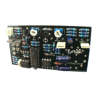
Important notes If you’re using any of our footswitch daughterboards, DOWNLOAD THE DAUGHTERBOARD DOCUMENT • Download and read the appropriate build document for the daughterboard as well as this one BEFORE you start. • DO NOT solder the supplied Current Limiting Resistor (CLR) to the main circuit board even if there is a place for it. - Page 3 Schematic + BOM 100n BIAS 100KB 100K DEPTH 10KB LEVEL 100KB SPEED 10KA 100n 470n SHAPE 100K TRIM 100K TRIM 100K 100u elec 100u elec 3P4T ROTARY 470K 10u elec DPDT ON-ON 470R 10u elec CLR (2K2) 2N3819* 2N3906 2N3904 *We’ve tried other FETs and they all worked absolutely fine - 180K...
- Page 4 The power and signal pads on the PCB conform to The rotary switch has a small plastic locator tab on the FuzzDog Direct Connection format, so can be the top side - line this up with the symbol on the paired with the appropriate daughterboard for pcb.
- Page 5 Test the board! Check the relevant daughterboard document for more info before you undertake this stage. UNDER NO CIRCUMSTANCES will troubleshooting help be offered if you have skipped this stage. No exceptions. Once you’ve finished the circuit it makes sense to test is before starting on the switch and LED wiring.
- Page 6 SETTING UP You have two trimmers to set. Pin 3 of the depth pot is the best place to attach your probe if you’re using a scope. SHAPE This adjusts the shape of the triangle wave. If you have an oscilloscope now’s the time to fire it up.
- Page 7 Wire it up - with battery (if using a daughterboard please refer to the relevant document) BOARD BOARD INPUT BOARD BOARD BOARD BOARD LED+ BOARD BOARD BATTERY This circuit is standard, Negative GND. Your power supply should be Tip Negative / Sleeve Positive. That’s the same as your standard pedals (Boss etc), and you can safely daisy-chain your supply to this pedal.
-
Page 8: Drilling Template
3 mm 35mm This template is a rough guide only. You should ensure correct marking of your enclosure before drilling. You use this template at your own risk. Pedal Parts Ltd can accept no responsibility for incorrect drilling of enclosures. FuzzDog.co.uk...
Need help?
Do you have a question about the Gristleiser and is the answer not in the manual?
Questions and answers