
Subscribe to Our Youtube Channel
Related Manuals for FuzzDog Hot Snake Boost


Summary of Contents for FuzzDog Hot Snake Boost
- Page 1 Hot Snake Boost Red Hot Treble Boost ...Careful now Contents of this document are ©2018 Pedal Parts Ltd. No reproduction permitted without the express written permission of Pedal Parts Ltd. All rights reserved.
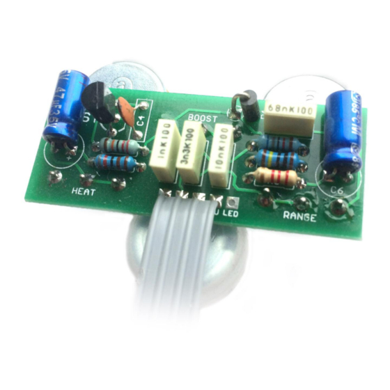
- Page 2 Schematic + BOM 220K 1N4001 2N2222** 2K2 (CLR) BOOST 10KB 47u elec HEAT 47u elec RANGE 500KA *R4 is an optional anti-pop resistor. ** See notes overleaf regarding pinout/orientation before placing.
- Page 3 Check the separate datasheet if sourcing your own parts. daughterboard document for details. If you’re building a FuzzDog kit, your Be very careful when soldering the diode transistors will be one of the following: and transistor. They’re very sensitive to heat.
- Page 4 Test the board! BATTERY 9V GND Your nice, new circuit board INCLUDING WIRED POTS!!!! UNDER NO CIRCUMSTANCES will troubleshooting help be offered if you have skipped this stage. No exceptions. Once you’ve finished the circuit it makes sense to test is before starting on the switch and LED wiring.
- Page 5 Wire it up (if using a daughterboard please refer to the relevant document) BOARD BOARD INPUT BOARD BOARD BOARD BOARD LED+ BOARD BOARD BATTERY Wiring shown above will disconnect the battery when you remove the jack plug from the input, and also when a DC plug is inserted. The Board GND connections don’t all have to directly attach to the board.
-
Page 6: Drilling Template
32mm 21mm This template is a rough guide only. You should ensure correct marking of your enclosure before drilling. You use this template at your own risk. Pedal Parts Ltd can accept no responsibility for incorrect drilling of enclosures. FuzzDog.co.uk...
Need help?
Do you have a question about the Hot Snake Boost and is the answer not in the manual?
Questions and answers