
Subscribe to Our Youtube Channel
Related Manuals for FuzzDog Klone V4


Summary of Contents for FuzzDog Klone V4
- Page 1 Klone Ultimate box of transparent overdrive Contents of this document are ©2017 Pedal Parts Ltd. No reproduction permitted without the express written permission of Pedal Parts Ltd. All rights reserved.
-
Page 2: Important Notes
Important notes If you’re using any of our footswitch daughterboards, DOWNLOAD THE DAUGHTERBOARD DOCUMENT • Download and read the appropriate build document for the daughterboard as well as this one BEFORE you start. • DO NOT solder the supplied Current Limiting Resistor (CLR) to the main circuit board even if there is a place for it. - Page 3 Schematic BOM is for Silver Pony version. *There are a few value substitutions we Gold version values shown in blue. recommend - see next page for details. If using a 7660 for IC3 you need one with an **R28 is the current limiter for the LED. This S suffix.
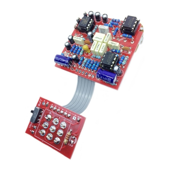
- Page 4 PCB Layout ©2017 Pedal Parts Ltd. PART SUBSTITUTIONS The circuit benefits from some extra bass in both the gain and clean sections: 100n (clean) 120 - 150n (gain) The Tone (Treble) control has a more useful range if you increase to 6n8 or 8n2.
- Page 5 The best way to get the pots lined up is to first solder one pin of each. Once they’re tacked in place adjust them so they’re straight and check to see if the heights line up. If not, melt that soldered joint and adjust. Once you’re happy all the pots are aligned you can solder in the other legs.
- Page 6 Keep it simple... No charge... No buffer... You can eliminate the charge pump if you If you prefer to keep things True Bypass and prefer. It’s only in there to give IC2 more you want to use your own daughterboard you headroom and avoid clipping.
- Page 7 Wire it up - switching board...
- Page 8 Wire it up - true bypass...
- Page 9 Wire it up - buffered bypass Sorry, it’s not particularly elegant, but pad 1 from the main board should connect directly to the footswitch lug as shown. It should actually work fine without this wire, but it follows the original in that it grounds the output of the gain section on bypass.
- Page 10 What’s going on with those switches? Here’s what’s connected to what... BUFFERED TRUE BYPASS Jack Jack...
-
Page 11: Drilling Template
Wiggle room = good! 32mm This template is a rough guide only. You should ensure correct marking of your enclosure before drilling. You use this template at your own risk. Pedal Parts Ltd can accept no responsibility for incorrect drilling of enclosures. FuzzDog.co.uk...
Need help?
Do you have a question about the Klone V4 and is the answer not in the manual?
Questions and answers