
Subscribe to Our Youtube Channel
Related Manuals for FuzzDog Clay Jones OD V2


Summary of Contents for FuzzDog Clay Jones OD V2
- Page 1 Clay Jones OD Super-rare, silly-expensive boutique Tube Screamer Contents of this document are ©2016 Pedal Parts Ltd. No reproduction permitted without the express written permission of Pedal Parts Ltd. All rights reserved.
- Page 2 Schematic +BOM OPA2134 510K Q1,2 BC546B*** 220n D1,2 3mm red LED ‡ 220n** Jumper 1N4148 or 1N4001 220n** 100n TONE 20KB/W 220R DRIVE 510K 100u LEVEL 100KB *R22 - optional anti-pop resistor not on original. 100R **C5 and C9 are polarised tantalums on a normal Tube empty Screamer.
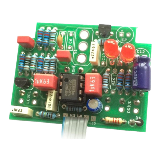
- Page 3 The power and signal pads on the PCB conform to the FuzzDog Direct Connection format, so can be paired with the appropriate daughterboard for quick and easy offboard wiring. Be very careful when soldering the LED, transistors and diodes. They’re very sensitive to heat.
- Page 4 Test the board! BATTERY 9V GND Your nice, new circuit board INCLUDING WIRED POTS!!!! UNDER NO CIRCUMSTANCES will troubleshooting help be offered if you have skipped this stage. No exceptions. Once you’ve finished the circuit it makes sense to test is before starting on the switch and LED wiring.
- Page 5 Wire it up - with battery (if using a daughterboard please refer to the relevant document) BOARD BOARD INPUT BOARD BOARD BOARD BOARD LED+ BOARD BOARD BATTERY This circuit is standard, Negative GND. Your power supply should be Tip Negative / Sleeve Positive. That’s the same as your standard pedals (Boss etc), and you can safely daisy-chain your supply to this pedal.
- Page 6 Wire it up - DC only version (if using a daughterboard please refer to the relevant document) BOARD BOARD INPUT BOARD BOARD BOARD BOARD LED+ BOARD BOARD This circuit is standard, Negative GND. Your power supply should be Tip Negative / Sleeve Positive. That’s the same as your standard pedals (Boss etc), and you can safely daisy-chain your supply to this pedal.
- Page 7 Drilling template Recommended drill sizes: Pots Jacks 10mm Hammond 1590B Footswitch 12mm DC Socket 12mm 60 x 111 x 31mm It’s a good idea to drill the pot and toggle switch holes 1mm bigger if you’re board-mounting them. Wiggle room = good! 32mm 21mm This template is a rough guide only.
Need help?
Do you have a question about the Clay Jones OD V2 and is the answer not in the manual?
Questions and answers