
Subscribe to Our Youtube Channel
Related Manuals for FuzzDog FuzzPup Rodent


Summary of Contents for FuzzDog FuzzPup Rodent
- Page 1 Rodent A big, fat bitey Rat in a shrew’s body Contents of this document are ©2018 Pedal Parts Ltd. No reproduction permitted without the express written permission of Pedal Parts Ltd. All rights reserved.
- Page 2 IMPORTANT Before you start... Grab the general build doc that covers all FuzzPup builds. Most of the information you need for this build is in there. Read it? OK, carry on. uzzPups Lovely little boxes of joy with a totally standardised build pattern Contents of this document are ©2016 Pedal Parts Ltd.
- Page 3 Schematic + BOM The PCB is designed to take 1/8W (0.125W) resistors. You can use 1/4W if you wish, but you’ll have to position them 560R 100p upright. Make sure they’re bent enough 47R* that you’ll have plenty of clearance in your enclosure.
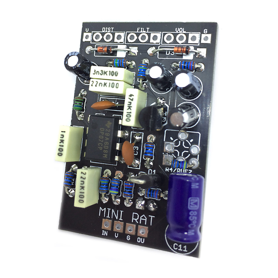
- Page 4 Unlike most of our FuzzPup PCBs the Rat doesn’t have pads for the jack connections. You have to use to daughterboard for those. It’s also a little wider at 30mm, so there’s not so much room for wire access once it’s built. If you aren’t adding the Ruez response mod trimmer, place R4 as shown above.
- Page 5 The following pages show the FuzzPup BigFluff being assembled. The process is identical . Wire up your pots If you’re using the pot daughterboard you need to allow some slack in the wires attaching it to the main PCB. About an inch is a good length. We recommend wiring on the top side of the main PCB rather than underneath as it’s easier to guide the wires on final assembly, and they’re less likely to get snagged up under the boards.
- Page 6 Assembly #1 This is where the *fun* starts. As this PCB is slightly different to our normal FuzzPup range in not having jack connections and being a bit wider, you need to take a little more care with assembly. Get your hardware in place in the enclosure and wire it up, leaving plenty of slack where it’ll join the daughterboard.
- Page 7 Assembly #2 Now attach the wires to the daughterboard. Don’t forget your current limiting resistor. Push the LED into its pads in the board and bend the legs out slightly to keep in in place. You’ll push this through into final position once the board is soldered to the footswitch.
- Page 8 Assembly #3 Now for the fiddly bit. Put your pots into position. No need to tighten them up yet, but no harm if you do. Locate the header pins on the main PCB into the CI, V, G, CO pads on the daughterboard and bring both boards down into the enclosure.
- Page 9 ...and BOOM! Hopefully not literally. One fully assembled mini Rat. If you have a top-mounted DC socket get it in there and wire it up with the V and G pads in the top corners of the main PCB. Enjoy!
- Page 10 FuzzDog.co.uk...
Need help?
Do you have a question about the FuzzPup Rodent and is the answer not in the manual?
Questions and answers