
Subscribe to Our Youtube Channel
Related Manuals for FuzzDog GimpFX Ultr-Fk


Summary of Contents for FuzzDog GimpFX Ultr-Fk
- Page 1 GimpFX Ultr-Fk More sludgy bass fuzz than you can shake a thigh-bone at Contents of this document are ©2015 Pedal Parts Ltd. No reproduction permitted without the express written permission of Pedal Parts Ltd. All rights reserved.
- Page 2 Schematic Switch marked in blue above is the optional Notch Shift control, which is SPDT ON-OFF-ON. This is not required if using the SHIFT pot. Switch marked in orange is the MORE footswitch on the daughterboard. Q1,3 BC550 2N5088 100K 3mm OrangeLED 1N4001 10n**...
- Page 3 Be very careful when soldering the diodes, LED and transistors. They’re very sensitive to heat. You should use some kind of heat sink (crocodile clip or reverse action tweezers) on each leg as you solder them. Keep exposure to heat to a minimum (under 2 seconds). The striped leg (cathode) of the diodes go into the square pads.
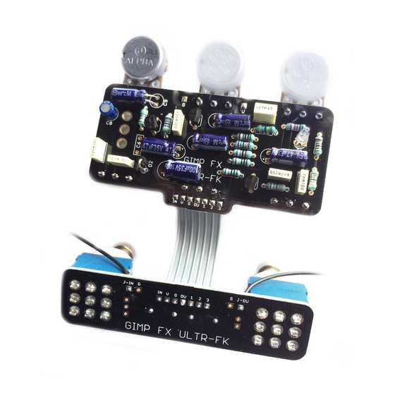
- Page 4 Ensure you mount the footswitches on the right side of the daughterboard. It’s clearly marked. Otherwise your ribbon cable connections won’t line up. The boards are designed for a 7-way ribbon cable connection between them, but you can use any wire you want.
- Page 5 WIRING Couldn’t be much easier really. Once you have the daughterboard and main circuit connected (hopefully you’ve used a 7-way ribbon cable for extra simplicity and neatness), there are only six wires to connect as shown below.
- Page 6 Drilling template Ultr-Fk Recommended drill sizes: Pots Hammond 1590BB Jacks 10mm Footswitch 12mm 91 x 116 x x 31mm DC Socket 12mm Toggle Switch 6-7mm It’s a good idea to drill the holes for the pots 8mm to give yourself some wiggle room unless you’re a drill ninja 3 mm...
Need help?
Do you have a question about the GimpFX Ultr-Fk and is the answer not in the manual?
Questions and answers