
Subscribe to Our Youtube Channel
Related Manuals for FuzzDog Tube Screamer v4.0


Summary of Contents for FuzzDog Tube Screamer v4.0
- Page 1 Tube Screamer v4.0 Tube Screamer TS808 / TS9 Contents of this document are ©2016 Pedal Parts Ltd. No reproduction permitted without the express written permission of Pedal Parts Ltd. All rights reserved.
- Page 2 Schematic + BOM 4558 510K Q1,2 2N3904 .22u tant D1,2 1N4148 See bass mod Jumper* (4.7u) 1N4001 .22u tant TONE 20KW*** 220R 100n DRIVE 500KA 510K LEVEL 100KA (100K) 100u See bass mod SPDT** 100R (470R) Parts listed are for the TS808 version. For TS9 substitute parts in blue.
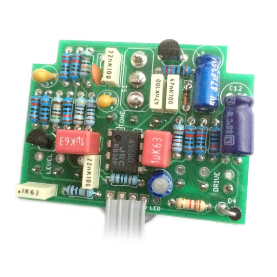
- Page 3 The power and signal pads on the PCB conform to the FuzzDog Direct Connection format, so can be paired with the appropriate daughterboard for quick and easy offboard wiring. Check the separate daughterboard document for details. Be very careful when soldering the transistors and diodes.
- Page 4 Test the board! BATTERY 9V GND Your nice, new circuit board INCLUDING WIRED POTS!!!! UNDER NO CIRCUMSTANCES will troubleshooting help be offered if you have skipped this stage. No exceptions. Once you’ve finished the circuit it makes sense to test is before starting on the switch and LED wiring.
- Page 5 Wire it up BOARD BOARD INPUT BOARD BOARD BOARD BOARD LED+ BOARD BOARD BATTERY Wiring shown above will disconnect the battery when you remove the jack plug from the input, and also when a DC plug is inserted. The Board GND connections don’t all have to directly attach to the board. You can run a couple of wires from the DC connector, one to the board, another to the IN jack, then daisy chain that over to the OUT jack.
- Page 6 Drilling template Recommended drill sizes: No Switch Pots Jacks 10mm Footswitch 12mm DC Socket 12mm Hammond 1590B Toggle Switch 60 x 111 x 31mm It’s a good idea to drill the pot and toggle switch holes 1mm bigger if you’re board-mounting them.
- Page 7 Drilling template Recommended drill sizes: with Switch Pots Jacks 10mm Footswitch 12mm DC Socket 12mm Hammond 1590B Toggle Switch 60 x 111 x 31mm It’s a good idea to drill the pot and toggle switch holes 1mm bigger if you’re board-mounting them.
Need help?
Do you have a question about the Tube Screamer v4.0 and is the answer not in the manual?
Questions and answers