
Subscribe to Our Youtube Channel
Related Manuals for FuzzDog 7 of Dwarves Auto Wah


Summary of Contents for FuzzDog 7 of Dwarves Auto Wah
- Page 1 7 of Dwarves Auto Wah Four knobs of funkin’ sweet auto filtering Contents of this document are ©2015 Pedal Parts Ltd. No reproduction permitted without the express written permission of Pedal Parts Ltd. All rights reserved.
- Page 2 Schematic + BOM Values in blue are improvements on the original and are supplied with the kit. 330R D4 should be reversed or 330R you can just leave it out. D1-3 1N4148 2K2 (CLR) D4-5 1N4001 330R 330R LM13700 220n LM324 1u elec 78L05...
- Page 3 General Notes The power and signal pads on the PCB conform to the FuzzDog Direct Connection format, so can be paired with the appropriate daughterboard for quick and easy offboard wiring Be very careful when soldering the LED, diodes, transistors and voltage regulator (IC3).
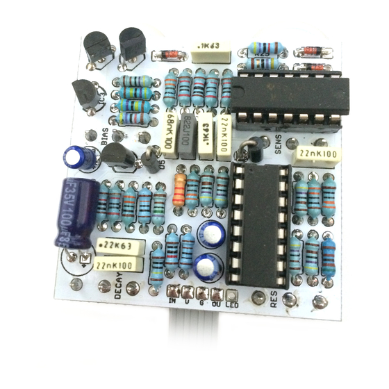
- Page 4 Test the board! BATTERY 9V GND Your nice, new circuit board INCLUDING WIRED POTS!!!! UNDER NO CIRCUMSTANCES will troubleshooting help be offered if you have skipped this stage. No exceptions. Battery clip is supplied to test the circuit. Power supply is recommended when using the finished delay as it will EAT batteries.
- Page 5 Wire it up - DC only version (if using a daughterboard please refer to the relevant document) BOARD BOARD INPUT BOARD BOARD BOARD BOARD LED+ BOARD BOARD This circuit is standard, Negative GND. Your power supply should be Tip Negative / Sleeve Positive. That’s the same as your standard pedals (Boss etc), and you can safely daisy-chain your supply to this pedal.
- Page 6 BOARD LED+ BOARD BOARD Just because the BATTERY FuzzDog enclosure won’t take a battery, there’s nothing stopping you using a bigger box. This circuit is standard, Negative GND. Your power supply should be Tip Negative / Sleeve Positive. That’s the same as your standard pedals (Boss etc), and you can safely daisy-chain your supply to this pedal.
- Page 7 Drilling template Recommended drill sizes: Pots Jacks 10mm Hammond 1590B Footswitch 12mm DC Socket 12mm 60 x 111 x 31mm It’s a good idea to drill the holes for the pots 1mm bigger to give yourself some wiggle room, unless you’re a drill ninja.
Need help?
Do you have a question about the 7 of Dwarves Auto Wah and is the answer not in the manual?
Questions and answers