
Subscribe to Our Youtube Channel
Related Manuals for FuzzDog The Gimp


Summary of Contents for FuzzDog The Gimp
- Page 1 The Gimp Germanium fuzz +++ Contents of this document are ©2015 Pedal Parts Ltd. No reproduction permitted without the express written permission of Pedal Parts Ltd. All rights reserved.
- Page 2 Schematic + BOM 10 elec 220K 100n 470R 2u2 elec** SANITY 10u elec GIRTH 500KC ‡ 220K 10u elec CHOKE 10KB 10KB Q1,2 PNP Ge*** THRUST 2K2* 2N3904 GRUNT 10KB *2 x CLRs are required on the daughterboard. Use whatever you prefer as your normal LED current limiter.
- Page 3 Be very careful when soldering the diodes, LED and transistors. They’re very sensitive to heat. You should use some kind of heat sink (crocodile clip or reverse action tweezers) on each leg as you solder them. Keep exposure to heat to a minimum (under 2 seconds). The long leg (anode) of the electrolytic capacitors go into the square pads.
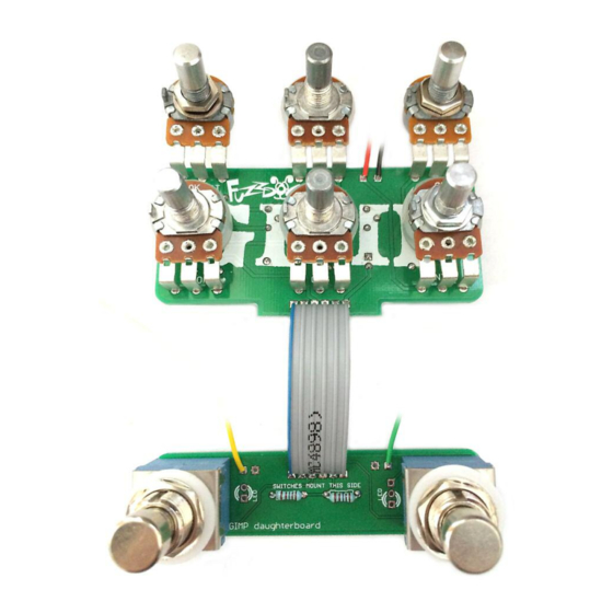
- Page 4 Ensure you mount the footswitches on the right side of the daughterboard. It’s clearly marked. Otherwise your ribbon cable connections won’t line up. The boards are designed for a 6-way ribbon cable connection between them, but you can use any wire you want.
- Page 5 Drilling template The Gimp Recommended drill sizes: Pots Hammond 1590BB Jacks 10mm Footswitch 12mm 91 x 116 x x 31mm DC Socket 12mm Toggle Switch 6-7mm It’s a good idea to drill the holes for the pots 8mm to give yourself some wiggle room unless you’re a drill ninja...
Need help?
Do you have a question about the The Gimp and is the answer not in the manual?
Questions and answers