
Related Manuals for JYTEK PCIe-5211


Summary of Contents for JYTEK PCIe-5211
- Page 1 PCIe/PXIe-5211 Counter/Timer Module User Manual User Manual Version: V1.6.2 Revision Date: Oct . 09, 2021...
-
Page 2: Table Of Contents
3.1 System Requirements..................11 3.2 System Software.....................11 3.3 C# Programming Language................11 3.4 PCIe/PXIe-5211 Series Hardware Driver............12 3.5 Install the SeeSharpTools from JYTEK............12 3.6 Running C# Programs in Linux................12 4.Operating PCIe/PXIe-5211..................14 4.1 Quick Start...................... 14 4.2 Digital I/O Operations..................14 4.3 Counter Measurement Operations..............15... - Page 3 5.Using PCIe/PXIe-5211 in Other Software..............61 5.1 C++........................61 6.About JYTEK......................62 6.1 JYTEK China.....................62 6.2 JYTEK Korea and JYTEK In Other Countries............ 62 6.3 JYTEK Hardware Products................62 6.4 JYTEK Software Platform................63 6.5 JYTEK Warranty and Support Services............63 7.Statement.........................
- Page 4 Table 2 Counter/Timer Specifications..............6 Table 3 Other Specifications.................. 7 Table 4 Pin Defination.................... 9 Table 5 Counter Input/Output Default Routing...........10 Table 6 Supported Linux Versions................11 Table 7 SSI Connector Pin Assignment for PCIe-5211..........59 Table 8 Relationship between switch position and slot number......60...
-
Page 5: Overview
The device utilizes a high-throughput PCI Express bus and multi-core optimized drivers and application software to provide high-performance capabilities. Please check with JYTEK website for the latest 5211 series offering. 1.2 Main Features 8 channels of counter ... -
Page 6: Learn By Example
TXCO: Temperature Compensate X'tal (crystal) Oscillator 1.4 Learn by Example JYTEK has added Learn by Example in this manual. We provide many sample programs for this device. Please download and install the sample programs for this device. You can download a JYPEDIA excel file from our web www.jytel,com. - Page 7 Tip: PCIe/PXIe-5211 also has the counter output capability. If you do not have a signal source, you can use the outputs of PCIe/PXIe-5211 as the signal source. In this case you need first run example program Counter Output--> Winform CO Continuous Wrapping to generate the output. PCIe/PXIe-5211 | jytek.com...
-
Page 8: Hardware Specifications
The system block diagram of PCIe/PXIe-5211 series is shown in Figure 2. It is mainly composed of one DIO module and eight Counter/Timer modules, providing digital input, digital output, counter input, counter output functions. JYTEK's FPGA-based driver FirmDrive provides a stable and efficient PCIe / PXIe / USB interface. PCIe/PXIe-5211 |... -
Page 9: Digital Io Specifications
2.2 Digital IO Specifications Table 1 Digital IO Specifications PCIe/PXIe-5211 | jytek.com... -
Page 10: Counter/Timer Specifications
2.3 Counter/Timer Specifications Table 2 Counter/Timer Specifications PCIe/PXIe-5211 | jytek.com... -
Page 11: Other Specifications
2.4 Other Specifications Table 3 Other Specifications PCIe/PXIe-5211 | jytek.com... -
Page 12: Front Panel And Pin Definition
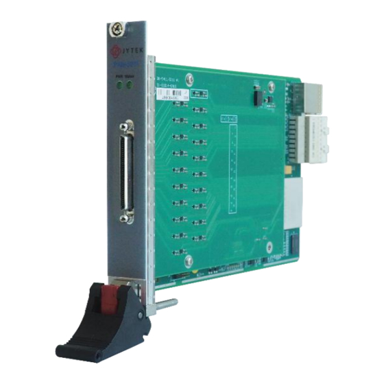
2.5 Front Panel and Pin Definition Figure 3 Front Pannel PCIe/PXIe-5211 | jytek.com... - Page 13 Table 4 Pin Defination PCIe/PXIe-5211 | jytek.com...
-
Page 14: Default Routing For Counter Input/Output Signals
2.6 Default Routing for Counter Input/Output Signals All counter input and output terminals are routed to a certain PFI by default as shown in Table 5. Table 5 Counter Input/Output Default Routing PCIe/PXIe-5211 | jytek.com | 10... -
Page 15: Software
Microsoft Windows: Windows 7 32/64 bit, Windows 10 32/64 bit. Linux Kernel Versions: There are many Linux versions. It is not possible JYTEK can support and test our devices under all different Linux versions. JYTEK will at the best support the following Linux versions. -
Page 16: Pcie/Pxie-5211 Series Hardware Driver
If you want to use your own Linux development system other than MonoDevelop, you can do it by using our Linux driver. However, JYTEK does not have the capability to support the Linux applications. JYTEK completely relies upon Microsoft to PCIe/PXIe-5211 | jytek.com... - Page 17 Windows and Linux using MonoDevelop. PCIe/PXIe-5211 | jytek.com | 13...
-
Page 18: Operating Pcie/Pxie-5211
This chapter provides the operation guides for PCIe/PXIe-5211, including Timer and programmable I/O interface, etc. JYTEK provides extensive examples, on-line help and documentation to assist you to use the PCIe/PXIe-5211 module. JYTEK strongly recommends you go through these examples before writing your own application. In many cases, an example can also be a good starting point for a user application. -
Page 19: Counter Measurement Operations
4.5.2. 4.3.1 Edge Counting The counter counts the number of active edges of input signal. Default, the input signal must be connected to Counter Source terminal. Set JY5211CITask.Type to CIType.EdgeCounting to use this function. PCIe/PXIe-5211 | jytek.com | 15... - Page 20 Figure 6. Figure 6 Buffered Edge Counting with Explicit Sample Clock To configure the counter to work in this mode, set JY5211CITask.Mode to CIMode.Finite or CIMode.Continuous, and set JY5211CITask.SampleClock.Source to CISampleClockSource.Internal or CISampleClockSource.External. PCIe/PXIe-5211 | jytek.com | 16...
- Page 21 Pause trigger is used to pause counting when the input signal is active depending on active polarity configuration as shown in Figure 8. Default, the Pause Trigger signal must be connected to Counter Gate terminal. Figure 8 Pause Trigger PCIe/PXIe-5211 | jytek.com | 17...
- Page 22 When the counting value reaches the specified threshold, the counter will generate a pulse. To change the threshold, using following property: JY5211CITask.EdgeCounting.OutEvent.Threshold Terminals To change the terminal of signals instead of using its default value as shown in chapter 2.6, using following properties: PCIe/PXIe-5211 | jytek.com | 18...
- Page 23 The table in the sample program is a connection diagram for your convenience. Click Start, and the result is shown by Count. In this example Count increases by 1 every second for a 1Hz squarewave. PCIe/PXIe-5211 | jytek.com | 19...
- Page 24 Direction is set by Direction. There are three sample clock sources in PCIe/PXIe-5211 set by Sample Clock Source: Internal, Implicit and External. Click Start to start counting by rising edge. The result is shown below: PCIe/PXIe-5211 | jytek.com | 20...
- Page 25 Change the Sample Clock Source to Implicit: Figure 13 Edge Counting With Implicit Clock The numbers are stored in a buffer Counts. The counter values are different as before because of the change from Sample Clock Source. PCIe/PXIe-5211 | jytek.com | 21...
-
Page 26: Pulse Measurement
2) Finite/Continuous Mode with Explicit Sample Clock The counting value of the duration of the high-level or low-level is stored into the buffer on each rising edge of the sample clock, as shown in Figure 15. PCIe/PXIe-5211 | jytek.com | 22... - Page 27 To configure the counter to work in this mode, set JY5211CITask.Mode to CIMode.Finite or CIMode.Continuous, and set JY5211CITask.SampleClock.Source to CISampleClockSource.Implicit. Timebase By default, the counter uses the onboard 200MHz timebase to measure pulses. Use the property JY5211CITask.PulseMeas.Timebase to configure the timebase. PCIe/PXIe-5211 | jytek.com | 23...
- Page 28 Single Mode Open Counter Input-->Winform CI Single Pulse, set the following numbers as shown: Figure 17 Pulse Measure In Single Mode The table in the sample program is a connection diagram for your convenience. PCIe/PXIe-5211 | jytek.com | 24...
- Page 29 The numbers show the duration of High/Low Level in one signal period and match the duty cycle set before. Finite/Continuous Mode Change the frequency of the squarewave to 50 Hz. Open Counter Input-->Winform CI Finite/Continuous Pulse, set the following numbers as shown: PCIe/PXIe-5211 | jytek.com | 25...
- Page 30 The table in the sample program is a connection diagram for your convenience. Click Start to begin the finite/continuous pulse measurement. The result is shown below: Figure 20 Pulse Measure Values In Finite Mode PCIe/PXIe-5211 | jytek.com | 26...
- Page 31 The numbers show the duration of High/Low Level in one signal period and match the duty cycle set before. Please refer to Learn by Examples 4.3.1 Finite/Continuous Mode about the difference between Explicit and Implicit. PCIe/PXIe-5211 | jytek.com | 27...
-
Page 32: Frequency Measurement
(�1) of the signal, and the number of rising edges of timebase (�2) during those full periods. These two values are stored into the buffer on each rising edge of the sample clock, as shown in Figure 21. PCIe/PXIe-5211 | jytek.com | 28... - Page 33 ) values according to the fomular and return the result to the user. � � + � � ℎ � To configure the counter to work in this mode, set JY5211CITask.Mode to CIMode.Finite or CIMode.Continuous, and set JY5211CITask.SampleClock.Source to CISampleClockSource.Implicit. PCIe/PXIe-5211 | jytek.com | 29...
- Page 34 Set the signal source Ch1’s output to squarewave signal (f=50Hz, Duty � � =0v). Single Mode Open Counter Input-->Winform CI Single Frequency and click Start. The result is shown below by Frequency (Hz): Figure 22 Frequency Measure In Single Mode PCIe/PXIe-5211 | jytek.com | 30...
- Page 35 The table in the sample program is a connection diagram for your convenience. Please refer to Learn by Examples 4.3.1 Finite/Continuous Mode about the difference between Explicit and Implicit. Click Start and it will show the frequency 50 as set in the signal source. PCIe/PXIe-5211 | jytek.com | 31...
- Page 36 Figure 24 Frequency Measure Values In Single Mode PCIe/PXIe-5211 | jytek.com | 32...
-
Page 37: Period Measurement
Figure 25 Period Measure In Single Mode The table in the sample program is a connection diagram for your convenience. The result of Period (s) shows the correspond to the frequency set before. PCIe/PXIe-5211 | jytek.com | 33... - Page 38 Start. The result is shown below by Period(s). Figure 26 Period Measure In Finite Mode The table in the sample program is a connection diagram for your convenience. The result of Period(us) shows the correspond to the frequency set before. PCIe/PXIe-5211 | jytek.com | 34...
-
Page 39: Two-Edge Separation
2) Finite/Continuous Mode with Explicit Sample Clock: The counting values of rising edges of timebase between first signal and second signal are stored into buffer on each rising edge of the sample clock, as shown in Figure 28. PCIe/PXIe-5211 | jytek.com | 35... - Page 40 Figure 29. Figure 29 Two-Edge Seperation with Implicit Sample Clock PCIe/PXIe-5211 | jytek.com | 36...
- Page 41 Open Counter Input-->Winform CI Single Two-Edge Separation and click Start. The result is shown below by First Separation and Second Separation, which represent the number of rising edges on the timebase difference between the rising edges of the two signals: PCIe/PXIe-5211 | jytek.com | 37...
- Page 42 Start. The result is shown below by First Separation(s) and Second Separation(s), which represent the number of rising edges on the timebase difference between the rising edges of the two signals: Figure 31 Two-Edge Separation Measure In Finite Mode PCIe/PXIe-5211 | jytek.com | 38...
- Page 43 Figure 32 Two-Edge Separation Measure In Continuous Mode The table in the sample program is a connection diagram for your convenience. The result in this picture is similar to the result in Single Mode before. PCIe/PXIe-5211 | jytek.com | 39...
-
Page 44: Quadrature Encoder
A signal; when B signal leads A signal, the counter decreases the count value the rising edge and falling edge of A signal as shown in Figure 34. Figure 34 Quadrature Encoder x2 Mode PCIe/PXIe-5211 | jytek.com | 40... - Page 45 To configure the counter to work in this mode, set JY5211CITask.Mode to CIMode.Single. 2) Finite/Continuous Mode with Explicit Sample Clock The count value is stored into the buffer on each rising edge of the sample clock, as shown in Figure 36. PCIe/PXIe-5211 | jytek.com | 41...
- Page 46 Figure 37. Figure 37 Quadrature Encoder x4 with Implicit Sample Clock To configure the counter to work in this mode, set JY5211CITask.Mode to CIMode.Finite or CIMode.Continuous, and set JY5211CITask.SampleClock.Source to CISampleClockSource.Implicit. PCIe/PXIe-5211 | jytek.com | 42...
- Page 47 Encoding Type is set by Encode Type (x1, x2, x4). When the Encoding type is changed from x1 to x2 and x4, you can see the rising speed of Count is twice and four times than x1Mode. PCIe/PXIe-5211 | jytek.com | 43...
- Page 48 Finite/Continuous Mode Open Counter Input--> Winform CI Single Quadrature Encoder and click Start. The result is shown below by Count. Figure 39 Quadrature Encoder In Finite Mode Figure 40 Quadrature Encoder In Continuous Mode PCIe/PXIe-5211 | jytek.com | 44...
- Page 49 Encoding Type is set by Encode Type (x1, x2, x4). When the encode type is changed from x1 to x2 and x4, you can see the rising speed of Count is twice and four times than x1Mode. PCIe/PXIe-5211 | jytek.com | 45...
-
Page 50: Two-Pulse Encoder
To configure the counter to work in this mode, set JY5211CITask.Mode to CIMode.Single. 2) Finite/Continuous Mode with Explicit Sample Clock The count value is stored into the buffer on each rising edge of the sample clock, as shown in Figure 42. PCIe/PXIe-5211 | jytek.com | 46... - Page 51 In implicit mode, the signal active edge as the implicit sample clock edge. The count value is stored into the buffer on the rising edge of A signal and B signal, as shown in Figure 43. Figure 43 Two-Pulse Encoder with Implicit Sample Clock PCIe/PXIe-5211 | jytek.com | 47...
- Page 52 Set the signal source Ch1’s to squarewave signal (f=10Hz, Phase=0˚) and Ch2’s output to squarewave signal (f=5Hz, Phase=90˚). Single Mode Open Counter Input-->Winform CI Single Two-Pulse Encoder and set the numbers as shown. Figure 44 Two-Pulse Encoder In Single Mode PCIe/PXIe-5211 | jytek.com | 48...
- Page 53 The table in the sample program is a connection diagram for your convenience. Click Start and you can see a group of rising numbers in position, which follows the counting rules explained in4.3.7. PCIe/PXIe-5211 | jytek.com | 49...
-
Page 54: Counter Generation Operations
If the number of pulses is set to -1, the pulses will be output continuously until requesting to stop. In this case, it is allowed to change the frequency and duty cycle on the fly. The timing diagram is shown as Figure 47. PCIe/PXIe-5211 | jytek.com | 50... - Page 55 Each set of pulses can be configured in different ways: Frequency, Duty cycle and Number of pulses High time, Low time and Number of pulses High ticks, Low ticks and Number of pulses PCIe/PXIe-5211 | jytek.com | 51...
-
Page 56: Learn By Examples
2.6, using following properties: JY5211COTask.OutputTerminal – Signal output terminal. Learn by Examples Single Mode Open Counter Output-->Winform CO Single and click Start and set the numbers as follow: Figure 49 CO In Single Mode PCIe/PXIe-5211 | jytek.com | 52... - Page 57 Open Counter Output-->Winform CO Finite and click Start and set the numbers as follow: Figure 50 CO In Finite Mode The table in the sample program is a connection diagram for your convenience. PCIe/PXIe-5211 | jytek.com | 53...
-
Page 58: Clocks
When using this clock, PXIe-5211 can provide multi-card synchronization. 3) External Reference Clock An external reference clock is a clock provided by user through terminal PXIe-DSTARA. To use an external reference clock, the user needs to specify its frequency. PCIe/PXIe-5211 | jytek.com | 54... -
Page 59: Sample Clock
To use the internal sample clock, configure as follows: 1. Set JY5211CITask.SampleClock.Source to CISampleClockSource.Internal 2. Set JY5211CITask.SampleClock.Internal.Rate to specify sample rate External External sample clock refers to an external signal input from a terminal as the sample clock PCIe/PXIe-5211 | jytek.com | 55... -
Page 60: Timebase
Internal 200MHz: - Same signal as the 200MHz base clock generated by PLL. Internal 5MHz – Generated by dividing down the 200MHz timebase. Internal 100kHz – Generated by dividing down the 200MHz timebase. External - Use a signal on a terminal as the timebase PCIe/PXIe-5211 | jytek.com | 56... -
Page 61: Start Trigger
5 V. To change the logic level by the following properties: 1. Set property Device.LogicLevel to target logic level. Call method Device.Commit() to activate the configuration. Note: Logic Level configuration will be applied to all PFIs PCIe/PXIe-5211 | jytek.com | 57... -
Page 62: Multi-Card Synchronization
1. Set each task on different card as Master or Slave. Only one master is allowed. 2. Set the reference clock source of master card and slave card to PXIe_CLK100. Refer to 4.5.1 for more information. PCIe/PXIe-5211 | jytek.com | 58... -
Page 63: System Synchronization Interface (Ssi)For Pcie Modules
PCIe modules. One PCIe module is designated as the master module and the other PCIe modules are designated as the slave modules. Figure 54 SSI Connector in PCIe-5211 Table 7 SSI Connector Pin Assignment for PCIe-5211 PCIe/PXIe-5211 | jytek.com | 59... - Page 64 4.10 DIP Switch in PCIe-5211 PCIe-5211 series modules have a DIP switch. The card number can be adjusted manually by turning the DIP switch, which is used to identify the module with different slot positions. For example, if you want to set the card number to 3, you could turn the position 2 and 1 of the DIP switch to the ON position and the orthers to OFF.
- Page 65 5. Using PCIe/PXIe-5211 in Other Software While JYTEK’s defalt application platform is Visual Studio, the programming language is C#, we recognize there are other platforms that are either becoming very popular or have been widely used in the data acquisition applications. Among them are C++ etc.
- Page 66 6. About JYTEK 6.1 JYTEK China Founded in June, 2016, JYTEK China is a leading Chinese test & measurement company, providing complete software and hardware products for the test and measurement industry. The company is a joint venture between Adlink Technologies and a group of experienced professionals form the industry.
- Page 67 6.4 JYTEK Software Platform JYTEK has developed a complete software platform, SeeSharp Platform, for the test and measurement applications. We leverage the open sources communities to provide the software tools. Our platform software is also open sourced and is free, thus lowering the cost of tests for our customers.
- Page 68 7. Statement The hardware and software products described in this manual are provided by JYTEK China, or JYTEK in short. This manual provides the product review, quick start, some driver interface explaination for JYTEK PCIe/PXIe-5211 Series family of multi-function data acquisition boards. The manual is copyrighted by JYTEK.
Need help?
Do you have a question about the PCIe-5211 and is the answer not in the manual?
Questions and answers