Advertisement
Quick Links
Advertisement

Related Manuals for JYTEK JY-6313


Summary of Contents for JYTEK JY-6313
- Page 1 JY-6313 Specs and Manual Specs and Manual Version V1.0.7 Revision Date: Dec 16, 2024...
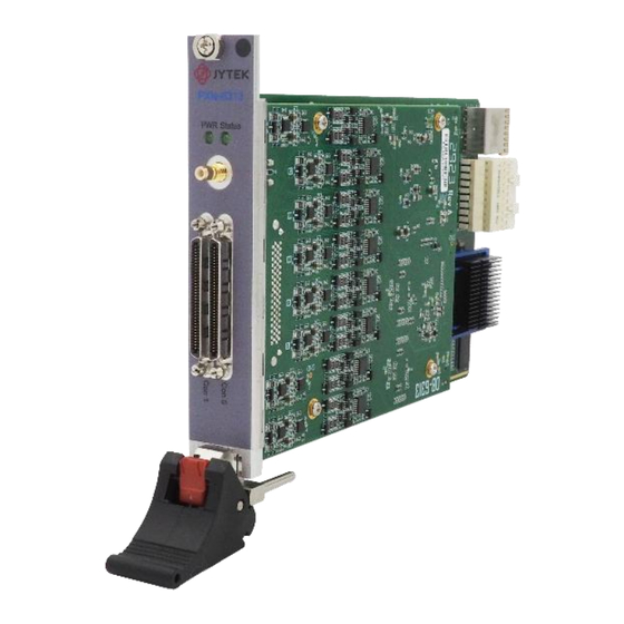
- Page 2 JY-6313 Specs and Manual_EN 1. JY-6313 Specifications Overview The JY-6313 is a high-density strain measurement module designed for precision applications, offering 16 channels and supporting quarter, half, and full bridge configurations. With five gain options and a 24-bit high-resolution ADC, it ensures accurate and customizable measurements.
- Page 3 Ratiometric Range (±mV/V) 6.25 400/V 12.5 200/V 100/V 50/V 25/V Table 2 Input Range *Vex:Bridge excitation voltage. 1.3.3 Fault Protection Powered On 30 V Powered Off 30 V EX +/- Short Table 3 Fault protection JY-6313 | jytek.com | 2...
- Page 4 … Stability 25 ppm/°C max … Calibration Factory calibrated *The bridge completion function provided by the terminal block TB-6313. If TB-6313 is not used, JY-6313 can only connect to the full-bridge input. Table 4 Bridge Completion Offset Nulling Type Hardware nulling Nulling Range …...
- Page 5 Input Gain Gain Error (% of Reading) Offset Error (uV/V) (Vex=5V) 6.25 ±80 mV/V 120/Vex 12.5 ±40 mV/V 80/Vex ±20 mV/V 80/Vex ±10 mV/V 80/Vex ±5 mV/V 80/Vex Table 8 24-hour Accuracy (23℃±1℃) *Vex:Bridge excitation voltage. JY-6313 | jytek.com | 4...
- Page 6 �� Table 11 Bandwidth and Alias Rejection (Operation Mode = Auto*) *Operation Mode:JY-6313 digital filters offer two modes, Normal and Low-Latency, each with different support sample rate ranges, group latency and passband bandwidth, and by default, the driver automatically selects according to the sample rate. See Chapter 7.3 for a more detailed description.
- Page 7 Start or reference trigger Rising-edge, Rising-edge with hysteresis, Falling-edge, Mode Falling-edge with hysteresis, Entering Window, Leaving Window Table 13 Analog Trigger Digital Trigger PFI0, Source PXI_TRIG<0..7>, PXI_STAR Purpose Start or reference trigger Polarity Software-selectable Table 14 Digital Trigger JY-6313 | jytek.com | 6...
- Page 8 2.6 V with IOH = 12 mA 0.15 V with IOL = -100 μA 0.7 V with IOL = -12 mA Output Range 0 V to 3.3 V Output Current ±50 mA Output Impedance 33 Ω Table 19 PFI Characteristics (Output) JY-6313 | jytek.com | 7...
- Page 9 0 °C to 50 °C Relative humidity range 10% to 90%, noncondensing Table 23 Operating Environment Storage Environment Ambient temperature range -40 °C to 71 °C Relative humidity range 5% to 95%, noncondensing Table 24 Storage Environment JY-6313 | jytek.com | 8...
- Page 10 16-ch, 80kS/s, 24-Bit, PXIe Strain/Bridge Input Module ⚫ Accessories: Cable: ACL-1016868-1 1M 68pin VHDC-SCSI twisted pair cable (PN: JY7996916-01) ACL-1016868-2 2M 68pin VHDCI-SCSI twisted pair cable (PN: JY7996916-02) Terminal Block: TB-6313: 8-ch for PCIe/PXIe-6313 (PN: JY8743398-01) RM-6313: 32-ch for PCIe/PXIe-6313(PN: JY9939593-01) JY-6313 | jytek.com | 9...
- Page 11 JY-6313 Specs and Manual_EN Table of Contents 1.JY-6313 Specifications ........................1 2.Order Information ........................... 9 3.Introduction ..........................14 4.Hardware Specifications ........................ 14 5.Software ............................21 6.Connecting Wheatstone Bridge ..................... 23 JY-6313 | jytek.com | 10...
- Page 12 JY-6313 Specs and Manual_EN 7.Operating JY-6313 ......................... 45 8.Calibration ............................ 67 9.Using JY-6313 in Other Software ....................67 JY-6313 | jytek.com | 11...
- Page 13 Table 32 Digital Filter Group Delay (Operation Mode = Normal)............47 Table 33 Digital Filter Group Delay (Operation Mode = LowLatency) ..........48 Table 34 Mircostrain range in different configurations ..............50 Figure 1 Full-Bridge Input and TB-6313/JY-6313 ................15 JY-6313 | jytek.com | 12...
- Page 14 Figure 6 Ideal and Actual Load Response on the Bridge ..............24 Figure 7 Voltage Drop Due to Lead Resistance .................. 25 Figure 8 Connecting Remote Sensing to JY-6313 ................25 Figure 9 Hardware Offset Nulling Process ..................26 Figure 10 Shunt Calibration Diagram ....................27 Figure 11 TB-6313 ..........................
- Page 15 Learn by Example is a unique feature in JYTEK product manual. in this manual. We provide many sample programs for this device. Open JYPEDIA and search for JY-6313 in the driver sheet, select JY6313_Examples.zip. This will lead you to download the sample program for this device.
- Page 16 This chapter provides the hardware specifications of JY-6313. System Diagram Figure 1 shows how JY-6313 is typically used to measure the voltage through bridge. A Wheatstone bridge sensor connects to JY-6313 in quarter-, half-, and full bridge configurations. Figure 1 Full-Bridge Input and TB-6313/JY-6313 The accuracy and resolution of the voltage measurement are determined by those Wheatstone bridge and strain-gage connected to JY-6313.
- Page 17 Front Panel Figure 2 JY-6313 Front Panel Pin Definition JY-6313 provides 16 channels of strain measurements and 1 digital input channel (for digital triggering).Blow Tables list the definitions of all pins on the front panel connectors. Pin Name Signal Description Positive differential analog input.
- Page 18 JY-6313 Specs and Manual_EN Table 26 Front Panel Pinout Definition JY-6313 | jytek.com | 17...
- Page 19 Positive excitation output. Negative excitation output. Negative remote sensing input QTR/SC The quarter-bridge connection point or shunt calibration connection point depends on the strain configuration. Do not use this pin. Table 27 TB-6313 RJ45 Pinout Definition JY-6313 | jytek.com | 18...
- Page 20 Ratiometric (mV/V) Measurement Accuracy The basic ratiometric measurement accuracy of JY-6313 is shown in Table 28. Ratiometric Range Input Gain Gain Error (% of Reading)
- Page 21 (% of Reading) (% of Reading) ±80 mV/V 6.25 0.1% 0.03% ±40 mV/V 12.5 0.1% 0.06% ±20 mV/V 0.1% 0.12% ±10 mV/V 0.1% 0.24% ±5 mV/V 0.1% 0.48% Table 29 Calculating Gain and Offset Errors JY-6313 | jytek.com | 20...
- Page 22 Microsoft Windows: Windows 7 32/64 bit, Windows 10 32/64 bit. Linux Kernel Versions: There are many Linux versions. It is not possible JYTEK can support and test our devices under all different Linux versions. JYTEK will at the best support the following Linux versions.
- Page 23 Once you get yourself familiar with how one JYTEK DAQ card works, you should be able to know how to use all other DAQ hardware by using the same methods.
- Page 24 This can be done by using an accurate voltage source or measuring the voltage. The JY-6313 module includes a high-precision, factory-calibrated excitation source capable of compensating for voltage drops in lead wires, ensuring that the bridge receives an excitation voltage very close to the target voltage.
- Page 25 However, resistance in lead wires can cause offset and gain errors, as illustrated in Figure 6. Figure 6 Ideal and Actual Load Response on the Bridge The JY-6313 module provides three methods to correct these errors: remote sensing, offset nulling, and shunt calibration. 6.2.1 Remote Sensing The resistance in the wires connecting the bridge to the excitation source can result in a voltage drop, as shown in Figure 7.
- Page 26 The JY-6313 module offers a Remote Sensing feature to correct errors introduced by excitation lead resistance. To utilize this, connect the remote sensing inputs of the JY-6313 as close to the bridge circuit as possible, as shown in the full-bridge diagram in Figure 8.
- Page 27 Ideally, the bridge output should be 0V with no load. However, resistance differences among bridge legs can produce a non-zero offset. The JY-6313 module compensates for offset errors using integrated voltage generators that provide both coarse and fine adjustments. The coarse offset ranges from -100mV to +100mV with a 1mV resolution, and after initial signal amplification (selectable between x4 to x64), a fine offset adjustment of -400mV to ±400mV, with approximately 38uV resolution, is applied before reaching the ADC.
- Page 28 Refer to Figure 16 for setup details. JY-6313’s shunt calibration includes a software-controlled switch and shunt calibration resistors on the TB-6313 blocks. Call JY6313AITask.PerformShuntCalibration() before data acquisition. The module automatically calculates a gain adjustment coefficient by measuring strain pre- and post-shunt, compensating for subsequent measurements.
- Page 29 JY-6313 Specs and Manual_EN Using Terminal Block TB-6313 TB-6313 is a dedicated terminal block for JY-6313, as shown in Figure 11. Each TB-6313 can provide 8 transducer channels, Ch0 to Ch7. Figure 11 TB-6313 TB-6313 provides three main functions: ◼...
- Page 30 Figure 13 The back of TB-6313 When connecting transducer to JY-6313 via TB-6313, you can first connect the transducer to the pins of an RJ45-to-8pins converter, and then connect the converter to the TB-6313 with an RJ45 cable, as shown in Figure 14.
- Page 31 When connecting a quarter-bridge or half-bridge, the TB-6313 is mandatory; when connecting a full- bridge, TB-6313 is optional. However, in either case, you need to inform JY-6313 whether the TB-6313 has been used, as the JY-6313 needs to know this information to determine whether to configure the terminal block.
- Page 32 A passive quarter-bridge completion resistor (R3) alongside half-bridge completion resistors (R1 and R2) from the TB-6313 block. Shunt calibration resistor (R_SC) and Shunt Cal switch from the JY-6313. Sensitivity: ~0.5μV/V per με, for GF = 2.0. Figure 16 Quarter-Bridge Type I Circuit Diagram Diagram symbols and equations: ...
- Page 33 Figure 17 Quarter-Bridge Type II Measuring Axial and Bending Strain Key features of Quarter-Bridge Type II: One active and one dummy gauge for temperature compensation. Half-bridge completion resistors in TB-6313. Sensitivity: ~0.5μV/V per με, for GF = 2.0. JY-6313 | jytek.com | 32...
- Page 34 GF—Gage Factor, specified by the gage manufacturer. ◼ —Measured voltage of the bridge. ◼ —Excitation voltage provided by the JY-6313. ◼ —10kΩ resistor in series with the Shunt Cal switch to protect against external fault voltages. Protect The total shunt cal resistance is equal to the R and R series combination.
- Page 35 Poisson gage and is mounted perpendicular to the principal axis of strain. Half-bridge completion resistors (R and R ) are provided by TB-6313. Sensitive to both axial and bending strain. Sensitivity ~ 0.65μV/V per με, for GF = 2.0. JY-6313 | jytek.com | 34...
- Page 36 Poisson’s ratio is a material property of the specimen you are measuring. —Measured voltage of the bridge. —Excitation voltage provided by JY-6313. —10kΩ resistor in series with the Shunt Cal switch to protect against external fault voltages. Protect...
- Page 37 Half-bridge completion resistors provided by the TB-6313. Sensitive to bending strain and rejects axial strain. Sensitivity ~ 1μV/V per με, for GF = 2.0. Figure 22 Half-Bridge Type II Circuit Diagram JY-6313 | jytek.com | 36...
- Page 38 GF—Gage Factor, specified by the gage manufacturer. —Measured voltage of the bridge. —Excitation voltage provided by JY-6313. —10kΩ resistor in series with the Shunt Cal switch to protect against external fault voltages. Protect The total shunt cal resistance is equal to the R and R series combination.
- Page 39 �� = ���� As shown in the circuit diagram, all signals of the bridge are directly connected to the JY-6313, and the TB-6313 only provides the SC resistor at this time. Therefore, you can choose to use TB-6313 or a general...
- Page 40 Four active strain gauges: two mounted in the direction of bending strain, and two Poisson gauges perpendicular to the strain axis. Rejects axial strain and measures bending strain with high sensitivity. Sensitivity ~ 1.3μV/V per με, for GF = 2.0. JY-6313 | jytek.com | 39...
- Page 41 Poisson’s ratio is a material property of the specimen you are measuring. —Measured voltage of the bridge. —Excitation voltage provided by JY-6313. —10kΩ resistor in series with the Shunt Cal switch to protect against external fault voltages. Protect...
- Page 42 A full-bridge type III configuration has the following characteristics: Contains four active strain gauges: two for measuring axial strain and two Poisson gauges transverse to the principal axis. Rejects bending strain. Sensitivity ~ 1.3μV/V per με, for GF = 2.0. JY-6313 | jytek.com | 41...
- Page 43 —Shunt calibration resistor located inside the TB-6313. —Measured voltage of the bridge. —Excitation voltage provided by JY-6313. —10kΩ resistor in series with the Shunt Cal switch to protect against external fault voltages. Protect The total shunt cal resistance is equal to the R and R series combination.
- Page 44 JY-6313 Specs and Manual_EN As shown in the circuit diagram, all signals of the bridge are directly connected to the JY-6313, and the TB-6313 only provides the SC resistor at this time. Therefore, you can choose to use TB-6313 or a general terminal block.
- Page 45 JY-6313 Specs and Manual_EN Figure 30 Full-Bridge with General Terminal Block Circuit Diagram To add a ratiometric measurement channel, do as shown in the code below: JY-6313 | jytek.com | 44...
- Page 46 After you have installed the driver software and the SeeSharpTools, you are ready to use Microsoft Visual Studio C# to operate the JY-6313 products. This chapter will take JY-6313 as an example for the introduction. If you are already familiar with Microsoft Visual Studio C#, the quickest way to use JY-6313 boards is to go through our extensive examples.
- Page 47 JY-6313 Specs and Manual_EN Learn by example 7.2. ◼ Connect the two bridges (Ch0 is full-bridge, Ch1 is quarter-bridge) to JY-6313 via TB-6313. ◼ Open Winform AI Continuous Multi-Channel, Enable Ch0 and Ch1 and set related parameters. This example program will continuously acquire from multiple channels.
- Page 48 JY-6313 Specs and Manual_EN 7.2.1 Continuous Acquisition An AI acquisition task will acquire the data continuously until the task is stopped. The JY-6313 device will continue acquiring data and save the data in a FIFO buffer. You specify how many samples to read back by the user buffer’s length, if your program does not read the data fast enough, the FIFO buffer...
- Page 49 Sample Rate Group Delay (Samples) 7.8125��/�� ≤ �� ≤ 62.5��/�� 0.82 �� 62.5��/�� < �� ≤ 4����/�� 0.88 �� Table 33 Digital Filter Group Delay (Operation Mode = LowLatency) Figure 33 Frequency Respond (OperationMode = LowLatency) JY-6313 | jytek.com | 48...
- Page 50 500S/s, otherwise, use Low-Latency mode. The group delays at different sample rates are shown in Table 12. Strain Measurement Range The JY-6313 offers a total of 5 input gain options: x6.25, x12.5, x25, x50, and x100. The measurable microstrain range under each gain option is also related to several factors, including: ◼...
- Page 51 As mentioned in Chapter 6.2, JY6313 provides offset nulling and shunt calibration functions for on-site bridge calibration after the measurement system has been set up. To ensure these bridge calibration functions work correctly, you need to follow these steps as shown in Figure 34 to operate JY6313: JY-6313 | jytek.com | 50...
- Page 52 Figure 34 Bridge calibration process 7.5.1 Perform Offset Nulling During the offset nulling process, JY-6313 will repeatedly measure the input voltage and adjust the output voltage of the internal offset voltage generator until the voltage input to the ADC is as close to 0V as possible, or until the output of the bias voltage generator reaches its maximum range.
- Page 53 In the process of shunt calibration, similar to the offset nulling process, JY-6313 measures the input voltage once when the SC switch is open and once when it is closed. JY-6313 compares the two measurement results to calculate a gain adjustment coefficient. Before the completion of the shunt calibration, it is essential to ensure that the external input is in a stable state.
- Page 54 JY-6313 Specs and Manual_EN Triger Source JY-6313 has 4 trigger types: Immediate trigger, Software trigger, Analog trigger, and Digital trigger. The trigger type is a property and set by driver software. Users can employ different triggering types to meet the measurement requirements under different working conditions 7.6.1 Immediate trigger...
- Page 55 Falling Slope Trigger. Rising Slope Trigger: The Edge comparator output is high when the signal goes above the threshold; the output is low when the signal goes below the threshold as shown in Figure 37. JY-6313 | jytek.com | 54...
- Page 56 Hysteresis with Falling Slope Trigger: The Hysteresis comparator output is high when the signal must first be above the high threshold, then goes below the low threshold. The output will change to low when the signal goes above the high threshold as shown in Figure 40. JY-6313 | jytek.com | 55...
- Page 57 Leaving Window Trigger: The window comparator output is high when the signal leaves the window defined by the Low Threshold and High Threshold. The output will change to low when the signal enters the window as shown in Figure 42. JY-6313 | jytek.com | 56...
- Page 58 Figure 41 Entering Window Trigger Figure 42 Leaving Window Trigger Learn by example 7.6.3 ◼ Connect a full-bridge of strain gages to JY-6313 Ch0. ◼ Open Winform AI Finite Analog Trigger, set the following numbers as shown. JY-6313 | jytek.com | 57...
- Page 59 The edge of EdgeComparator set by Anlg Trig Edge. (Rising and Falling). Set it to Rising. ➢ Trigger source can be any channel of JY-6313 analog input. Set it to Channel_0. ➢ According to the rules of Rising mentioned above, the signal acquisition will not start until it raises to 100����, which is set by Threshold above.
- Page 60 Figure 45 External Digital Trigger Learn by Example 7.6.4 ◼ Connect a bridge to JY-6313 Ch0 via TB-6313, and a pulse generator to Ext_Trig through SMB cables. ◼ Set square wave signal (f=1k, Vpp =5V, Duty = 5%) for Ext_Trig.
- Page 61 Trigger Mode The JY-6313's analog inputs support several trigger modes: start trigger, reference trigger, and re-trigger. 7.7.1 Start Trigger In this mode, data acquisition begins immediately after the trigger. This trigger mode is suitable for continuous acquisition and finite acquisition.
- Page 62 ⚫ Total samples: 1000. ⚫ Channel Count: 1 ⚫ Pre-trigger samples: 10. ⚫ After triggering, it returns a total of 1000 samples, 10 being pre-triggered, 990 after triggering The principle is shown in Figure 48. JY-6313 | jytek.com | 61...
- Page 63 Figure 48 Reference Trigger 7.7.3 Retrigger JY-6313 series products support retrigger mode. In the retrigger mode, you can set the number of retrigger and the length of each acquisition. Assuming that the number of re triggers is n and the length of each trigger acquisition is m, the length of all acquisition data is n * m * channel count.
- Page 64 Figure 50 Multi-device Sync Topology Learn by Example 7.8 ◼ Connect the same signal source to JY-6313(PXIe chassis Slot 0) Ch0 and JY-6313(PXIe chassis Slot1) Ch0 using cables of same length. ◼ To verify the synchronization accuracy, a signal source generated a 700mVpp, 1kHz sine wave signal (with a common-mode voltage of 1.5V) to simulate the bridge output.
- Page 65 After clicking the Commit button, the Slave device and the Master device will execute the JY6313AITask.Commit() method in sequence. The driver will automatically complete the reference clock locking and other parameter configurations, then the Master device will send a sync pulse to JY-6313 | jytek.com | 64...
- Page 66 Master device will send a trigger signal to the Slave device. Following this, all devices will begin data acquisition at the same moment, as shown in Figure 55. JY-6313 | jytek.com | 65...
- Page 67 JY-6313 Specs and Manual_EN Figure 55 Master sends trigger to slave The acquisition results (ratiometric value in mV/V) is shown in the figure below. Figure 56 Synchronous acquisition results JY-6313 | jytek.com | 66...
- Page 68 JYTEK provides and supports a native python driver for JY-6313 cards. There are many different versions of Python. JYTEK has only tested in CPython version 3.5. There is no guarantee that JYTEK python drivers will work correctly with other versions of Python.
- Page 69 JYTEK Warranty and Support Services With our complete software and hardware products, JYTEK is able to provide technical and sales services to wide range of applications and customers. In most cases, our products are backed by a 1-year warranty.
- Page 70 JY-6313 Specs and Manual_EN 11. Statement The hardware and software products described in this manual are provided by JYTEK China, or JYTEK in short. This manual provides the product review, quick start, some driver interface explanation for JYTEK JY- 6313 Series family of multi-function data acquisition boards. The manual is copyrighted by JYTEK.
Need help?
Do you have a question about the JY-6313 and is the answer not in the manual?
Questions and answers