
Related Manuals for JYTEK PXI-67931


Summary of Contents for JYTEK PXI-67931
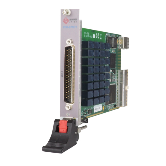
- Page 1 PXI-67931 4x8 2-Wire Matrix Module User’s Manual Manual Rev.: Rev. 1.1 Date: Mar 8, 2022...
- Page 2 Copyright © 2004, 2022 JYTEK Technology Inc. All Rights Reserved. Revision History. 1.00 09-07-2004 Initial release 08-03-2022 Remove Star Trigger Out functionality Disclaimer The information in this document is subject to change without prior notice in order to improve reliability, design, and function and does not represent a commitment on the part of the manufacturer.
- Page 3 European Union's Restriction of Hazardous Substances (RoHS) directive and Waste Electrical and Electronic Equipment (WEEE) directive. Environmental protection is a top priority for JYTEK. We have enforced measures to ensure that our products, manufacturing processes, components, and raw materials have as little impact on the environment as possible.
- Page 4 Getting Service Customer satisfaction is our top priority. Contact us should you require any service or assistance. SHANGHAI JYTEK CO.,LTD. Web Site http://www.jytek.com Sales & Service service@jytek.com Telephone No. +86-21-50475899 Fax No. +86-21-50475899 Mailing Address 300 Fang chun Rd., Zhangjiang Hi-Tech Park,...
-
Page 5: Table Of Contents
2.4 Installing the switch module into a PXI Platform ....6 Chapter 3 Signal Connection ............9 3.1 PXI-67931 Topology ............. 9 3.2 PXI-67931 Pin assignment & Description ......10 3.3 TB-6231 Terminal Board ............. 11 Chapter 4 Operation Theorem ..........21 4.1 Hardware Block Diagram ........... -
Page 6: How To Use This Manual
How to Use This Manual This User Manual is designed to assist users in the installation of the JYTEK PXI-67931, 4x8 2-Wire Matrix PXI Switch module. Chapter 1 Introduction Gives an outline and overview of JYTEK switch modules’ features, specifications, and applications. -
Page 7: Chapter 1 Introduction
Introduction JYTEK PXI-67931 is a matrix module with 32 cross-point 2-wire relays (DPDT, 2 Form C). The default configuration of the PXI-67931 is a 4-group 2x4 2-wire matrix. With the termination board, TB-6231, users can flexibly choose one of the configurations: one 4x8, two 4x4, one 2x16, two 2x8, and four 2x4. -
Page 8: Applications
1.2 Applications Industrial ON/OFF control • External high power relay driving and signal switching • • Laboratory automation Industrial automation • • Switch contact status sensing Limit switch monitoring • Cooperating with other modules such as A/D and D/A peripherals to •... -
Page 9: Software Support
• 160 mm x 100 mm 1.4 Software Support JYTEK‘s ADL-SWITCH driver package is for Microsoft Windows operating systems, including Windows 98/ME/NT/2000/XP. The driver package also provides utilities to test your switch module, as well as programming samples and source codes in Microsoft Visual Basic and Visual C/C++. - Page 10 This page intentionally left blank. 4 • Introduction...
-
Page 11: Chapter 2 Installation
• ADL-Switch User’s Guide If any of these items are missing or broken, please do not hesitate to contact JYTEK or the dealer from whom the product was purchased. Keep the shipping materials and carton for future storage or shipping. -
Page 12: Mechanical Drawing
2.4 Installing the switch module into a PXI Platform To insert the JYTEK PXI switch module, align the module’s edge with the card guide in the PXI chassis. Slide the switch module into the chassis, until resistance is felt from the PXI connector. - Page 13 Figure 2: Installing the switch module into a PXI platform Installation • 7...
- Page 14 This page intentionally left blank. 8 • Installation...
-
Page 15: Chapter 3 Signal Connection
This configuration can let user simultaneous connects one or more input signals to one or more devices. All signal paths on PXI-67931 are inherently break-before-make. -
Page 16: Pxi-67931 Pin Assignment & Description
3.2 PXI-67931 Pin assignment & Description 22. C8+ 43. C0+ 23. C8- 1. R0+ 44. C0- 24. C9+ 2. R0- 45. C1+ 25. C9- 3. R1+ 46. C1- 26. C10+ 4. R1- 47. C2+ 27. C10- 5. R2+ 48. C2- 28. -
Page 17: Tb-6231 Terminal Board
Configurations The TB-6231 is a screw terminal board with D-sub 62-pin female connector. The terminal board can attach to PXI-67931 directly, or through JYTEK‘s custom- made high-capacity 62-pin D-sub cable. Users can use the TB-6231 terminal board to make various matrix configurations. - Page 18 Figure 4: 2x4 Matrix (I) In this configuration, the TB-6231 would not have any shorted pads. The grid below shows the names used for software configuration with corresponding traces to the TB-6231. 12 • Signal Connection...
- Page 19 Figure 5: 2x4 Matrix (II) Signal Connection • 13...
- Page 20 This configuration has two independent 2x8 matrices ranging from Bank0 to Bank1, each has two rows and eight columns. The following diagram illustrates the PXI-67931 with the TB-6231 to produce relative paths. Figure 6: 2x8 Matrix (I) To use a 2x8 matrix, short the following TB-6231 pads.
- Page 21 Figure 7: 2x8 Matrix (II) 2x16 Matrix This configuration has one independent 2x16 matrix with two rows and 16 columns. The following diagram illustrates the PXI-67931 with the TB-6231 to produce relative paths Signal Connection • 15...
- Page 22 Figure 8: 2x16 Matrix (I) To use a 2x16 matrix, short the following eight TB-6231 pads. The grid below shows the names used for software configuration with corresponding traces to the TB-6231 Figure 9: 2x16 Matrix (II) 16 • Signal Connection...
- Page 23 This configuration has two independent 4x4 matrices ranging from Bank0 to Bank1, each with four rows and four columns. The following diagram illustrates the PXI-67931 with the TB-6231 to produce relative paths Figure 10: 4x4 Matrix (I) To use a 2x16 matrix, short the following 16 TB-6231 pads.
- Page 24 Figure 11: 4x4 Matrix (II) 4x8 Matrix This configuration has one 4x8 matrix, Bank0, with four rows and eight columns. The following diagram illustrates the PXI-67931 with the TB-6231 to produce relative paths 18 • Signal Connection...
- Page 25 Figure 12: 4x8 Matrix (I) To use a 2x16 matrix, short the following 24 TB-6231 pads. The grid below shows the names used for software configuration with corresponding traces to the TB-6231 Signal Connection • 19...
- Page 26 Figure 13: 4x8 Matrix (II) 20 • Signal Connection...
-
Page 27: Chapter 4 Operation Theorem
Operation Theorem 4.1 Hardware Block Diagram The JYTEK PXI Switch Module features an onboard FPGA for relay switching control, trigger control, scanlist storage and sequencing. The PXI triggering and synchronization functions, such as Star Trigger and Trigger Bus are also supported. In addition... -
Page 28: Operation Mode
Trigger In The Trigger In signal from PXI instruments or external measurement devices instruct the JYTEK PXI switch module to update the relay pattern according to the one specified in the scanlist entry. Users may specify wait-for-trigger instruction in a scanlist entry, to have the switch module wait for the Trigger In before relay pattern is updated. - Page 29 Figure 15 illustrates the available signal sources for the Trigger In signal. Signal names in the solid-line box represent the external (physical) signal on connectors, and signals in the dotted-line box represents switch module’s internal signal. Software Trigger TRG_IN Trigger In Signal Trigger Bus [7…0] AUX[7…0] Star Trigger In...
- Page 30 Handshaking protocol Figures 17 and 18 depict the relationship between Trigger In, Scanner Advanced, and relay pattern in handshaking mode. In Figure 17 the Scanner Advanced is set to pulsating mode. Trigger In Scanner Advanced Pattern #2 Pattern #3 attern Relay status Operation start Figure 17: Handshaking operation (Scanner Advanced set in pulsating mode)
- Page 31 5ms for PXI-67931. T the user specified scan delay time in the scanlist entry, indicating the time...
- Page 32 Trig In to TRG_IN on terminal board, and the VM Comp to S_ADV. Follow the instructions below to ensure the handshake functions properly: Configure JYTEK PXI switch module’s Trigger In to rising-edge triggered, Scanner Advanced output in active-low pulsating mode with pulse width of at least 2us.
- Page 33 PXI instruments, and/or simplify field wiring across multiple JYTEK Switch Modules. On JYTEK Switch Modules, the trigger bus driver is disconnected from PXI trigger bus before users’ configuration. Figure 20 illustrates the available signal destinations for Trigger Bus[7..0]. Signal names in the solid-line boxes represent the external (physical) signals on connectors while signals in the dotted-line boxes represent the switch module’s internal signal.
-
Page 34: Trigger Bus
Software Trigger Trigger In Signal Scanner Adv. Signal AUX [3…2] Trigger Bus[7..0] Star Trigger In WDT Overflow SHDNn Figure 20: Available signal sources for Trigger Bus[7..0] 28 • Operation Theorem... -
Page 35: Auxiliary Digital I/O
4.5 Auxiliary Digital I/O The eight auxiliary digital I/O lines on JYTEK Switch Modules provide versatility to users’ control applications. Each digital I/O line can be input, output or tri-stated. When in output mode, users can still read back the actual logic- level on the I/O line. -
Page 36: Hot-Swap
Note: Microsoft Windows 2000 does not natively support hot-swap however, PXI-67931 can be hot-swapped by manual control via an additional hot-swap driver. For the hot-swap driver on Windows 2000 and other operating systems such as Linux, VxWorks, etc., please contact JYTEK for more information. -
Page 37: Watchdog Timer
Star Trigger In Figure 23: Available trigger sources for emergency shutdown The default relay pattern for emergency shutdown is All-Off on PXI-67931; users can change the pattern by Windows API. Upon receiving the emergency shutdown trigger, the Switch Module enters shutdown mode, and the relay pattern is switched to the preset state. - Page 38 Int. WDTimer WDT Overflow Trigger Bus Star Trigger In Figure 24:.Available trigger sources for watchdog timer overflow The watchdog timer overflow interval can be programmed through Windows API. After enabling the watchdog timer, users must periodically reset the timer by software command.
-
Page 39: Warranty Policy
Warranty Policy Thank you for choosing JYTEK. To understand your rights and enjoy all the after- sales services we offer, please read the following carefully: Before using JYTEK‘s products please read the user manual and follow the instructions exactly. When sending in damaged products for repair, please attach an RMA application form.
Need help?
Do you have a question about the PXI-67931 and is the answer not in the manual?
Questions and answers