
Related Manuals for JYTEK PXI-67921


Summary of Contents for JYTEK PXI-67921
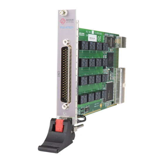
- Page 1 PXI-67921 24-ch, Multiplexer DPDT Relay Module User’s Manual Manual Rev.: Rev. 1.0 Date: February 8, 2020...
- Page 2 Trademarks NuDAQ™, NuIPC™, NuDAM™, NuPRO™ are registered trademarks of JYTEK Technology Inc. Other product names mentioned herein are used for identification purposes only and may be trademarks and/or registered trademarks of their respective companies.
- Page 3 Environmental Responsibility JYTEK is committed to fulfill its social responsibility to global environmental preservation through compliance with the European Union's Restriction of Hazardous Substances (RoHS) directive and Waste Electrical and Electronic Equipment (WEEE) directive. Environmental protection is a top priority for JYTEK. We...
- Page 4 Getting Service Customer satisfaction is our top priority. Contact us should you require any service or assistance. Shanghai Jianyi Technology Co., Ltd. www.jytek.com Website Service Telephone No. +86-21-50475899 Fax No. Mailing +86-21-50475899 Address Room 201, Building 3, NO.300 Fangchun Road, Shanghai...
-
Page 5: Table Of Contents
2.3 Installing the switch module into a PXI Platform ....6 Chapter 3 Signal Connection ............ 9 3.1 PXI-67921 Topology ............9 3.2 PXI-67921 Pin Assignments & Descriptions ....10 3.3 TB-6221 Terminal Board ..........13 2-wire MUX ................ 14 2-wire, 2-group MUX ............ -
Page 6: How To Use This Manual
How to Use This Manual This User Manual is designed to assist users in the installation of the JYTEK PXI-67921, 24-ch Multiplexer DPDT Relay PXI Switch module. Chapter 1 Introduction Gives an outline and overview of JYTEK switch modules’ features, specifications, and applications. -
Page 7: Chapter 1 Introduction
Introduction JYTEK PXI-67921 is a relay multiplexer module which consists of 24 2-wire relays (DPDT, 2 Form C). PXI-67921 provides 48x1 1-wire and 24x1 2-wire and 12x1 4-wire configurations and typically connects one instrument, such as a DMM, a digitizer or a signal source, with many points which need measurement or excitation. -
Page 8: Applications
1.2 Applications Industrial ON/OFF control • External high power relay driving and signal switching • Laboratory automation • Industrial automation • Switch contact status sensing • • Limit switch monitoring Cooperating with other modules such as A/D and D/A peripherals to •... -
Page 9: Software Support
Windows 98/ME/NT/2000/XP. The driver package also provides utilities to test your switch module, as well as programming samples and source codes in Microsoft Visual Basic and Visual C/C++. For other operating systems, please contact JYTEK for more information. Introduction • 3... - Page 10 This page intentionally left blank. Introduction •...
-
Page 11: Chapter 2 Installation
Installation This chapter describes the installation process for the JYTEK switch module. Please read the contents of the package and the disassembling information carefully as they are important in the implementation of the JYTEK switch module. 2.1 Contents The package consists of the following items in addition to the User Manual: PXI-67921, 24-ch Multiplexer DPDT Relay •... -
Page 12: Mechanical Drawing
2.4 Installing the switch module into a PXI Platform To insert the JYTEK PXI switch module, align the module’s edge with the card guide in the PXI chassis. Slide the switch module into the chassis, until resistance is felt from the PXI connector. Push the ejector upwards and fully Installation •... - Page 13 insert the switch module into the chassis. Once inserted, a “click” can be heard from the ejector latch. Tighten the screws on the front panel. Figure 2: Installing the switch module into a PXI platform Installation •...
- Page 14 This page intentionally left blank. 8 • Installation...
-
Page 15: Chapter 3 Signal Connection
48×1 1-wire multiplexer, or one group of 12×1 4-wire multiplexer. These configurations are totally software programmable. The PXI-67921 typically connects one instrument, such as a DMM or digitizer, to many measurement points or a signal source to several points needing excitation. -
Page 16: Pxi-67921 Pin Assignments & Descriptions
3.2 PXI-67921 Pin Assignments & Descriptions 22. +5 V 43. COM2+ 23. CH8+ 1. CH0+ 44. COM2- 24. CH8- 2. CH0- 45. COM3+ 25. CH9+ 3. CH1+ 46. COM3- 26. CH9- 4. CH1- 47. CH18+ 27. CH10+ 5. CH2+ 48. CH18- 28. - Page 17 22. +5 VOUT 43. COM2+* 23. CH8 1. CH0 44. COM2-* 24. CH32 2. CH24 45. COM3+* 25. CH9 3. CH1 46. COM3-* 26. CH33 4. CH25 47. CH18 27. CH10 5. CH2 48. CH42 28. CH34 6. CH26 49. CH19 29.
- Page 18 Signal Name Type Description Input/Output Common---The common for each COM0± (one wire) bank. COM<0..3>± (two wire) COM<0..1>A±(four wire) COM<0..1>B± (four wire) Input/Output CH<0..47> (one wire) Channels---Where signals are CH<0..23>± (two wire) connected to the switch card. CHχ+ CH<0..11>A± (four wire) and CHχ- are switched together.
-
Page 19: Tb-6221 Terminal Board
Users can use the TB-6221 terminal board that consists of a printed circuit with screw terminals. The terminal block connects directly to the front panel I/O connector of the PXI-67921. The TB-6221’s default printed circuit is in 2-wire mode. If other configuration is preferred, user can refer the table on TB-6221 to identify the pin connected. -
Page 20: 2-Wire Mux
2-wire MUX This configuration has one 24x1 2-wire multiplexer Bank0, which has twenty- four channels. The following diagram illustrates the terminal board pin definition. Figure 3: 24x1 MUX Signal Connection •... -
Page 21: 2-Wire, 2-Group Mux
2-wire, 2-group MUX This configuration has two 12x1 2-wire multiplexers Bank0 and Bank1, each has twelve channels. The following diagram illustrates the terminal board pin definition. Figure 4: Two 12x1 MUX Signal Connection •... -
Page 22: 2-Wire, 4-Group Mux
2-wire, 4-group MUX This configuration has four 6x1 2-wire multiplexers Bank0, Bank1, Bank2 and Bank3, each has six channels. The following diagram illustrates the terminal board pin definition. Figure 5: Four 6x1 MUX Signal Connection •... -
Page 23: 1-Wire Mux
1-wire MUX This configuration has one 48x1 1-wire multiplexer Bank0, which has forty- eight channels. The following diagram illustrates the terminal board pin definition. Figure 6: 48x1 MUX Signal Connection •... -
Page 24: 4-Wire Mux
wire MUX This configuration has one 12x1 4-wire multiplexer Bank0, which has twelve channels. The following diagram illustrates the terminal board pin definition. Figure 6: 4-wire MUX Signal Connection •... -
Page 25: Chapter 4 Operation Theorem
Operation Theorem 4.1 Hardware Block Diagram The JYTEK PXI Switch Module features an onboard FPGA for relay switching control, trigger control, scanlist storage and sequencing. The PXI triggering and synchronization functions, such as Star Trigger and Trigger Bus are also supported. -
Page 26: Operation Mode
If relay contact bouncing is of a concern, users would need to insert software delay. JYTEK recommends the debounce time to be at least 5ms on PXI-67921. Auto-scan The JYTEK PXI switch module features onboard memory to store user specified scanlist of up to 1024-entry. - Page 27 connectors, and signals in the dotted-line box represents switch module’s internal signal. Software Trigger TRG_IN Trigger In Signal Trigger Bus [7…0] AUX[2…0] Star Trigger In Figure 8: Available signal sources for Trigger In Scanner Advanced After updating the relay pattern, the switch module starts its debounce timer and waits for the relay contacts to settle.
- Page 28 Handshaking protocol Figures 10 and 11 depict the relationship between Trigger In, Scanner Advanced, and relay pattern in handshaking mode. In Figure 11 the Scanner Advanced is set to pulsating mode. Trigger In Scanner Advanced Pattern #3 attern Pattern #2 Relay status Operation start Figure 10: Handshaking operation (Scanner Advanced set in pulsating mode)
- Page 29 5ms for PXI-67921. is the user specified scan delay time in the scanlist entry, indicating the time between the relay being debounced and the exact moment that a measurement device takes a new measurement.
- Page 30 Trig In to TRG_IN on terminal board, and the VM Comp to S_ADV. Follow the instructions below to ensure the handshake functions properly: Configure JYTEK PXI switch module’s Trigger In to rising-edge. triggered, Scanner Advanced output in active-low pulsating mode with pulse width of at least 2us.
-
Page 31: Trigger Bus
PXI instruments, and/or simplify field wiring across multiple JYTEK Switch Modules. On JYTEK Switch Modules, the trigger bus driver is disconnected from PXI trigger bus before users’ configuration. Figure 13 illustrates the available signal destinations for Trigger Bus[7..0]. - Page 32 Software Trigger Trigger In Signal Scanner Adv. Signal Trigger Bus[7..0] AUX [3…2] Star Trigger In WDT Overflow SHDNn Figure 13: Available signal sources for Trigger Bus[7..0] 26 • Operation Theorem...
-
Page 33: Auxiliary Digital I/O
4.5 Auxiliary Digital I/O The eight auxiliary digital I/O lines on JYTEK Switch Modules provide versatility to users’ control applications. Each digital I/O line can be input, output or tri-stated. When in output mode, users can still read back the actual logic- level on the I/O line. -
Page 34: Hot-Swap
Note: Microsoft Windows 2000 does not natively support hot-swap however, PXI-67921 can be hot-swapped by manual control via an additional hot- swap driver. For the hot-swap driver on Windows 2000 and other operating systems such as Linux, VxWorks, etc., please contact JYTEK for more information. -
Page 35: Watchdog Timer
Star Trigger In Figure 12: Available trigger sources for emergency shutdown The default relay pattern for emergency shutdown is All-Off on PXI-67921; users can change the pattern by Windows API. Upon receiving the emergency shutdown trigger, the Switch Module enters shutdown mode, and the relay pattern is switched to the preset state. - Page 36 Int. WDTimer WDT Overflow Trigger Bus Star Trigger In Figure 13:.Available trigger sources for watchdog timer overflow The watchdog timer overflow interval can be programmed through Windows API. After enabling the watchdog timer, users must periodically reset the timer by software command.
-
Page 37: Warranty Policy
Warranty Policy Thank you for choosing JYTEK. To understand your rights and enjoy all the after-sales services we offer, please read the following carefully: 1. Before using JYTEK's products please read the user manual and follow the instructions exactly. 2. All JYTEK products come with a two-year guarantee, repaired free of charge.
Need help?
Do you have a question about the PXI-67921 and is the answer not in the manual?
Questions and answers