
Related Manuals for JYTEK PCIe-5211

Summary of Contents for JYTEK PCIe-5211
- Page 1 PCIe/PXIe-5211 Timer/Counter Board User Manual User Manual Version: V1.0 Revision Date: Apr.7, 2020...
-
Page 2: Table Of Contents
3.2 System Software ................10 3.3 C# Programming Language .............. 10 3.4 PCIe/PXIe-5211 Series Hardware Driver .......... 10 3.5 Install the SeeSharpTools from JYTEK ..........11 3.6 Running C# Programs in Linux ............11 4. Operating PCIe/PXIe-5211 ..............12 4.1 Quick Start ..................12 4.2 Digital I/O Operations ................ - Page 3 6.3 LabVIEW ................... 36 7. About JYTEK ..................37 7.1 JYTEK China ..................37 7.2 JYTEK Korea and JYTEK In Other Countries ........37 7.3 JYTEK Hardware Products ............... 37 7.4 JYTEK Software Platform ..............38 7.5 JYTEK Warranty and Support Services ..........38 8.
- Page 4 Table 2-1 Basic ..................2 Table 2-2 DIO ................... 3 Table 2-3 PFI .................... 3 Table 2-4 Recommended Operating Conditions ........3 Table 2-5 Electrical ................... 3 Table 2-6 Basic ..................4 Table 2-7 Maximum Frequency of the Source .......... 4 Table 2-8 Minimum Pulse Measurement ..........
-
Page 5: Overview
The device utilizes a high-throughput PCI Express bus and multi-core optimized drivers and application software to provide high-performance capabilities. Please check with JYTEK for the latest 5211 series offering. 1.2 Main Features 8ch counter ... -
Page 6: Hardware Specifications
It is mainly composed of one DIO module and eight Timer/Counter modules, providing digital input, digital output, counter input, counter output functions. JYTEK's FPGA-based driver FirmDrive provides a stable and efficient PCIe / PXIe / USB interface. 2.2 Digital IO Specifications... - Page 7 8 mA(UserVcc=2.5 V) Output Low current (I 24 mA(UserVcc=3.3 V) 32 mA(UserVcc=5 V) Table 2-4 Recommended Operating Conditions Electrical Maximum input current of low-level voltage -2 µ A Maximum current of high-level voltage 2 µ A Table 2-5 Electrical PCIe/PXIe-5211 | jytek.com...
-
Page 8: Counter/Timer Specifications
Output applications Buffered Pulse Sequence Generation 200 MHz, Internal timebase 5 MHz, 100 kHz Internal timebase accuracy 2 ppm External timebase 0-50 MHz Gate Source Counter input A, B, Z Up_Down Sample Clock Table 2-9 Other Functions PCIe/PXIe-5211 | jytek.com... -
Page 9: Other Specifications
Bus and Power x8 PXIe peripheral module PXIe standard Specification V1.0 compliant Bus interface x1 and x4 PXI Express hybrid slot supported slots >=15 min Recommended warm-up time Calibration One year Recommended calibration interval Table 2-13 Bus and Power PCIe/PXIe-5211 | jytek.com... - Page 10 Physical Size and Environment 3 U PXIe External physical size Size Weight Indoor only Environment 0-55 ℃ Operating temperature Table 2-14 Physical Size and Enviroment PCIe/PXIe-5211 | jytek.com...
-
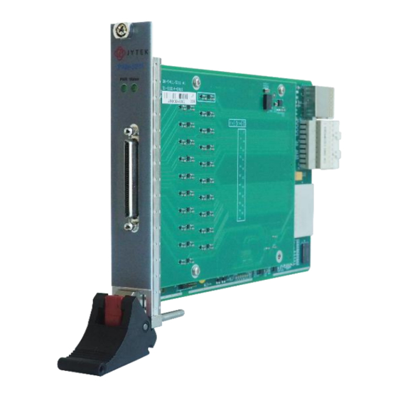
Page 11: Front Panel And Pin Definition
2.5 Front Panel and Pin Definition Figure 2-2 Front Pannel PCIe/PXIe-5211 | jytek.com... - Page 12 PFI25 PFI32 PFI22 PFI23 PFI20 PFI21 PFI18 PFI19 PFI16 PFI17 PFI14 PFI15 PFI33 PFI12 PFI13 PFI10 PFI11 PFI8 PFI9 PFI6 PFI7 PFI35 PFI34 PFI4 PFI5 PFI2 PFI3 PFI37 PFI36 PFI0 PFI1 PFI39 PFI38 Table 2-15 Pin Defination PCIe/PXIe-5211 | jytek.com...
-
Page 13: Default Routing For Counter Input/Output Signals
PFI8 PFI12 PFI16 PFI20 PFI24 PFI28 Two-Pulse Encoder B Input PFI2 PFI6 PFI10 PFI14 PFI18 PFI22 PFI26 PFI30 Pulse Generation Signal to Output PFI3 PFI7 PFI11 PFI15 PFI19 PFI23 PFI27 PFI31 Table 2-16 Counter Input Default Routing PCIe/PXIe-5211 | jytek.com... -
Page 14: Software
PCIe/PXIe-5211 boards can be used in a Windows or a Linux operating system. Microsoft Windows: Windows 7 32/64 bit, Windows 10 32/64 bit. Linux Kernel Versions: There are many Linux versions. It is not possible JYTEK can support and test our devices under all different Linux versions. JYTEK will at the best support the following Linux versions. -
Page 15: Install The Seesharptools From Jytek
Once you get yourself familiar with how one JYTEK DAQ card works, you should be able to know how to use all other DAQ hardware by using the same methods. -
Page 16: Operating Pcie/Pxie-5211
This chapter provides the operation guides for PCIe/PXIe-5211, including AI, AO, DI, DO, Timer and programmable I/O interface, etc. JYTEK provides extensive examples, on-line help and documentation to assist you to operate the PCIe/PXIe-5211 board. JYTEK strongly recommends you go through these examples before writing his own application. In many cases, an example can also be a good starting point for a user application. -
Page 17: Edge Counting
The count value is written to the register on each rising edge of the signal to measure as shown in Figure 4-2 Figure 4-2 Simple Edge Counting in Single Mode To configure the counter to work in this mode, set JY5211CITask.Mode to CIMode.Single. PCIe/PXIe-5211 | jytek.com | 13... - Page 18 The count value is stored into the buffer on each rising edge of the signal to measure as shown in Figure 4-4 Figure 4-4 Simple Edge Counting with Implicit SampleClk To configure the counter to work in this mode, set JY5211CITask.Mode to CIMode.Finite CIMode.Continuous, JY5211CITask.SampleClock.Source to CISampleClockSource.Implicit. PCIe/PXIe-5211 | jytek.com | 14...
- Page 19 Figure 4-6 Figure 4-6 Count Direction To cofigure the count direction, use the properties as belows: JY5211CITask.EdgeCounting.Direction – To specify count up, count down, or controled by an external signal. PCIe/PXIe-5211 | jytek.com | 15...
-
Page 20: Pulse Measurement
2) Finite/Continuous Mode with Explicit Sample Clock The count value of the duration of the high or low level is stored into the buffer on each rising edge of the sample clock, as shown in Figure 4-8 PCIe/PXIe-5211 | jytek.com | 16... - Page 21 Figure 4-9. Figure 4-9 Pulse Measurement with Implicit SampleClk To configure the counter to work in this mode, set JY5211CITask.Mode to CIMode.Finite CIMode.Continuous, JY5211CITask.SampleClock.Source to CISampleClockSource.Implicit. PCIe/PXIe-5211 | jytek.com | 17...
-
Page 22: Frequency Measurement
(��1) of the signal to measure, and the number of rising edges of timebase (��2) during those full periods. These two values are stored into the buffer on each rising edge of the sample clock, as shown in Figure 4-10. PCIe/PXIe-5211 | jytek.com | 18... - Page 23 To configure the counter to work in this mode, set JY5211CITask.Mode to CIMode.Finite CIMode.Continuous, JY5211CITask.SampleClock.Source to CISampleClockSource.Implicit. Timebase By default, the counter uses the onboard 200MHz timebase to measure pulses. Use the property JY5211CITask.FrequencyMeas.Timebase to configure the timebase. PCIe/PXIe-5211 | jytek.com | 19...
-
Page 24: Period Measurement
The number of rising edges of timebase between previous rising edge of the second signal and current rising edge of the first signal is written to the resgiter on each rising edge of the first signal. As shown in Figure 4-11. PCIe/PXIe-5211 | jytek.com | 20... - Page 25 Figure 4-12. Figure 4-12 Two-Edge Seperation with Explicit Sample Clock To configure the counter to work in this mode, set JY5211CITask.Mode to CIMode.Finite CIMode.Continuous, PCIe/PXIe-5211 | jytek.com | 21...
- Page 26 Please refer to chapter 4.5.3 for more information about timebase. Terminals To change the terminal of signals instead of using its default value shown in chapter 2.6, use following properties: JY5211CITask.TwoEdgeSeparation.FirstInputTerminal – First signal-to- measure input terminal. PCIe/PXIe-5211 | jytek.com | 22...
-
Page 27: Quadrature Encoder
When A leads B, the count increase occurs on the rising edge and the falling edge of A; when B leads A, the count reduction occurs on the rising edge and falling edge of A as shown inFigure 4-15. Figure 4-15 Quadrature Encoder x2 Mode PCIe/PXIe-5211 | jytek.com | 23... - Page 28 To configure the counter to work in this mode, set JY5211CITask.Mode to CIMode.Single. 2) Finite/Continuous Mode with Explicit Sample Clock The count value is stored into the buffer on each rising edge of the sample clock, as shown in Figure 4-17. PCIe/PXIe-5211 | jytek.com | 24...
-
Page 29: Two-Pulse Encoder
JY5211CITask.QuadEncoder.BInputTerminal – Signal B input terminal. 4.3.7 Two-Pulse Encoder The count value increases on the rising edge of A and decreases on the rising edge of B. Set JY5211CITask.Type to CIType.TwoPulseEncoder to use this function PCIe/PXIe-5211 | jytek.com | 25... - Page 30 The count value is stored into the buffer on each rising edge of the sample clock, as shown in Figure 4-20. Figure 4-20 Two-Pulse Encoder with Explicit Sample Clock To configure the counter to work in this mode, set JY5211CITask.Mode to CIMode.Finite CIMode.Continuous, PCIe/PXIe-5211 | jytek.com | 26...
-
Page 31: Counter Output Operations
JY5211CITask. TwoPulseEncoder.BInputTerminal – Signal B input terminal. 4.4 Counter Output Operations The JY5211 can generate multiple forms of output signals according to different timing modes, including: Pulse generation with dynamic update Buffered pulse sequence generation PCIe/PXIe-5211 | jytek.com | 27... - Page 32 After sending the currently configured pulses, the counter will automatically read the configuration of the next set of pulses to be sent from the buffer and start output. The timing diagram is shown as Figure 4-24. PCIe/PXIe-5211 | jytek.com | 28...
-
Page 33: Clocks
To change the terminal of signals instead of using its default value shown in chapter 2.6, use following properties: JY5211COTask.OutputTerminal – Signal output terminal. 4.5 Clocks Figure 4-25 shows the structure of clock system. Figure 4-25 Clocks Diagram PCIe/PXIe-5211 | jytek.com | 29... -
Page 34: Pll
2. Clock configuration is applied to all tasks (including DI, DO, CI, CO). 3. When the board is configured to use an external clock source (PXIe DSTAR-A), if the user submits the wrong clock frequency, the PLL will lose PCIe/PXIe-5211 | jytek.com | 30... -
Page 35: Sample Clock
Using an implicit sampling clock means the counter will send data to the buffer whenever there is a new measurement / count value. To use the implicit sample clock, configure as follows: 1. Set JY5211CITask.SampleClock.Source to CISampleClockSource.Implicit. PCIe/PXIe-5211 | jytek.com | 31... -
Page 36: Timebase
After calling JY5211xxTask.Start () on the software, the task does not start running until a software trigger is received. Digital An external digital trigger is generated when the external trigger source terminal detects a rising as shown in Figure 4-26. Figure 4-26 Rising Edge Digital Trigger PCIe/PXIe-5211 | jytek.com | 32... -
Page 37: Logic Level
The timing diagram is shown as Figure 4-27. Figure 4-27 Master-Slave Synchronization To enable the multi-card synchronization, configure the board as follows: PCIe/PXIe-5211 | jytek.com | 33... - Page 38 5. Start the master task (if digital trigger or software trigger is enabled, you need to wait for the trigger signal to arrive), all the tasks will start to work synchronously on a rising edge of the PXIe sync100 signal. PCIe/PXIe-5211 | jytek.com | 34...
-
Page 39: Calibration
PCIe/PXIe-5211 Series boards are precalibrated before the shipment. We recommend you recalibrate PCIe/PXIe-5211 board periodically to ensure the measurement accuracy. A commonly accepted practice is one year. If for any reason, you need to recalibrate your board, please contact JYTEK. PCIe/PXIe-5211 | jytek.com... -
Page 40: Using Pcie/Pxie-5211 In Other Software
6.1 Python JYTEK provides and supports a native Python driver for PCIe/PXIe-5211 boards. There are many different versions of Python. JYTEK has only tested in CPython version 3.5.4. There is no guarantee that JYTEK python drivers will work correctly with other versions of Python. - Page 41 7. About JYTEK 7.1 JYTEK China Founded in June, 2016, JYTEK China is a leading Chinese test & measurement company, providing complete software and hardware products for the test and measurement industry. The company is a joint venture between Adlink Technologies and a group of experienced professionals form the industry.
- Page 42 7.5 JYTEK Warranty and Support Services With our complete software and hardware products, JYTEK is able to provide technical and sales services to wide range of applications and customers. In most cases, our products are backed by a 2-year warranty. For technical consultation, pre-sale and after-sales support, please contact JYTEK of your country.
- Page 43 8. Statement The hardware and software products described in this manual are provided by JYTEK China, or JYTEK in short. This manual provides the product review, quick start, some driver interface explaination for JYTEK PCIe/PXIe-5211 Series family of multi-function data acquisition boards. The manual is copyrighted by JYTEK.
Need help?
Do you have a question about the PCIe-5211 and is the answer not in the manual?
Questions and answers