
Related Manuals for JYTEK JY6302


Summary of Contents for JYTEK JY6302
- Page 1 JY6302 High Accuracy 24 bits High-Resolution Thermocouple Input Module User Manual User Manual Version: V1.9.7 Revision Date: Nov 9, 2022...
-
Page 2: Table Of Contents
Example of Calculating Gain and Offset Errors ..........6 3. Temperature Measurement Specifications ............6 Thermocouple Measurement Basics ............... 7 Thermocouple Accuracy .................. 7 Temperature Measurement Accuracy by JY6302 ..........9 Total Temperature Measurement Accuracy ..........11 Accuracy Not Listed ..................11 4. Additional Specifications ...................12 Input Characteristics .................. - Page 3 Learn by Example 6.6.2 and 6.6.3 ..............33 System Synchronization Interface(SSI)for PCIe Modules ......36 DIP Switch in PCIe-6302 ................. 36 7. Calibration ......................38 8. Using JY6302 in Other Software ................ 39 Python ......................39 9. Appendix ......................39 Connecting Thermocouple ................39 9.1.1 Voltage Bias ..................40...
- Page 4 Figure 1 Voltage and Temerature Measuremets ..........2 Figure 2 JYPEDIA Information ................3 Figure 3 TB- 68CJ terminal block.................3 Figure 4 TB-68CJ Pin Defination ................4 Figure 5 Thermocouple Temperature Measurement Principle ......7 Figure 6 PXIe/PCIe 6302 Front Panel ..............13 Figure 7 Typical channel scan sequence ............20 Figure 8 Random channel scan sequence ............21 Figure 9 AI Continuous Raw Data Paraments ...........22...
- Page 5 Table 7 Input Characteristics ................13 Table 8 Timing and Trigger Specification ............13 Table 9 Pinout defination ................. 14 Table 10 JY6302 channel groups ...............15 Table 11 Physical and Environment ..............15 Table 12 Supported Linux Versions ..............16 Table 13 SSI Connector Pin Assignment for PCIe-6302 ........36 Table 14 Relationship between switch position and slot number ....
-
Page 6: Introduction
It provides up to 32 channels of measurements and supports R/S/B/J/T/E/K/N/C/A types of thermocouples, with input voltage range of ±78.125 mV and sample rate up to 800 Samples/sec. JY6302 has both PCIe and PXIe version. Main Features Up to 0.103% full scale accuracy ... -
Page 7: Abbreviations
Temperature at cold junction also called the reference junction Tcal: Board calibration temperature JYPEDIA JYPEDIA is an excel file, which contains JYTEK product information, pricing, inventory information, drivers, software, technical support, knowledge base etc. You can download a JYPEDIA excel file from our web www.jytek.com. - Page 8 SampleRate. You can easily relate the property names in the example program with the manual documentation. To use Learn by Example, you should connect your JY6302 to a TB- 68CJ terminal block, shown in Figure 3, through an ACL-2026868-01 cable.
- Page 9 TB-68CJ has 4 terminal columns, J1 – J4 as shown in Figure 4. In the rest of this manual, the wire connection in each Learn by Example section will be referred to by the pin number only. Figure 4 TB-68CJ Pin Defination PCIe/PXIe-6302 | jytek.com...
-
Page 10: Voltage Measurement Specifications
Basic Voltage Accuracy The basic voltage measurement accuracy of JY6302 is shown in Table 1. Table 1 Basic Voltage Accuracy Temperature Drift Adjustment If JY6302 operates outside the calibration temperature range, typically Tcal ±... -
Page 11: Example Of Calculating Gain And Offset Errors
33.1 μV, 30 times bigger than the first one. The offset errors for both reading values are the same 12.6 μV. Table 3 Calculating Gain and Offset Errors 3. Temperature Measurement Specifications PCIe/PXIe-6302 | jytek.com... -
Page 12: Thermocouple Measurement Basics
Junction) and the reference contact Tc (Thermocouple Display Instrument Contact) is used to generate the corresponding voltage, also called the Electromotive Force (EMF)in the standards. This voltage is measured by JY6302 and is then converted the temperature values using a conversion formula defiend by the standard. - Page 13 If the measured temperature is -30°C, 0.004*|-30| = 0.12°C, so the accuracy is ± 1.5°C. If T=1000°C, 1000*0.004=4°C, so the accuracy is ±4°C. PCIe/PXIe-6302 | jytek.com...
-
Page 14: Temperature Measurement Accuracy By Jy6302
JY6302. The standard provides the conversion formula for different thermocouples and for different temperature ranges. Table 5 shows the temperature measurement accuracy using JY6302 for each type and each range of thermocouple. The operating conditions are also listed in the table. - Page 15 It is important to note that the accuracy data only includes the measurement errors by JY6302, using the specified ACL-2026868-01 cable and the TB-68CJ termial block. It does not include the errors of the thermocouple itself. To get the total...
-
Page 16: Total Temperature Measurement Accuracy
2) when the cold junction reference temperature are different from the operating temperature as assumed in Table 5. It is not possible to list all these accuracies. JYTEK provides a utility in JY6302 C# example to calculate the accuracy PCIe/PXIe-6302 | jytek.com... -
Page 17: Additional Specifications
Users can enter required operating parameters to obtain accuracy not listed in Table 5. 4. Additional Specifications Additional specifications provide some useful information for using JY6302. Input Characteristics PCIe/PXIe-6302 | jytek.com | 12... -
Page 18: Timing And Trigger
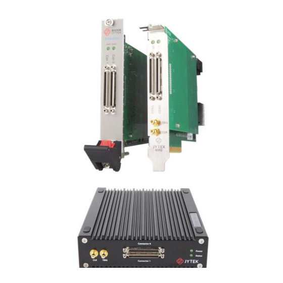
Table 7 Input Characteristics Timing and Trigger Table 8 Timing and Trigger Specification Front Panel conections and Pinout Definition Figure 6 PXIe/PCIe 6302 Front Panel PCIe/PXIe-6302 | jytek.com | 13... - Page 19 JY6302 provides 32 channels of thermocouple measurements and 4 digital input channels (for digital triggering). Table 9 Pinout defination PCIe/PXIe-6302 | jytek.com | 14...
-
Page 20: Channel Groups
Channel Groups JY6302 has 4 groups, each supports 8 channels as shown in Table 10. Table 10 JY6302 channel groups Physical and Environment Table 11 Physical and Environment PCIe/PXIe-6302 | jytek.com | 15... -
Page 21: Software
Windows 10 whenever possible. Linux Kernel Versions: There are many Linux versions. It is not possible JYTEK can support and test our devices under all different Linux versions. JYTEK will at the best support the following Linux versions. -
Page 22: C# Programming Language
DAQ hardware using the same methods. Install the SeeSharpTools from JYTEK To efficiently and effectively use JY6302 boards, you need to install a set of free C# utilities from JYTEK SeeSharp Test and Measurement platform. The SeeSharp platform offers rich user interface functions you will find convenient in developing your applications. -
Page 23: Running C# Programs In Linux
If you want to use your own Linux development system other than Mono, you can do it using our Linux driver. However, JYTEK does not have the capability to support the Linux applications. JYTEK completely relies upon Microsoft to maintain the cross-platform compatibility between Windows and Linux using Mono. -
Page 24: Operating Jy6302 Module
Platform) to operate the JY6302 board. If you are already familiar with Microsoft Visual Studio and C# programming, the quickest way to use JY6302 cards is to go through our extensive examples. We provide source code of our examples. In many cases, you can modify the source code and start to write your applications. - Page 25 (Ch0~Ch31) in sequence, and these channels are automatically assigned to four ADCs. At the beginning of the acquisition task, each ADC will start working at the same time, converting the channels in its group in turn. Figure 7 Typical channel scan sequence PCIe/PXIe-6302 | jytek.com | 20...
-
Page 26: Sample Rates And Noise Reduction
6.2.2 Sample Rates and Noise Reduction JY6302 offers 6 fixed sample rates as shown in Table 1. When a user select a sampe rate, the driver software will use it if it is one of these 6 sample rates. If it is not, the driver software will use the next higher sample rate. - Page 27 Connect the K-type Thermocouple’s positive pole and negative pole to Terminal Block’s TC1+ (Pin#37) and TC1- (Pin#3); Open Winform AI Continuous Raw Data. Set the other parameters as shown; Figure 9 AI Continuous Raw Data Paraments Click Start. The result is shown below. PCIe/PXIe-6302 | jytek.com | 22...
- Page 28 Figure 10 Continuous Raw Data Acquisition PCIe/PXIe-6302 | jytek.com | 23...
-
Page 29: Cold-Junction Compensation
When the user starts a task, JY6302 will simultaneously scan the cold-junction temperature (reference temperature) and store the data in the onboard memory. When the user reads the data, the JY6302 driver will automatically pair the measurement channel data with the cold-junction channel data for cold-junction compensation. -
Page 30: Open Thermocouple Detection
The thermocouple open circuit detection function is provided in the driver to help the user detect the connection status of the thermocouple. When the user calls the method PerformOpenThermocoupleDetection, JY6302 outputs 0.5 µA/ 2 µA/ 4 µA (software configurable) excitation current on all TC+ terminals, traversing each enabled channel for voltage acquisition. - Page 31 Figure 12 Open Thermocouple Detection Status indicates the current working state of the channel. PCIe/PXIe-6302 | jytek.com | 26...
-
Page 32: Trigger Source
Connect the K-type Thermocouple’s positive pole and negative pole to Terminal Block’s TC1+ (Pin#37) and TC1- (Pin#3), then connect the signal source’s positive pole and negative pole to JY6302 PFI0 (Pin#64) and GND (Pin#30); Set the signal source Ch1’s output to square wave (f=1Hz, Vpp=5v);... - Page 33 Figure 14 Digital Trigger Paraments Trigger Source must match the pin on the terminal block. There are two Trigger Conditions: Rising and Falling. The result shows below: PCIe/PXIe-6302 | jytek.com | 28...
- Page 34 Figure 15 Digital Trigger Acquisition Since the squarewave is used for the digital trigger source, when a rising edge of the squarewave occurs, the digital trigger will be activated, and the data acquisition will start. PCIe/PXIe-6302 | jytek.com | 29...
-
Page 35: Trigger Mode
Trigger Mode JY6302 supports several trigger modes: Start Trigger, Reference Trigger and Retrigger. 6.6.1 Start Trigger In this mode, the analog acquisition task will start to acquire the signal immediately after the trigger asserted as shown in Figure 16. The Start Trigger mode is suitable for continuous acquisition and finite acquisition mode. - Page 36 Figure 17 AI Continuous Paraments When Start is clicked, it generates a start trigger, which starts the acquisition. The result is shown below. Figure 18 Signel Channel Continuous Acquisition PCIe/PXIe-6302 | jytek.com | 31...
-
Page 37: Reference Trigger
For example, we set the ReTriggerCount to N and the length of each acquisition to M, therefore the total acquired samples is N * M * channelcounts as shown in Figure 20. Note, Retrigger mode is only valid in finite acquisition mode. PCIe/PXIe-6302 | jytek.com | 32... -
Page 38: Learn By Example 6.6.2 And 6.6.3
Connect the K-type Thermocouple’s positive pole and negative pole to Terminal Block’s TC1+ (Pin#37) and TC1- (Pin#3), then connect the signal source’s positive pole and negative pole to JY6302 PFI 1 (Pin#65) and GND (Pin#31); Set the signal source Ch1’s output to squarewave signal (f=4Hz, 0-5V). - Page 39 Re-Trigger it can be used by changing the numbers in Retrigger Count. Now the Trigger Mode is “Reference”, and the PreTrigger Samples are 10. Click Start to begin the data acquisition, the result is shown below: PCIe/PXIe-6302 | jytek.com | 34...
- Page 40 Now change the mode of trigger to Retrigger through giving Retrigger Count the number 3 and click Start. A message will appear in the lower left corner: “Samples acquired: 200/300”. Figure 23 Retrigger Complete State It shows the acquisition process through every trigger signal. PCIe/PXIe-6302 | jytek.com | 35...
-
Page 41: System Synchronization Interface(Ssi)For Pcie Modules
DIP Switch in PCIe-6302 PCIe-6302 series Module has a DIP switch. The card number can be adjusted manually by changing the DIP switch setting, which is used to identify the boards with different slot position. PCIe/PXIe-6302 | jytek.com | 36... - Page 42 For example, if you want to set the card number to 3, you could turn the position 2 and 1 of the DIP switch to the ON position and the orthers to OFF. Find the detail below. Figure 25 DIP Switch in PCIe-6302 Table 14 Relationship between switch position and slot number PCIe/PXIe-6302 | jytek.com | 37...
-
Page 43: Calibration
7. Calibration JYTEK 6302 boards are precalibrated before the shipment. We recommend you recalibrate JY6302 board periodically to ensure the measurement accuracy. A commonly accepted practice is one year. If you need to recalibrate your board, please contact JYTEK. PCIe/PXIe-6302 | jytek.com... -
Page 44: Using Jy6302 In Other Software
C#, we recognize there are other platforms that are either becoming very popular or have been widely used in the data acquisition applications. Among them are Python, C++. This chapter explains how you can use JY6302 DAQ card using one of this software. -
Page 45: Voltage Bias
AD acquisition circuit, so as to obtain an ideal dynamic range and accuracy. JY6302 uses an asymmetrical power rail design (the midpoint voltage value is used as the voltage offset), and can adjust its own circuit configuration to achieve the best state according to the type of input sensor and signal conditions. -
Page 46: Thermocouple Measurement Noise
As shown in Figure 27. Figure 27 Ground loops generate common mode noise PCIe/PXIe-6302 | jytek.com | 41... -
Page 47: Normal Mode Noise
The normal mode current is reduced by filtering. 9.2.3 Electrostatic Noise Electrostatic noise is noise coupled into the measurement path through parasitic capacitance. Electrostatic noise is caused by rotating equipment, generating AC currents that couple capacitively into the measurement path. Parasitic capacitance PCIe/PXIe-6302 | jytek.com | 42... -
Page 48: Influence Of Thermocouple Type On Measurements
The thermocouple probe is formed by thermocouple wire built into metal tube. Thermocouple can be divided into three types according to the type of connection point:grounded、exposed and ungrounded. As shown in Figure 30. Figure 30 Three Thermocouple Types PCIe/PXIe-6302 | jytek.com | 43... -
Page 49: Thermocouple Installation Method
A thermocouples must be correctly installed to achieve good and intended measurement results. The following points should be paid attention to during installation: Insertion depth, the thermocouple measuring end is inserted into the temperature position of the measured medium; PCIe/PXIe-6302 | jytek.com | 44... - Page 50 45°; For the installation location, try to choose a location away from heat sources, electric fields and strong magnetic fields. PCIe/PXIe-6302 | jytek.com | 45...
-
Page 51: About Jytek
About JYTEK JYTEK China Founded in June 2016, JYTEK China is a leading Chinese test & measurement company, providing complete software and hardware products for the test and measurement industry. The company is a joint venture between Adlink Technologies and a group of experienced professionals form the industry. JYTEK independenly develop the software and hardware products and is entirely focused on the Chinese market. -
Page 52: Jytek Software Platform
FirmDrive, upon which many our future hardware will be based. In addition to our own developed hardware, JYTEK also rebrands Adlink’s PXI product lines. In addition, JYTEK has other rebranding agreements to increase our hardware coverage. It is our goal to provide the complete product coverage in PXI and PCI modular instrumentation and data acquisition. -
Page 53: Statement
11. Statement The hardware and software products described in this manual are provided by JYTEK China, or JYTEK in short. This manual provides the product review, quick start, some driver interface explaination for PCIe/PXIe-6301 family of temperature sensor data acquisition cards.
Need help?
Do you have a question about the JY6302 and is the answer not in the manual?
Questions and answers