Advertisement
Quick Links
QuickLogic Thing Plus (EOS S3) Hookup Guide
Introduction
Note: Content for this user guide was originally written by QuickLogic.
This guide provides users with functional descriptions, configuration options for the QuickLogic Thing Plus EOS
S3. It also serves as a "Getting Started" and "How To" guide.
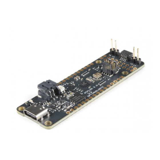
SparkFun QuickLogic Thing Plus - EOS S3
DEV-17273
Product Showcase: SparkFun QuickLogic Thing Plus
Product Showcase: SparkFun QuickLogic Thing Plus
Advertisement

Related Manuals for sparkfun QuickLogic Thing Plus


Summary of Contents for sparkfun QuickLogic Thing Plus
- Page 1 Introduction Note: Content for this user guide was originally written by QuickLogic. This guide provides users with functional descriptions, configuration options for the QuickLogic Thing Plus EOS S3. It also serves as a “Getting Started” and “How To” guide. SparkFun QuickLogic Thing Plus - EOS S3 ...
- Page 2 To follow along with this tutorial, you will need the following materials. You may not need everything though depending on what you have. Add it to your cart, read through the guide, and adjust the cart as necessary. SparkFun QuickLogic Thing Plus - EOS S3 Reversible USB A to Reversible Micro-B Cable - 0.8m...
-
Page 3: Hardware Overview
Qwiic Connect System If you aren’t familiar with the following concepts, we also recommend checking out a few of these tutorials before continuing. Serial Peripheral Interface (SPI) Logic Levels SPI is commonly used to connect microcontrollers to Learn the difference between 3.3V and 5V devices and peripherals such as sensors, shift registers, and SD logic levels. - Page 4 The QuickLogic Thing Plus EOS S3 is a small form factor system ideal for enabling the next generation of low- power Machine Learning (ML) capable Internet of Things (IoT) devices. Unlike other development boards which are based on proprietary hardware and software tools, the QuickLogic Things Plus is based on 100% open source hardware, compatible with the Feather form factor, and is built around 100% open source software (including the Symbiflow FPGA Tools).
- Page 5 EOS S3 MCU IO Map to QuickLogic Thing Plus Below is the graphical datasheet of the QuickLogic Thing Plus EOS S3 to reference the pins followed by a table listing the EOS S3 pins. Due to the size of the board and components, the silkscreen is printed on the back of the board.
- Page 6 IO_6 User Button Input J8.10 IO_7 J8.11 IO_8 J8.12 IO_10 J8.13 IO_11 J8.6 IO_12 J8.7 IO_13 J6.8 IO_14 Serial Wire Debug CLK J6.4 IO_15 Serial Wire Debug DATA J6.2 IO_16 SPI Peripheral CLK J9.8 IO_17 SPI Peripheral CIPO (input) J9.7 IO_18 Blue LED IO_19...
- Page 7 IO_34 SPI Controller CLK J6.6 IO_36 SPI Controller CIPO J6.4 IO_38 SPI Controller COPI (flash) J6.5 IO_40 IO_43 Interrupt Output to Host J9.9 IO_44 UART TX J6.2 IO_45 UART RX J6.3 Connector J9 EOS S3 MCU IO BGA Pin# Function VBAT 3.3V Circuit Enable VBUS...
- Page 8 IO_43 EOS S3 Interrupt Output IO_3 Accel Interrupt input IO_0 I2C0 SCL IO_1 I2C0 SDA Connector J6 EOS S3 MCU IO BGA Pin# Function Ground IO_44 S3 UART TX IO_45 S3 UART RX IO_36 SPI Controller CIPO input IO_38 SPI Controller COPI output IO_34 SPI Controller CLK output IO_2...
- Page 9 No Connect Ground No Connect +3.3V SYS_RSTn EOS S3 HW reset input Connector J8 EOS S3 MCU IO BGA Pin# Function IO_28 PDM microphone Data IO_29 PDM microphone CLK IO_23 I2S Peripheral WCLK Input IO_24 I2S Peripheral DATA output IO_31 I2S Peripheral CLK input IO_11 IO_12...
- Page 10 IO_7 IO_8 IO_10 IO_35 +3.3V Ground +3.3V Ground Development Connector EOS S3 MCU SWD Connector Below is the SWD connector used to program the board. Taken from the graphical datasheet are the pin labels on the right for reference. EOS S3 MCU IO Function +3.3V IO_15...
- Page 11 Install both shunts to use SWD Debugger for development Remove both shunts for boot-from-flash Note: QuickLogic Thing Plus board flash device must contain valid boot image for successful boot from flash. Power...
- Page 12 There are two ways to provide power to the QuickLogic Thing Plus: USB connector (J5) or Battery connector (J4). When both ports are connected at the same time, the USB power activates the battery charging circuit that provide charging current to the battery.
- Page 13 J2. You can also access the pins along the J9 header. QuickLogic Thing Plus I C supports I C Standard mode (100KHz) and Fast mode (400KHz). There is one I C bus available; additional I C IP can be implemented in EOS S3 FPGA.
- Page 14 The accelerometer INT1 pin is connected to pin 3. Sensor with SPI Peripheral Port QuickLogic Thing Plus board supports connecting to sensor module with SPI peripheral interface via expansion connectors J6 and J9: SPI CONTROLLER CLK (J6 pin 6), SPI CONTROLLER CIPO (J6 pin 4), SPI...
- Page 15 PDM CLK). Based on the design of the microphone, there is a drill hit through the board that allows an opening for the sound. QuickLogic Thing Plus supports external PDM microphone connection via expansion connector J8: PDM CLK (J8 pin 2) and PDM DATA (J8 pin 1).
- Page 16 To support two external PDM microphones configuration, it is required to disable the connection of the on-board PDM microphone. QuickLogic Thing Plus supports external PDM microphone connection via expansion connector J8: PDM CLK (J8 pin 2) and PDM DATA (J8 pin 1).
-
Page 17: Hardware Assembly
Running this test takes less than a minute to do, requires no knowledge of the QuickLogic Thing Plus, and will give you peace of mind the QuickLogic Thing Plus is ready for you to start innovating freely. - Page 18 Note: For Win10 system, the system device manager may not fully configure QuickLogic Thing Plus as COM port when install for the first time, repeat step (3) to (6). 7. Launch PuTTY application and configure for Serial access and select “Open”.
- Page 19 Download Binaries using JLink SWD QuickLogic Thing Plus supports loading and testing stand-alone eFPGA design or eFPGA + M4 MCU design, using SWD standard tool such as Segger’s Jlink SWD or OCD. Below are the instructions for system with Windows 10 OS with Segger Jlink pod.
- Page 20 Install shunts at QuickLogic Thing Plus J2 and J3 Connect micro USB cable from QuickLogic Thing Plus to PC Connect 10-pin cable to QuickLogic Thing Plus connector J7; check connector key for correct alignment Press reset button Open CMD console (#1) Launch Jlink commander (i.e.
- Page 21 TensorFlow Lite SensiML Real-time Operating Systems Zephry RTOS (QuickLogic Fork) QORC SDK with FreeRTOS FPGA Tools SymbiFlow GitHub Hardware Repo Product Showcase Need some inspiration for your next project? Check out some of these related tutorials: Programming an FPGA Come look at the basics of working with Field Programmable Gate Arrays.
Need help?
Do you have a question about the QuickLogic Thing Plus and is the answer not in the manual?
Questions and answers