Table of Contents
Advertisement
Advertisement
Table of Contents

Related Manuals for Fancom 743


Summary of Contents for Fancom 743
- Page 1 INSTALLER MANUAL VERSION C3...
- Page 2 Fancom be liable for any damages in excess of the amount paid for the products. In the event a defect is found by the Manufacturer to exist within this period, the Manufacturer will, at its option, (a) repair or replace such product free of charge, F.O.B.
-
Page 3: Table Of Contents
Fancom 743 Table of contents Table of contents About this manual 1. Introduction ............................1 2. Technical specifications ........................2 3. Safety instructions and warnings ..................... 3 3.1 General ............................3 3.2 During installation ........................3 3.3 During repairs ..........................3 3.4 Independent alarm system ...................... -
Page 4: About This Manual
The installer’s settings can then be entered and the computer prepared for further use. This manual has been written by Fancom for the installer. A user’s manual is also available for the user. The user’s manual contains information about the daily use of the computer. -
Page 5: Introduction
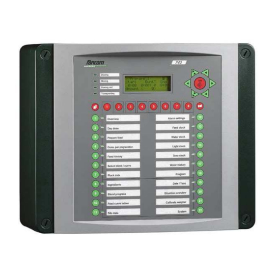
Fancom 743 1. Introduction 1. Introduction The Fancom 743 is a feed mixing computer for the poultry sector. It is suitable for fully automatic control of a feed mixing installation. Maximum installation size 12 stock silos ♦ 12 ingredients ♦... -
Page 6: Technical Specifications
Communication FNet, Fancom network, for intercommunication of control computers and PC connection*. Optional: Fancom serial loop for intercommunication of control computers and PC connection* I/O-Net for extra in and outputs using I/O-modules; max. 30 IDM and/or IRM-modules, each with 16 in/outputs*. -
Page 7: Safety Instructions And Warnings
Fancom takes no responsibility for any possible damage as a result of incorrect settings and a non- or partially functioning installation. -
Page 8: Mounting And Installation
Fancom 743 INSTALLER: 4. Mounting and installation 4. Mounting and installation Caution It is essential that the alarm outputs of each computer are connected to a separate alarm system circuitry. When mounting the computer, the following should be observed: 1. Never mount the computer near water pipes, drainage pipes etc. -
Page 9: System Settings
Fancom 743 INSTALLER: 5. System settings 5. System settings 5.1 General The system settings are intended for the installer. Normally the user will never have to change these settings, with the exception of the password. The system settings are not for daily use. The installer makes these settings when the weighing computer is installed. -
Page 10: Configuration
Enter the unit of temperature: °C = degrees Celsius °F = degrees Fahrenheit Unit windspeed Enter the unit of wind speed: m/s = metres per second Mph = miles per hour (1 m/s ~ 2.24 Mph). Version: 743 software version number. -
Page 11: Communication
Fancom 743 INSTALLER: 5. System settings 5.2.2 Communication >>Communication Computer number Type: SLAVE Baud rate 2400 Bd Comm R: 0 T: Network status Computer If the computer is part of a loop or network, each computer should have its number own, unique number. -
Page 12: Installation
Fancom 743 INSTALLER: 5. System settings 5.3 Installation 5.3.1 General A number of settings and assignments are made concerning the installation. Fancom divides the installation settings into ten groups: >>Installation 1 General 2 Silo 3 Additive 4 Weigher 5 Circuit... -
Page 13: Silo
When dosing in has stopped certain ingredients can still fall into the weigher (after flow). This after flow is a computer calculated value. When the 743 is started the after flow is 0.0kg. Enter an (estimated) after flow for the first time the 743 is put into operation. -
Page 14: Weigher
Fancom 743 INSTALLER: 5. System settings 5.3.4 Weigher >>Weigher 3× Weigher content 0. 0 Valve status CLOSE Motor control Weigher type WHOP-RIN Weigher tare 0.000 Capacity Address ILM Counts Zero/offset Span Filter Stable 0.000 Hopper Max.sensor 0. 0 Min.sensor 0. 0... - Page 15 Fancom 743 INSTALLER: 5. System settings Counts The weighing bar signal (rough measurement). Zero/Offset A calculated value corresponding to the zero setting of the ILM.x/weigher combination. Span (Cal.) A calculated value corresponding to the calibrated ILM.x/weigher combination. Span Zero/Offset The computer uses the values of and the rough ...
-
Page 16: Circuit
Fancom 743 INSTALLER: 5. System settings 5.3.5 Circuit >>Circuit_1 4× Relay output 0. 0 Status Extra distance 0:00 next circuit (max. 2 circuits) % slip previous circuit Relay output Enter the address (in front of the point) and the relay number (behind the point) to which the circuit inlet valve control has been connected. -
Page 17: Storage Silo
Fancom 743 INSTALLER: 5. System settings 5.3.6 Storage silo >>Storage silo >>Storage silo 5× Circuit number Port.to max.sens Circuitnummer Port.to fill.sens Port.tot max.sens Valve position 0:00 Port.tot afv.sens Reverse valve Positie klep 0:00 Auger aft.run. 0:00 Omschakel.klep 0:00 Stor.silo dem. - Page 18 Fancom 743 INSTALLER: 5. System settings Stor. silo dem. FULL The storage silo is full. DEMAND The storage silo demands blend preparation. FILL Filling sensor covered Max. sensor FULL FULL Max. sensor FULL Max. sensor DEMAND Filling sensor DEMAND DEMAND FILL Min.
-
Page 19: Feed Clock
Fancom 743 INSTALLER: 5. System settings The following settings are important in registration mode. %Tolerance A factory setting used by the computer to determine the batch amount. Batch am. The amount of feed to be fed according to the daily norm × the tolerance percentage. -
Page 20: Water Clock
Fancom 743 INSTALLER: 5. System settings 5.3.8 Water clock >>Water clock 7× Pulse input 0. 0 Relay output 0. 0 Status Unit/pulse Pulse input Enter the address (in front of the point) and the digital input number (behind the point) to which the water pulse counter has been connected. -
Page 21: Time Clock
Fancom 743 INSTALLER: 5. System settings 5.3.10 Time clock >>Time clock 9× Relay output 0. 0 Status Relay output Enter the address (in front of the point) and the relay number (behind the point) to which the time clock control has been connected. -
Page 22: Appendix 1: System Alarms
Fancom 743 APPENDIX 1: System alarms APPENDIX 1: System alarms The following alarms are system alarms. The computer regularly carries out a number of tests concerning the functioning of the computer itself. If the computer detects an error, an alarm will be given and action taken. -
Page 23: Appendix 2: Installation Report
Fancom 743 APPENDIX 2: Installation report APPENDIX 2: Installation report User Installer Name: Name: Address: Address: Place: Place: Installation Data Date: Type computer: Program version: System 1. Configuration 2. Installation 3. Internal RAM 1. Configuration 1. General Setting Sec. - Page 24 Fancom 743 APPENDIX 2: Installation report 2. Installation 2. Silo_1...12 Relay output ..Status Wait time inc. ..:.. Min.inc./30sec ..,. After flow ..,. Wait aft.dos.in ..:.. Sec. 5.3.2 5.3.2 5.3.2 5.3.2 5.3.2 5.3.2 2. Installation 3. Additive_1...4 Sec.
- Page 25 Fancom 743 APPENDIX 2: Installation report 2. Installation 6. Storage silo Sec. 5.3.6 Circuit number 5.3.6 Port.to max.sens 5.3.6 Port.to fill.sens 5.3.6 Valve position ..:.. 5.3.6 Reverse valve ..:.. 5.3.6 Auger aft. run ..:..
- Page 26 Fancom 743 APPENDIX 2: Installation report 2. Install. 7. Feed clock Sec. 5.3.7 Relay output ..5.3.7 Status 2. Install. 7. Feed clock Sec. ...
-
Page 27: Appendix 3: Possible Dosing Out Situations
Fancom 743 APPENDIX 3: Possible dosing out situations APPENDIX 3: Possible dosing out situations Directly into storage silo; selection via switch valve above storage silo. If the storage silo to be filled is the same as the last storage silo filled, do not switch the valve. - Page 28 Fancom 743 APPENDIX 4: Connection diagrams...
- Page 29 Fancom 743 APPENDIX 4: Connection diagrams...
- Page 30 Fancom 743 APPENDIX 4: Connection diagrams...
- Page 31 Fancom 743 APPENDIX 4: Connection diagrams...
Need help?
Do you have a question about the 743 and is the answer not in the manual?
Questions and answers