Table of Contents
Advertisement
Quick Links
Advertisement
Table of Contents

Related Manuals for Crestron CWD07234


Summary of Contents for Crestron CWD07234
- Page 1 Crestron CWD07234 Two-Way RF Transceiver Module Operations Guide...
- Page 2 équivalente (p.i.r.e.) ne dépasse pas l'intensité nécessaire à l'établissement d'une communication satisfaisante. Le présent émetteur radio , IC: 5683C-CWD07234, a été approuvé par Industrie Canada pour fonctionner avec les types d'antenne énumérés ci-dessous et ayant un gain admissible maximal et l'impédance requise pour chaque type d'antenne.
-
Page 3: Table Of Contents
Crestron CWD07234 Two-Way RF Transceiver Module Contents Two-Way RF Transceiver Module: CWD07234 ..........1 Functions and Features ......................1 Specifications ..........................2 Physical Description ........................3 Ports ..........................4 Power/I-O ........................5 Labeling Requirements ......................5 ... -
Page 5: Two-Way Rf Transceiver Module: Cwd07234
The module operates according to the IEEE 802.15.4 specification and can be configured to minimize the possibility of interference with other devices. The module receives RF signals from one or more Crestron devices and can transmit these signals over the air or over a cable run for further processing (depending on the application). -
Page 6: Specifications
Two-Way RF Transceiver Module Crestron CWD07234 Specifications The table below is a summary of specifications for the CWD07234. Specifications of the CWD07234 SPECIFICATION DETAILS Power Requirements 1.35 W (5.0 Vdc @ 0.27 A) Operating Frequency 2400 MHz to 2483.5 MHz (802.15.4 compliant) -
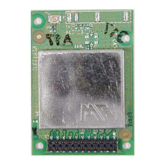
Page 7: Physical Description
The module consists of various components on a printed circuit board (PCB). There are two build options: 1. An onboard antenna (refer to CWD07234-1) 2. A detached antenna (refers to CWD07234-2) The detached antenna connects to the PCB through a 3 inch cable to a U.FL connector. -
Page 8: Ports
Two-Way RF Transceiver Module Crestron CWD07234 Physical View of CWD07234-2 Ports The module contains an 11-pin double row connector. Refer to the diagram that follows. CWD07234 Power / I-O Pin Configuration 4 Two-Way RF Transceiver Module: CWD07234 Operations Guide - DOC. 7520A... -
Page 9: Power/I-O
20 cm from all persons and must not be co-located or operating in conjunction with any other antenna or transmitter.” Two-Way RF Transceiver Module: CWD07234 5 Operations Guide - DOC. 7520A... - Page 10 Crestron Electronics, Inc. Operations Guide – DOC. 7520A 15 Volvo Drive Rockleigh, NJ 07647 Tel: 888.CRESTRON 03.13 Fax: 201.767.7576 Specifications subject to www.crestron.com change without notice.
Need help?
Do you have a question about the CWD07234 and is the answer not in the manual?
Questions and answers