Advertisement
Quick Links
Advertisement

Related Manuals for Crestron CWD7567


Summary of Contents for Crestron CWD7567
- Page 1 Crestron CWD7567 Two-Way RF Transceiver Module Operations Guide...
- Page 2 À 20 centimètres de toutes les personnes et ne doit pas être collocée ou fonctionner en conjonction avec une autre antenne ou émetteur. All brand names, product names and trademarks are the property of their respective owners. ©2010 Crestron Electronics, Inc.
- Page 3 Crestron CWD7567 Two-Way RF Transceiver Module Operations Guide...
-
Page 5: Table Of Contents
Crestron CWD7567 Two-Way RF Transceiver Module Contents Two-Way RF Transceiver Module: CWD7567 ..........1 Functions and Features ......................1 Specifications ........................2 Physical Description ......................2 Setup ............................ 4 Labeling ..........................4 Documentation ........................5 Contents • i Operations Guide - DOC. 7019A... -
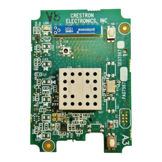
Page 7: Two-Way Rf Transceiver Module: Cwd7567
The module operates according to the IEEE 802.15.4 specification and can be configured to minimize the possibility of interference with other devices. The module receives RF signals from one or more Crestron devices and can transmit these signals over the air for further processing (depending on the application). -
Page 8: Specifications
Two-Way RF Transceiver Module Crestron CWD7567 Specifications The table below is a summary of specifications for the CWD7567. Specifications of the CWD7567 SPECIFICATION DETAILS Power Requirements 0.34 Watts (5VDC @ 0.068A) Operating Frequency 2400 MHz to 2483.5 MHz (802.15.4 compliant) Operating Ranges¹... - Page 9 Refer to the following table for pin assignments of the module interface connector. NOTE: Pin 1 provides power to the circuit card. Power/I-O Pinout Signals Pin # Signal Pin # Signal RELAY_ON DISABLE_SINK DISABLE_SOURCE 3.0V RELAY_OFF ANALOG_FB Two-Way RF Transceiver Module: CWD7567 • 3 Operations Guide - DOC. 7019A...
-
Page 10: Setup
This exterior label can use wording such as the following: “Contains Transmitter Module FCC ID: EROCWD7567” or “Contains FCC ID: EROCWD7567.” Any similar wording that expresses the same meaning may be used. 4 • Two-Way RF Transceiver Module: CWD7567 Operations Guide - DOC. 7019A... -
Page 11: Documentation
20 cm from all persons and must not be co-located or operating in conjunction with any other antenna or transmitter.” Two-Way RF Transceiver Module: CWD7567 • 5 Operations Guide - DOC. 7019A... - Page 12 This page intentionally left blank Crestron Electronics, Inc. Operations Guide – DOC. 7019A 15 Volvo Drive Rockleigh, NJ 07647 Tel: 888.CRESTRON 03.10 Fax: 201.767.7576 Specifications subject to www.crestron.com change without notice.
- Page 13 Crestron CWD7567 Two-Way RF Transceiver Module Two-Way RF Transceiver Module: CWD7567 • 7 Operations Guide - DOC. 7019A...
Need help?
Do you have a question about the CWD7567 and is the answer not in the manual?
Questions and answers