Table of Contents
Advertisement
Quick Links
Advertisement
Table of Contents

Related Manuals for Crestron CNRFGWX


Summary of Contents for Crestron CNRFGWX
-
Page 3: Table Of Contents
Programming ... 9 Problem Solving ... 12 Troubleshooting ... 12 Further Inquiries... 13 Syntax... 13 Return and Warranty Policies... 15 Merchandise Returns / Repair Service ... 15 CRESTRON Limited Warranty ... 15 Operations Guide - DOC. 5701 CRESTRON Contents • i... -
Page 5: Two-Way Rf Transceiver
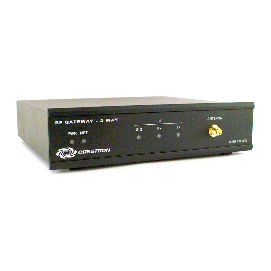
‘drop-out’ by automatically scanning for the best frequency. Physical Description The CNRFGWX, shown after this paragraph, is housed in a black enclosure with silk-screened labels on the front and rear panels. On the front of the unit there are five LEDs for indicating the unit’s current status. - Page 6 CRESTRON CNRFGWX Physical Views CNRFGWX Ports Three network ports are provided on the back of the CNRFGWX. Each has a silk- screened label. Refer to illustration and descriptions below. CNRFGWX Ports NOTE: All CRESNET (NET) connectors, modular and four-wire, can be used simultaneously.
- Page 7 Drawing (Doc. 5411). CNRFGWX Indicators There are five LED indicators located on the front panel of the CNRFGWX. Refer to illustration and descriptions below. The front panel also has a connector which attaches to the supplied antenna and is used to transmit and receive RF signals from the Spectrum touchpanels.
-
Page 8: Leading Specifications
Leading Specifications The table below provides a summary of leading specifications for the CNRFGWX. Dimensions and weight are approximations rounded to the nearest thousandth unit. Leading Specifications of the CNRFGWX Power Requirements CRESNET II Workshop CRESNET II Operating System STS VisionTools for Windows Compiler Dimensions &... -
Page 9: Setup
CODE specified in the “NET.ID” statement of the CRESNET II SIMPL-I program in order for the device to be addressed properly. The NET ID of each CNRFGWX has been factory set to 24, but may be changed from the PC via STS VisionTools™... - Page 10 Changing the NET ID - CNRFGWX Workshop Screens (1 of 3) Changing the NET ID - CNRFGWX Workshop Screens (2 of 3) Changing the NET ID - CNRFGWX Workshop Screens (3 of 3) 6 • Two-Way RF Transceiver CRESTRON 3. Enter the old NET ID code (in two-digit hexadecimal format) and depress ENTER.
- Page 11 Spectrum touchpanels. There are 16 possible codes for the CNRFGWX ranging from 0 to F (hexadecimal number). The CNRFGWX RF CHANNEL is factory set to “0”. The code can be changed via the CRESNET II Workshop while the CNRFGWX is connected to the network.
-
Page 12: Preparation For Use
Changing the RF CHANNEL - CNRFGWX Workshop Screens (3 of 3) Preparation for Use Refer to the hookup diagram below which illustrates the CNRFGWX connections to the CRESNET II system. Other than making the power connection last, complete the connections in any order. -
Page 13: Programming
The objects that are used in SIMPL are called symbols. The block diagram shown below exemplifies use of the CNRFGWX in a simple volume control application where UP and DOWN ramp a bargraph to an ST-VC, volume/tone control module, with a time interval of five seconds. - Page 14 CRESTRON CNRFGWX Workshop Screens (1 of 5) CNRFGWX Workshop Screens (2 of 5) CNRFGWX Workshop Screens (3 of 5) 10 • Two-Way RF Transceiver Operations Guide - DOC. 5701...
- Page 15 CRESTRON CNRFGWX Workshop Screens (4 of 5) CNRFGWX Workshop Screens (5 of 5) Two-Way RF Transceiver • 11 Operations Guide - DOC. 5701...
-
Page 16: Problem Solving
Problem Solving Troubleshooting The table below provides corrective action for possible trouble situations. If further assistance is required, please contact a CRESTRON technical support representative. CNRFGWX Troubleshooting PWR LED does not illuminate. NET LED does not illuminate. NET LED is on, but unit does provide control. -
Page 17: Further Inquiries
Further Inquiries If after reviewing this Operations Guide for the CNRFGWX, you can not locate specific information, please take advantage of CRESTRON's award winning technical support team in your area. Dial one of the following numbers. For local support from exclusive Crestron factory-trained personnel in New Zealand call Amber Technologies at +649-410-8382. - Page 18 AN1 = <signal name> AN256 = <signal name> 14 • Two-Way RF Transceiver CRESTRON “ \First analog feedback to touchpanl \Last analog feedback to touchpanl Operations Guide - DOC. 5701...
-
Page 19: Return And Warranty Policies
CRESTRON shall not be liable to honor the terms of this warranty if the product has been used in any application other than that for which it was intended, or if it has been subjected to misuse, accidental damage, modification, or improper installation procedures.
Need help?
Do you have a question about the CNRFGWX and is the answer not in the manual?
Questions and answers