Table of Contents
Advertisement
Quick Links
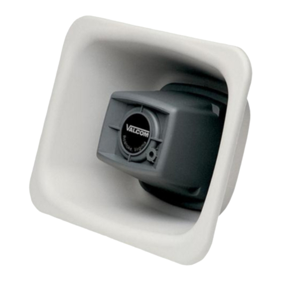
VIP-480L-IC InformaCast® Compliant
INSTALLATION
Mounting (VIP-LLE)
The VIP-LLE Network Extender is designed for wall
or shelf mounting and must be within 300 feet of the
network switch.
Shelf: Provided with the VIP-LLE Network Extender
are four rubber stick on pads. Peel pads off their
carrier backing and place at the four corners of the
bottom of the unit.
Wall: Using the brackets and wood screws
provided, secure the VIP-LLE Network Extender
to the wall.
Mounting (horn)
FLUSH MOUNT
The cardboard packing material in which the horn is
shipped also serves as the template for flush
mounting. Using the template, draw the speaker
outline on the wall to be cut. Make appropriate
wiring connections and test the speaker for
operation. Using appropriate mounting screws (not
furnished) drill and mount the flange as shown.
Loosen or separate the universal bracket leaves by
loosening or removing the handle and hardware.
Using the back leaf as a template, mark the wall
through the mounting holes. Drill and mount to the
wall using appropriate screws (not furnished) or
mount directly to a junction box.
Mount the T-bracket to the back of the horn as
shown using the (2) ½ inch screws provided.
"C" CLAMP FOR "I" BEAM MOUNTING
A "C" clamp is provided with the horn to allow
mounting to a beam. Attach the "C" clamp to the
back of the horn as shown using the (2) ½ inch
screws provided. Place the bolt through the hole in
the bottom of the base to secure the "C" clamp to
the beam. It is suggested that the horn be mounted
to the underside of the "I" beam to provide
maximum positioning adjustments.
IP Paging Horn
Interconnections
The only method of powering a VIP-480L-IC IP
Paging Horn is via a Power over Ethernet (PoE)
switch or power injector meeting the 802.3af
specification.
Make all required signal connections before
connecting to Ethernet switch or power injector
meeting the 802.3af specification. Power is
supplied to the horn assembly via the VIP-LLE
Network Extender.
Network Connection
As shown in Figure 1, the LLE Network Extender
has one RJ-45 network connector on the front
panel. Use a standard Ethernet patch cable to
connect the NETWORK connector of the LLE
Network Extender to a 802.3af compliant PoE port
(300 feet maximum distance).
Signal Connections
As shown in Figure 1 and 2, audio output
connections are made on the rear panel of the
LLE Network Extender. Versions of the LLE
Network Extender with the color-coded, 8-pin
screw connector will connect standard CAT-5
twisted-pair cable from the rear panel color coded
connector of the LLE Network Extender to the
supplied VM-186 RJ-45 connector (900 feet
maximum distance). Connect RJ-45 connector
of horn to VM-186 RJ-45 socket.
1
ISSUE 1
947730
Advertisement
Table of Contents

Related Manuals for Valcom InformaCast VIP-480L-IC


Summary of Contents for Valcom InformaCast VIP-480L-IC
- Page 1 ISSUE 1 VIP-480L-IC InformaCast® Compliant IP Paging Horn INSTALLATION Interconnections Mounting (VIP-LLE) The only method of powering a VIP-480L-IC IP The VIP-LLE Network Extender is designed for wall Paging Horn is via a Power over Ethernet (PoE) or shelf mounting and must be within 300 feet of the switch or power injector meeting the 802.3af network switch.
- Page 2 VALCOM LIMITED WARRANTY Valcom, Inc. warrants its products only to the original purchaser, for its own use, to be free from defects in materials and workmanship under conditions of normal use and service for a period of one year from the date of shipment. This Limited Warranty obligation shall be limited to the replacement, repair or refund of any such defective device within the warranty period, provided that: 1.
- Page 3 Note: The screw terminals are removable. Gently lift away from the circuit board to remove. Make the necessary wire connections, then replace the screw terminals over the pins Paging Horn RJ45 on circuit board. Front View BROWN BROWN ALCOM BROWN WHITE/BROWN VIP-LLE Status...
- Page 4 UNIVERSAL BRACKET SURFACE MOUNTED W ITH A UNIVERSAL BRACKET WITH CLAMP UNIVERSAL MOUNTING BRACKET "C" CLAMP FOR "I" BEAM MOUNTING ATTACH CLAMP TO HORN ATTACH FLEXHORN TO BEAM FLUSH MOUNT USING MOUNTING SCREWS: FLUSH MOUNTING IN A STUD W ALL USING THE TEMPLATE, MARK LOCATION OF INSTALLED W ITH MOUNTING SCREWS OPENING AND MOUNTING HOLES ON W ALL.
Need help?
Do you have a question about the InformaCast VIP-480L-IC and is the answer not in the manual?
Questions and answers