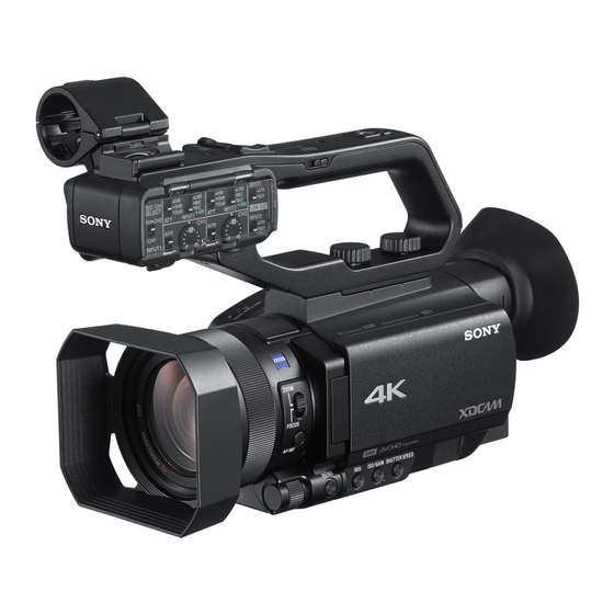
Sony HXR-NX80 Service Manual

Sony HXR-NX80 Service Manual

Solid-state memory camcorder
Hide thumbs Also See for HXR-NX80:
Table of Contents

Advertisement

SOLID-STATE MEMORY CAMCORDER
HXR-NX80
HXR-MC88
利用条件: 
①  本情報はソニー製品の販売、設置、設定、使用の目的でのみご利用ください。かかる目的以外での利用を禁止します。
②  著作者の事前の書面による許可なく、本情報の全部または一部の複写、複製、転載、改変、翻訳、送信等を禁止します。
情報改訂:
本情報は、当社の裁量により、予告なく変更されることがあります。ご使用される場合、本情報が最新の情報であることを確認のうえ、
ご使用ください。
Conditions of Use:
(1) Please use this information only for the purpose of sales, installation, configuration, and use of Sony products. Using this information
for any purpose other than the purpose described foregoing is forbidden.
(2) Do not copy, replicate, reproduce, alter, translate, transmit, sell, lease, or distribute this information in whole or in part without the prior
written permission of the author.
Revision of Information:
This information may be changed or updated at any time without any prior notice. Please confirm that this information is up-to-date before
using it.
SERVICE MANUAL
1st Edition (Revised 1)
®

Advertisement

Table of Contents
loading

Summary of Contents for Sony HXR-NX80

  • Page 1 ご使用ください。 Conditions of Use: (1) Please use this information only for the purpose of sales, installation, configuration, and use of Sony products. Using this information for any purpose other than the purpose described foregoing is forbidden. (2) Do not copy, replicate, reproduce, alter, translate, transmit, sell, lease, or distribute this information in whole or in part without the prior written permission of the author.
  • Page 2 électrique, d’incendie ou de blessure n’effectuer que les réparations indiquées dans le mode d’emploi à moins d’être qualifié pour en effectuer d’autres. Pour toute réparation faire appel à une personne compétente uniquement. Model Name Serial No. HXR-NX80(UC) 100001 and Higher HXR-NX80(J) 300001 and Higher HXR-NX80(CEE)
  • Page 3 Be sure to keep your PC used for service and checking of this 修理時に使用するパソコンは,ウィルス検出ソフトが常にアッ プデートを行っているパソコンを使用してください。もし,修 unit always updated with the latest version of your anti-virus software. In case a virus affected unit was found during service, 理を行うセット,もしくはパソコンがウィルスに感染している 事が判明した場合は,ソニーグループ内は社内技術相談窓口に, contact your Service Headquarters. 特約店様は特約店様専用電話窓口(修理窓口)にご相談くださ い。 HXR-NX80/HXR-MC88...
  • Page 4 CRITIQUES POUR LA SÉCURITÉ DE FONCTIONNEMENT. NE COMPONENTS WITH SONY PARTS WHOSE PART NUMBERS REMPLACER CES COMPOSANTS QUE PAR DES PIÈCES SONY APPEAR AS SHOWN IN THIS MANUAL OR IN SUPPLEMENTS DONT LES NUMÉROS SONT DONNÉS DANS CE MANUEL OU PUBLISHED BY SONY.
  • Page 5: Table Of Contents

    Cabinet (R) Assembly....................3-17 HXR-NX80/HXR-MC88...
  • Page 6 PD-1054 Board......................5-8 HXR-NX80/HXR-MC88...
  • Page 7 Power (4/5)..........................7-9 HXR-NX80/HXR-MC88...
  • Page 8 Frame Wiring (3/3)........................7-13 Revision History HXR-NX80/HXR-MC88...
  • Page 9: Purpose Of This Manual

    • Factory Service Manual (available on request) This manual describes the information on the premise the service based on the components parts of this unit. Trademarks System names and product names written in this manual are usually registered trademarks or trademarks of respective development manufacturers. HXR-NX80/HXR-MC88...
  • Page 11: Service Overview

    Section 1 Service Overview 1-1. Location of Boards HS-1003 HN-1004 XL-1005 PH-1004 CM-1016 MS-1037 LA-1003 FP-2269 SS-1006 IP-1002 EF-1003 VC-1045 FP-2401 GR-1003 WF-1008 ZM-1005 IR-1009 FP-2202 VF-1021 PD-1054 SW-1030 CK-1019 HXR-NX80/HXR-MC88...
  • Page 12: Service Tools

    1-2. Service Tools Part No. Name Usage/Note J-6325-110-A Torque screwdriver bit (M1.4/M1.7) Tightening screws J-6325-380-A Torque screwdriver bit (M2) J-6323-420-A Torque screwdriver bit (M2.6) J-6325-400-A Torque driver (3 kg・cm) (0.3 N・m) J-6252-510-A Torque driver (6 kg・cm) (0.6 N・m) HXR-NX80/HXR-MC88...
  • Page 13: Notes On Replacing The Part And Printed Wiring Board

    Start the Adjust Manual in the Adjust Station and execute the “PRODUCT ID & USB SERIAL No. INPUT” on the ADJUST tab. Update of MAC Address When a board that contains Wi-Fi has been replaced or when replacing a board that contains the main IC (CPU), the IC’s unique number (MAC address) must be reloaded. HXR-NX80/HXR-MC88...
  • Page 14: Notes For Replacing The Evf Display Device (Lcd902)

    LOAD AND WRITE] in the "ADJUSTMENT DATA BACKUP" on the DATA tab to write the extracted WB adjustment values. When replacing VC-1045 board (in case adjustment values cannot be read): Read the QR code printed in EVF display device (LCD902) using with “QR_Code_Reader_Ver1.0_x64”. HXR-NX80/HXR-MC88...
  • Page 15: Imager Dra Data

    Perform "Imager DRA Data Write" on the Adjust Manual 1-3-5. Precaution on Replacing the MS-1037 Board Angular Velocity Sensor Before replacing the board with a repairing board, be sure to record the sensitivity indicated on the angular velocity sensor on the repairing board. HXR-NX80/HXR-MC88...
  • Page 16: Checking The Wi-Fi Function

    In the following cases, perform the “Imager DRA EBC Adj” and “Imager SF2 adj” on the Adjust Manual, and write the imager DRA data. • When you cannot get the imager DRA data from the unit before replacing the VC board • When replacing the lens SF2 adjustment chart (J-6082-856-A) is required in "Imager DRA SF2 adj". HXR-NX80/HXR-MC88...
  • Page 17 EBC adjustment Get imager DRA data Perform "Imager DRA EBC adj" on the Adjust Manual SF2 adjustment Perform "Imager DRA SF2 adj" on the Adjust Manual Write the imager DRA data Perform "Imager DRA Data Write" on the Adjust Manual HXR-NX80/HXR-MC88...
  • Page 18: Circuit Protection Parts

    Part No. VC-1045 F0301 FUSE (1608/3.15 A) 1-523-393-11 F0302 FUSE (1608/2.0 A) 1-523-390-11 F0303 FUSE (1608/1.4 A) 1-523-389-11 F0304 FUSE (1608/1.4 A) 1-523-389-11 F0305 FUSE (1608/0.5 A) 1-523-385-11 F4001 FUSE, MICRO 1-523-038-31 F4101 FUSE, MICRO 1-523-038-31 F4102 FUSE, MICRO 1-523-038-31 HXR-NX80/HXR-MC88...
  • Page 19: Flexible Flat Cable, Flexible Board And Coaxial Cable

    Insert the flexible flat cable and flexible board firmly as far as them will go with the insulating surface facing upward. Close the latch of the connector in the direction of arrow B to lock the flexible flat cable and flexible board. HXR-NX80/HXR-MC88...
  • Page 20: Connecting/Disconnecting Coaxial Cable

    Be sure to hold the plug when disconnecting the coaxial cable. Do not pull the cable. Connecting Hold the plug to connect Connecting connector Hold the plug of coaxial cable. Connect the coaxial cable perpendicularly to the connector. Push the plug into the connector while turning it clockwise and counterclockwise several times. 1-10 HXR-NX80/HXR-MC88...
  • Page 21: Troubleshooting

    POWER/CHG lamp, Control switch SW board Control switch VC board CPU, Lens control, Wireless LAN module, Power control, Other function VF board EVF control WF board Wireless LAN antenna XL board Analog audio input ZM board Manual Ring control HXR-NX80/HXR-MC88...
  • Page 22: Self-Diagnosis Code Table

    Check both C: 32: 60 and E: 61: 10 of the self-diagnosis code. Continued Start the Adjust Manual in the Adjust Station and execute the “Destination data write” on the ADJUST tab. Function of this code is not provided in this unit. HXR-NX80/HXR-MC88...
  • Page 23 When the lens block was replaced, start the Adjust Manual in the Adjust Station and execute the necessary adjustment items. After the adjustment, make sure with the STEADYSHOT turned ON that the steadyshot functions appropriately in the handheld operation. HXR-NX80/HXR-MC88...
  • Page 24 The flash memory may be faulty. Replace the board that contains this peripheral circuit. Projector hardware error The peripheral circuit of the projector may be faulty. Replace the board that contains this peripheral circuit. Function of this code is not provided in this unit. HXR-NX80/HXR-MC88...
  • Page 25: Method Of Coping With Shift Lens Error

    Identify the cause of the problem (lens or VC-1045 board), and replace the faulty lens or the VC-1045 board. 2-2-4. E:62:20 Abnormality of Thermistor Check the connection between the lens block and VC-1045 board. Identify the cause of the problem (lens or VC-1045 board), and replace the faulty lens or the VC-1045 board. HXR-NX80/HXR-MC88...
  • Page 27: Replacement Of Main Parts

    M2.0 x 4: 0.18 ±0.02 N·m Tapping screw (M2.0 x 5): 0.18 ±0.02 N·m P2.6 x 5: 0.4±0.04 N·m When using the torque driver with the notation of cN·m, interpret it as follows. Example: 0.8 N·m = 80 cN·m HXR-NX80/HXR-MC88...
  • Page 28: Cabinet (G) Assembly

    3-2. Cabinet (G) Assembly Procedure Remove the seven screws, and then remove the cabinet (BM). Precision screws (P1.7 x 4) Cabinet (BM) HXR-NX80/HXR-MC88...
  • Page 29 (5) Disconnect the flexible flat cable from the connector (CN0901) on the LA-1003 board. HDMI lid Precision screws (P1.7 x 4) Flexible flat cable LA-1003 board Cabinet (G) assembly CN0901 Hooks Hooks USB lid Precision screws (P1.7 x 4) Belt Install the removed parts by reversing the steps of removal. HXR-NX80/HXR-MC88...
  • Page 30: Heat Sink (Gp) Assembly

    Disconnect the coaxial cable from the connector (J7391) on the WF-1008 board. Release the coaxial cable from the groove and rib of the inner mold (G). Remove the two screws. GR-1003 board Harness CN4651 Precision screws (P1.7 x 4) Inner mold (G) WF-1008 board J7391 Groove Coaxial cable HXR-NX80/HXR-MC88...
  • Page 31 Boss Hole Flexible flat cable ZM-1005 board CN4509 Heat sink (GP) assembly Note After installing the heat sink (GP) assembly, push the flexible board as shown in the figure. Install the removed parts by reversing the steps of removal. HXR-NX80/HXR-MC88...
  • Page 32: Gr-1003 Board

    (2) Disconnect the flexible board from the connector (CN4601) on the GR-1003 board. (3) Remove the gasket (BM) from the GR-1003 board. Boss Flexible board Hole CN4601 Boss Gasket (BM) Hole Precision screws GR-1003 board (P1.7 x 4) Install the removed parts by reversing the steps of removal. HXR-NX80/HXR-MC88...
  • Page 33: Top Cabinet Assembly

    “3-3. Heat Sink (GP) Assembly”.) Procedure Disconnect the flexible board and two flexible flat cables from the three connectors (CN4604, CN4605, CN4607) on the GR-1003 board. Flexible flat cable Flexible board CN4605 CN4604 GR-1003 board CN4607 Flexible flat cable HXR-NX80/HXR-MC88...
  • Page 34 (4) Disconnect the flexible board from the connector (CN4505) on the ZM-1005 board. Hook Precision screws Hole (P1.7 x 4) Top cabinet assembly Flexible board Position of screw Precision screws (P1.7 x 4) Precision screw (P1.7 x 4) CN4505 (ZM-1005 board) Install the removed parts by reversing the steps of removal. HXR-NX80/HXR-MC88...
  • Page 35: Ef-1003 Board

    “3-3. Heat Sink (GP) Assembly”.) Procedure Remove the EF cover. (1) Remove the two screws. (2) Release the two hooks, and then remove the EF cover. Precision screw (P1.7 x 4) EF cover Hooks Precision screw (P1.7 x 4) HXR-NX80/HXR-MC88...
  • Page 36 When installing the EF-1003 board, pass the flexible flat cable through the gap of the inner mold (T) assembly as shown in the figure, and then hook it on the hook. Install the removed parts by reversing the steps of removal. 3-10 HXR-NX80/HXR-MC88...
  • Page 37: Ir-1009 Board

    (1) Remove the screw. (2) Release the hook, and then release the projection of the IR cabinet assembly from the gap of the cabinet R. Hook Gap of the cabinet R IR cabinet assembly Projection Precision screw (P1.7 x 4) 3-11 HXR-NX80/HXR-MC88...
  • Page 38 (1) Remove the two screws, and then remove the IR-1009 board. (2) Disconnect the flexible board from the connector (CN0801) on the IR-1009 board. Projection Boss Hole IR-1009 board Flexible board CN0801 Precision screws (P1.7 x 4) Install the removed parts by reversing the steps of removal. 3-12 HXR-NX80/HXR-MC88...
  • Page 39: Inner Mold (T) Assembly

    Board”.) Procedure Disconnect the flexible board from the connector (CN4003) on the VC-1045 board. Arrangement of flexible board CN4003 (VC-1045 board) Flexible board Note When connecting the flexible board, push the flexible board as shown in the figure. 3-13 HXR-NX80/HXR-MC88...
  • Page 40 Precision screw (P1.7 x 4) Precision screw (P1.7 x 4) Turn the LCD as shown in the figure. Release the boss and two hooks, and then remove the hinge cabinet assembly. Boss Hook Hook Hinge cabinet assembly Hole 3-14 HXR-NX80/HXR-MC88...
  • Page 41 • Check that the flexible board passes under the inner mold (T). • Attach the tape AS (2040) to the position shown in the figure. • When using the new tape AS (2040), cut it to the designated size. 3-15 HXR-NX80/HXR-MC88...
  • Page 42 (2) Release the boss and three hooks, and then remove the inner mold (T) assembly. Precision screw (P1.7 x 4) Inner mold (T) assembly Hole Precision screw Precision screw (P1.7 x 4) (P1.7 x 5) (Red) Hooks Hook Boss Install the removed parts by reversing the steps of removal. 3-16 HXR-NX80/HXR-MC88...
  • Page 43: Cabinet (R) Section

    Disconnect the flexible flat cable from the connector (CN4104) on the VC-1045 board. Arrangement of flexible flat cable Flexible flat cable CN4104 (VC-1045 board) Note When installing the lens cover assembly, arrange the flexible flat cable as shown in the figure. 3-17 HXR-NX80/HXR-MC88...
  • Page 44 (2) Release the boss, and then remove the lens cover assembly. Precision screws Lens cover assembly (P1.7 x 4) Hole Precision screw (P1.7 x 4) Boss Remove the eight screws, and then top frame assembly. Precision screws (P1.7 x 4) Top frame assembly 3-18 HXR-NX80/HXR-MC88...
  • Page 45 (2) Release the two bosses and projection, and then open the cabinet (R) assembly. (3) Disconnect the flexible board from the connector (CN4701) on the CK-1019 board. Projection Cabinet (R) assembly Flexible board CN4701 Bosses (CK-1019 board) Install the removed parts by reversing the steps of removal. 3-19 HXR-NX80/HXR-MC88...
  • Page 46: Ck-1019 Board

    Disconnect the flexible board from the connector (CN4703) on the CK-1019 board. Flexible board CN4703 (CK-1019 board) Remove the six screws and open the LCD, and then remove the frame (R). Frame (R) Hook Tapping screws (P1.7 x 4) Tapping screws (P1.7 x 4) 3-20 HXR-NX80/HXR-MC88...
  • Page 47 Peel off the insulating sheet (CK). Insulating sheet (CK) Boss Remove the CK-1019 board. (1) Disconnect the speaker harness from the connector (CN4702) on the CK-1019 board. (2) Remove the CK-1019 board. CK-1019 board CN4702 Speaker harness 3-21 HXR-NX80/HXR-MC88...
  • Page 48 Align the two switches on the new CK-1019 board with the two knob positions on the cabinet (R) and install it. Switches CK-1019 board Cabinet (R) Boss Knobs Boss Install in the reverse procedure of steps 1 to 4 in procedure. 3-22 HXR-NX80/HXR-MC88...
  • Page 49: Pd-1054 Board

    Frame (R) LCD assembly Adhesive portion of the FP-2264 flexible board Precision screws (P1.7 x 4) Rotate the hinge assembly in the direction of the arrow, and then remove the two screws. Precision screws (P1.7 x 5) Hinge assembly 3-23 HXR-NX80/HXR-MC88...
  • Page 50 Release the eight hooks, and then remove the P cabinet C. P cabinet C Eight hooks Peel off the tape. Tape 3-24 HXR-NX80/HXR-MC88...
  • Page 51 (1) Disconnect the three flexible boards from the three connectors (CN3201, CN3202, CN8040) on the PD-1054 board. (2) Remove the two screws, and then remove PD-1054 board. Tapping screws (P1.7 x 4) CN3202 CN3201 CN8040 PD-1054 board Flexible boards Install the removed parts by reversing the steps of removal. 3-25 HXR-NX80/HXR-MC88...
  • Page 52: Display Module

    Remove the cabinet (R) assembly. (Refer to “3-9-1. Cabinet (R) Assembly”.) Remove the frame (R). (Refer to “3-9-2. CK-1019 Board”.) Remove the PD-1054 board. (Refer to “3-9-3. PD-1054 Board”.) Procedure Release the two hooks, and then remove the flexible clamp. Flexible clamp Hooks 3-26 HXR-NX80/HXR-MC88...
  • Page 53 (1) Remove the two screws, and then remove the LCD retainer. (2) Remove the LCD cushion and display module. LCD retainer Tapping screws (P1.7 x 4) LCD cushion Display module Boss Boss Install the removed parts by reversing the steps of removal. 3-27 HXR-NX80/HXR-MC88...
  • Page 54: Installation Of The Fp-2264 Flexible Board And Magnet

    Hinge assembly Adhesive tapes 2 times Adhesive tapes FP-2264 Adhesive tapes flexible board Mountain fold Install the hinge cover (U) /hinge cover (O). Valley fold Hinge cover (U) Hinge cover (O) 3-28 HXR-NX80/HXR-MC88...
  • Page 55 When removing the magnets, install them in the direction of the figure below. Hinge cover (U) P cabinet (M) Marking Marking 3-29 HXR-NX80/HXR-MC88...
  • Page 56: Bt Panel Section

    (1) Remove the two screws. (2) Release the projection and boss, and then remove the grip belt sheet metal (F). Hole Precision screw (P1.7 x 4) Grip belt sheet metal (F) Hole Projection Boss Precision screw (P1.7 x 4) 3-30 HXR-NX80/HXR-MC88...
  • Page 57 (P1.7 x 4) Tapping screw (P1.7 x 5) Draw the FP-2401 flexible board. (1) Open the HDMI lid, and then remove the two screws. (2) Draw the FP-2401 flexible board. HDMI lid Precision screws (P1.7 x 4) FP-2401 flexible board 3-31 HXR-NX80/HXR-MC88...
  • Page 58 Disconnect the harness and remove the screws. (1) Disconnect the harness from the connector (CN4002) on the VC-1045 board. (2) Remove the six screws. Precision screws Precision screw (P1.7 x 4) (P1.7 x 4) CN4002 (VC-1045 board) Precision screw Harness (P1.7 x 4) 3-32 HXR-NX80/HXR-MC88...
  • Page 59 (2) Release the hook, four bosses and projection, and then remove the BT panel assembly. Tapping screws (P1.7 x 5) Hole Hole Bosses Boss Boss Groove Hole Projection Hole Hook BT panel assembly Install the removed parts by reversing the steps of removal. 3-33 HXR-NX80/HXR-MC88...
  • Page 60: Dc Jack

    (3) Release the seven bosses and hook, and then remove the heat sink (BM) assembly. Bosses JK frame Holes Boss (Tightening torque Bosses : 0.14±0.02 N·m) Tapping screws (P1.7 x 5) (Tightening torque: 0.14±0.02 N·m) Precision screw (P1.7 x 4) Hook Bottom view Holes Heat sink (BM) assembly Bosses 3-34 HXR-NX80/HXR-MC88...
  • Page 61 Remove the screw, and then remove the JK cabinet assembly. JK cabinet assembly Boss Hole Tapping screw (P1.7 x 5) (Tightening torque: 0.14±0.02 N·m) Release the three hooks, and then remove the BT frame. Hooks Hook BT frame Holes Hole 3-35 HXR-NX80/HXR-MC88...
  • Page 62 Release the harness from the five hooks, and then remove the DC jack. Groove DC jack Hooks Hooks Arrangement of harness Hook Red lead wire Hooks Placement of lead wires White Purple Brown Blue Red Black Hooks Bottom view Install the removed parts by reversing the steps of removal. 3-36 HXR-NX80/HXR-MC88...
  • Page 63: Zm-1005 Board

    “3-10-1. BT Panel Assembly”.) Procedure Remove the inner mold (ZM). (1) Remove the three screws. (2) Avoid the FP-2401 flexible board, and then remove the FP-2401 flexible board. FP-2401 flexible board Inner mold (ZM) Precision screws (P1.7 x 4) Groove 3-37 HXR-NX80/HXR-MC88...
  • Page 64 (3) Release the hook, and then remove the ZM-1005 board. Hook Flexible board CN4507 Flexible board CN4504 Flexible boards CN4501 CN4503 Flexible board Precision screw CN4502 (P1.7 x 2.5) ZM-1005 board Install the removed parts by reversing the steps of removal. 3-38 HXR-NX80/HXR-MC88...
  • Page 65: Vf Assembly

    Remove the ZM-1005 board. (Refer to “3-11. ZM-1005 Board”.) Procedure Remove the ZM frame. (1) Remove the two screws. (2) Release the boss and hook, and then remove the ZM frame. ZM frame Boss Hole Hole Precision screws (P1.7 x 4) Hook 3-39 HXR-NX80/HXR-MC88...
  • Page 66: Installation Of The Magnet

    Hole Hole Projection Hole Boss Boss CN4302 (MS-1037 board) Install the removed parts by reversing the steps of removal. 3-12-1. Installation of the Magnet When removing the magnet, install it in the direction of the figure below. Marking 3-40 HXR-NX80/HXR-MC88...
  • Page 67: Ms-1037 Board

    (1) Disconnect the flexible board from the connector (CN4101) on the VC-1045 board. (2) Remove the four screws. (3) Disconnect the two flexible boards from the two connectors (CN4303, CN4304) on the MS-1037 board. Flexible board MS-1037 board VC-1045 board CN4304 CN4101 Precision screws (P1.7 x 4) CN4303 Flexible board 3-41 HXR-NX80/HXR-MC88...
  • Page 68 Replace the battery holder together when replacing the lithium secondary battery. (The battery holder removed once cannot be used again.) Lithium secondary battery Hooks Hooks Battery holder MS-1037 board Install the removed parts by reversing the steps of removal. 3-42 HXR-NX80/HXR-MC88...
  • Page 69: Vc-1045 Board

    (2) Disconnect the five flexible boards and FP-2401 flexible board from the six connectors (CN4101 to CN4103, CN4006, CN4007, CN4201) on the VC-1045 board. Precision screws (P1.7 x 4) VC-1045 board Flexible board Flexible boards CN4102 CN4101 FP-2401 flexible board CN4201 CN4006 CN4007 CN4103 Flexible boards 3-43 HXR-NX80/HXR-MC88...
  • Page 70 (4) Release the hook and two bosses, and then remove the HDMI holder from the VC-1045 board. VC-1045 board Holes Coaxial cable J7381 Boss Hook Boss HDMI holder Install the removed parts by reversing the steps of removal. 3-44 HXR-NX80/HXR-MC88...
  • Page 71: Lens Section

    (1) Turn the the VC radiation sheet (B) as shown in the figure. (2) Peel off the CM radiation sheet (915). VC radiation sheet (B) Scribe line Lower side CM radiation sheet (915) Scribe line Note When attaching the CM radiation sheet (915), align it with the scribe lines. 3-45 HXR-NX80/HXR-MC88...
  • Page 72 Remove the five screws (precision screw (P1.7 x 4)) and six screws (tapping screw (P1.7 x 5) ). Tapping screw Precision screw (P1.7 x 5) (P1.7 x 4) Precision screws Upper side (P1.7 x 4) Tapping screws (P1.7 x 5) Tapping screws (P1.7 x 5) Precision screw (P1.7 x 4) Upper side 3-46 HXR-NX80/HXR-MC88...
  • Page 73 Upper side Bosses Upper side Boss Hook Hook Boss Boss Release the six bosses, and then remove the lens chassis assembly. Position of bosses and hooks Bosses Upper side Upper side Bosses Bottom view Bosses Lens chassis assembly 3-47 HXR-NX80/HXR-MC88...
  • Page 74 (2) Pull the two flexible boards through the holes of the lens frame (L) assembly. Upper side Lens frame (L) assembly Flexible boards Holes Position of bosses Left view Bosses Install the removed parts by reversing the steps of removal. 3-48 HXR-NX80/HXR-MC88...
  • Page 75: Group Lens Assembly

    13. Remove the VC-1045 board. (Refer to “3-14. VC-1045 Board”.) 14. Remove the lens assembly. (Refer to “3-15-1. Lens Assembly”.) Procedure Decrease the adhesive strength of the adhesion paper with ethanol, and remove the front ornament (1730). Adhesive papers Front ornament (1730) 3-49 HXR-NX80/HXR-MC88...
  • Page 76 Filter frame (1730) Tapping screws (P1.7 x 5) Remove the three screws, and then remove the 1 group lens assembly and 1 group shims (1730). 1 group shims (1730) 1 group lens assembly Tapping screws (P1.7 x 5) 3-50 HXR-NX80/HXR-MC88...
  • Page 77 Tapping screws (P1.7 x 5) Align the white circle portion of the ornamental ring (1730) and the terminal portion of the flexible board of the lens assembly, and install it. Terminal portion of the flexible board Ornament ring (1730) White circle portion 3-51 HXR-NX80/HXR-MC88...
  • Page 78 Prepare a new 1 group ornamental tape and replace the old adhesive paper on the front ornament (1730) with new one. Front side Back side 1 group ornamental plate sheet 1 group ornamental plate sheets Front ornament (1730) Install the front ornamental (1730). Concave portion Convex portion Front ornamental (1730) 3-52 HXR-NX80/HXR-MC88...
  • Page 79: Z Nut (1730)

    15. Remove the 1 group lens assembly. (Refer to “3-15-2. 1 Group Lens Assembly”.) Procedure Remove the three screws, and then remove the front frame (1730). Tapping screws (P1.7 x 5) Front frame (1730) Remove the flexible board from the filter base (1730). 3-53 HXR-NX80/HXR-MC88...
  • Page 80 (E), and ring shim (B (1730)). Flexible board Ring shim (B (1730)) Control block assembly (E) Ring shim (A (1730)) Filter base (1730)) Tapping screws (P1.7 x 5) Peel off the dust protection sheet (1730). Dust protection sheet (1730) 3-54 HXR-NX80/HXR-MC88...
  • Page 81 Zoom motor Tapping screws (P1.7 x 5) Rotate the Z nut (1730) in the direction of the arrow. Z nut (1730) Pull out the 2 group lens assembly in the direction of the arrow. 2 group lens assembly 3-55 HXR-NX80/HXR-MC88...
  • Page 82 Remove the Z nut (1730) in the direction of the arrow using tweezers as shown in the figure. Tweezers Z nut (1730) 10. Remove the nut spring (Z1730). Z nut (1730) Nut spring (Z1730) 11. Install the nut spring (Z1730) to a new Z nut (1730). Nut spring (Z1730) Z nut (1730) 3-56 HXR-NX80/HXR-MC88...
  • Page 83 12. Apply grease (SG-310) to the screw portion of the Z nut (1730). Grease application area 13. Install in the reverse procedure of steps 1 to 9 in procedure. 14. Perform the "Flange back adjustment" after the installation is completed. 3-57 HXR-NX80/HXR-MC88...
  • Page 84: P Frame Moving Assembly (1730)

    “3-13. MS-1037 Board”.) 13. Remove the VC-1045 board. (Refer to “3-14. VC-1045 Board”.) 14. Remove the lens assembly. (Refer to “3-15-1. Lens Assembly”.) Procedure Peel off the tape, and then remove the screw. Tape Tapping screw (P1.4 x 3) 3-58 HXR-NX80/HXR-MC88...
  • Page 85 Peel off the tape, and then disconnect the flexible board from the connector. Release the flexible board from the positioning pins. Connector Positioning pins Flexible board Tape Peel off the dust protection sheet (1730). Dust protection sheet (1730) 3-59 HXR-NX80/HXR-MC88...
  • Page 86 Remove the three screws, and open the rear barrel 180 degrees by using the position of the flexible board as a fulcrum. Note Be careful not to break the flexible board. Rear barrel Tapping screws (P1.7 x 4) Flexible board Tapping screw (P1.7 x 4) 3-60 HXR-NX80/HXR-MC88...
  • Page 87 Tapping screws (P1.7 x 5) Iris assembly Remove the three screws, and then remove the 3 group frame (1730) and opposition yoke (SS1730). Tapping screws (P1.4 x 4) Tapping screw (P1.4 x 4) 3 group frame (1730) Opposition yoke (SS1730) 3-61 HXR-NX80/HXR-MC88...
  • Page 88 (2) Lift the P frame moving assembly as shown in the figure. (3) Push the guide shaft in the direction of the arrow until it comes off the bearing. P frame moving assembly Bearing Guide shaft Guide shaft Bearing 3-62 HXR-NX80/HXR-MC88...
  • Page 89 P frame moving assembly and guide shaft are shipped in combination that keeps the clearance of shaft diameter constant. Be sure to use in combination provided. Bearing portion Moving shaft P frame moving assembly 15. Install the P frame moving assembly in the reverse order of steps 9 to 10. 3-63 HXR-NX80/HXR-MC88...
  • Page 90 16. Apply grease to the guide shaft and move it right and left 10 times to permeate the grease. Apply grease range Guide shaft 17. Apply the adhesive (B-110) to fix the left end of the guide shaft. Side Adhesive (B-110) Screw portions Screw portion 3-64 HXR-NX80/HXR-MC88...
  • Page 91 18. Install the equalizer yoke (SS1730), and tighten the three screws to attach the 3 group frame (1730). Tapping screws (P1.4 x 4) Tapping screw (P1.4 x 4) 3 group frame (1730) Opposition yoke (SS1730) 19. Apply the adhesive (B-110) to fix the three screws. Side Adhesive (B-110) Screw portions Screw portion 3-65 HXR-NX80/HXR-MC88...
  • Page 92 22. Move the Z nut (1730) to the right end and rotate it in the direction of the arrow. Z nut (1730) 23. Install in the reverse procedure of steps 1 to 6 in procedure. 24. Perform the "Flange back adjustment" after the installation is completed, and check the photographic resolving power. 3-66 HXR-NX80/HXR-MC88...
  • Page 93: Handle Section

    3-16. Handle Section 3-16-1. HS-1003 Board Procedure Remove the two screws, and then remove the microphone holder (931). P2.6 x 5 Microphone holder (931) assembly Remove the shoe spring. Shoe spring 3-67 HXR-NX80/HXR-MC88...
  • Page 94 Remove the four screws, and then remove the accessory shoe. Precision screws (P2 x 4) Precision screws (P2 x 4) Accessory shoe Remove the four screws. Precision screw (P2 x 4) Precision screw (P2 x 4) Precision screws (P2 x 4) 3-68 HXR-NX80/HXR-MC88...
  • Page 95 Flexible flat cable Remove the HS-1003 board. (1) Disconnect the flexible board (control switch block (GZ92000)) from the connector (CN702) on the HS-1003 board. Precision screw (PTP2 x 5) HS-1003 board CN702 Flexible board (Control switch block (GZ92000)) 3-69 HXR-NX80/HXR-MC88...
  • Page 96 (4) Tighten the one screw to attach it. Switch Precision screw Knob (PTP2 x 5) HS-1003 board CN702 Flexible board (Control switch block (GZ92000)) Extra length Install in the reverse procedure of steps 1 to 5 in procedure. 3-70 HXR-NX80/HXR-MC88...
  • Page 97: Hn-1004 Board

    CN3302 CN3301 XLR block Remove the HN-1004 board. (1) Remove the two screws. (2) Disconnect the flexible flat cable from the connector (CN3303) on the HN-1004 board. Precision screws (P2 x 4) HN-1004 board CN3303 Flexible flat cable 3-71 HXR-NX80/HXR-MC88...
  • Page 98 (2) Arrange the extra length of the flexible frat cable. (3) Install the two screws. Precision screws (P2 x 4) HN-1004 board FFC-116 CN3303 Flexible flat cable Extra length Install in the reverse procedure of steps 1 to 2 in procedure. 3-72 HXR-NX80/HXR-MC88...
  • Page 99: Xl-1005 Board

    (2) Disconnect the flexible flat cable from the connector (CN2201) on the XL-1005 board. Precision screw (P2 x 4) Flexible flat cable CN2201 XLR frame XL-1005 board Insulating sheet (A) Install the removed parts by reversing the steps of removal. 3-73 HXR-NX80/HXR-MC88...
  • Page 101: Electrical Adjustment

    Adjust Manual It is the software to adjust and check digital cameras and camcorders for service. For details, referring to Installation manual supplied with the installer for the Adjust Manual . Note Be sure to install Adjust Station first. HXR-NX80/HXR-MC88...
  • Page 103: Circuit Description

    (CN1001). The CMOS image sensor converts an optical signal to an electrical signal, and its internal A/D converter converts the electrical signal to a 12-bit digital signal. This digital signal is converted to an 8-lane high-speed differential serial signal, and this serial signal is output from the 51-pin connector (CN1001) to the VC-1045 board. HXR-NX80/HXR-MC88...
  • Page 104: Multi Interface Shoe Block

    (IC6000) through the logic switch (IC3801). The system processor (IC6000) also controls (ON/ OFF) this logic switch. Signals from the multi-interface shoe are transferred from the 33-pin connector (CN4505) through the ZM-1005 board, and are then output from the 61-pin connector (CN4502) to the VC-1045 board. HXR-NX80/HXR-MC88...
  • Page 105: Manual Lens Ring Block

    The PI sensor output of the manual lens ring on the LSV-1730E lens is received by the 6-pin connector (CN4503) on the ZM-1005 board, and this output signal is converted to a digital signal by the comparator IC (IC4501). This digital signal is output from the 61-pin connector (CN4502) to the VC-1045 board. HXR-NX80/HXR-MC88...
  • Page 106: Wireless Lan Antenna Block

    WF-1008 Board The WF-1008 board is an antenna board for 2.4 GHz band wireless communication. The coaxial connector (J7391) on this board is connected to the VC-1045 board through a coaxial harness. The HXR-MC88 does not support wireless communication. HXR-NX80/HXR-MC88...
  • Page 107: Switch Block

    The PH-1004 board contains an ASSIGN4 button (S4401). The operation information of this button is output in the following route. The 6-pin connector (CN4401) → 6-pin connector (CN4604) on the GR-1003 board → 39-pin connector (CN4601) → 39-pin connector (CN4507) on the ZM-1005 board → 61-pin connector (CN4501) → VC-1045 board HXR-NX80/HXR-MC88...
  • Page 108: Ip-1002 Board

    The GR-1003 board receives the operation signal from the zoom lever (PZ96000) on the grip by the 6-pin connector (CN4605), and then outputs this signal from the 39-pin connector (CN4601) through the 39-pin connector (CN4507) and 61-pin connector (CN4501) on the ZM-1005 board to the VC-1045 board. HXR-NX80/HXR-MC88...
  • Page 109: User Interface Terminal Block

    When the Nightshot light is ON and Nightshot is ON, the infrared light is turned on. 5-6-3. FP-2401 Flexible Board The FP-2401 flexible board contains an HDMI-A connector (CN9101). This board also contains a buffer IC (IC9102) for the DDC_SCL signal and the DDC_SDA signal. HXR-NX80/HXR-MC88...
  • Page 110: Lcd Panel Interface Block

    (IC3201) on the PD-1054 board, and then these signals are output to the LCD unit through the 61-pin connector (CN8040). Furthermore, the PD-1054 board contains an MR sensor (SE3201) to detect normal display or inverse display of LCD and a circuit to detect resistance film touch panel operation position (Q3201, Q3202, Q3203, Q3204). HXR-NX80/HXR-MC88...
  • Page 111: Evf Oled Interface Block

    The 8-pin connector (CN3102) on the VF-1021 board → 39-pin connector (CN3101) → 39-pin connector (CN4302) on the MS-1037 board → 51-pin connector (CN4304) → 51-pin connector (CN4504) on the ZM-1005 board → 61-pin connector (CN4501) → VC-1045 board → input to system processor (IC6000) HXR-NX80/HXR-MC88...
  • Page 112: Memory Card Interface Block

    The interface signals of these memory cards are output from the 51-pin connector (CN4303) to the VC-1045 board. The MS-1037 board also contains a GMR sensor (SE4301) for detecting electronic viewfinder pull-out and a backup rechargeable lithium coin battery holder (BH4301). 5-10 HXR-NX80/HXR-MC88...
  • Page 113: Shake (Pitch/Yaw Direction) Detection Sensor Block

    The signal from this sensor is output in the following route. The 51-pin connector (CN4304) → 51-pin connector (CN4504) on the ZM-1005 board → 61-pin connector (CN4501) → VC-1045 board This signal is input to the vibration-proof control and lens drive IC (IC1802) on the VC-1045 board. 5-11 HXR-NX80/HXR-MC88...
  • Page 114: Nfc Interface Block

    NFC system LSI (IC7401), and are then converted to SPI signals in the NFC system LSI (IC7401). The SPI signals are sent to and received from the system processor (IC6000) on the VC-1045 board through the ZM-1005 board. The HXR-MC88 does not support NFC. 5-12 HXR-NX80/HXR-MC88...
  • Page 115: Handle Block

    The HS-1003 board finally receives the 2nd zoom lever signal and the 2nd SS button (GZ92000) signal. This board also contains a 2nd zoom lever speed change switch (S0701). These signals are sent through the 6-pin connector (CN0701) to the 6-pin connector (CN3304) on the HN-1004 board. 5-13 HXR-NX80/HXR-MC88...
  • Page 116: Main System Block

    The load switch (IC0705) functions as a power switch for memory card in the memory card slot B and for the SDIO macro of the system processor (IC6000). When the UHS-I memory card is in use, the SDIO macro power of the system processor (IC6000) changes to 1.8 V supplied from the power LDO (IC0706). 5-14 HXR-NX80/HXR-MC88...
  • Page 117 GR-1003 board), and multi-interface shoe microphone (CN0001/FP-2269 flexible board) are processed (including A/D conversion, gain setting, and AGC) in the audio signal processor IC (IC8500). Then processed signals are sent to the system processor (IC6000) through I2S communication. 5-15 HXR-NX80/HXR-MC88...
  • Page 118 Digital Panel interface (for both LCD and EVF), BEEP AUDIO, I2S interface, USB interface, UART interface, SIO interface, SPI interface (NFC interface), eMMC interface, MS interface, SD interface, WLAN interface (SD interface), 12-bit A/D converter, I2C interface, GPIO interface, SIRCS interface, and lens driver control interface. 5-16 HXR-NX80/HXR-MC88...
  • Page 119: Spare Parts

    Therefore, specified parts should be used in the case 指定の部品を使ってください。 of replacement. 2. Standardization of Parts 2.  部品の共通化 Some repair parts supplied by Sony differ from those ソニーから供給する補修用部品は,セットに使われ used for the unit. These are because of parts common- ているものと異なることがあります。 ality and improvement.
  • Page 120: Exploded Views

    1-835-004-12 s FLEXIBLE FLAT CABLE (FFC-122) 1-846-787-31 s CABLE 2-635-562-71 s SCREW(M1.7) 4-438-734-12 s SHOE CAP (875) 4-489-010-01 s SHEET (ANT), ADHESIVE 4-533-029-01 s CABINET (BM) 4-541-719-01 s BELT (913), GRIP 4-546-448-01 s CAP (913), HANDLE SHOE 4-697-325-01 s HEAT SINK (GP) HXR-NX80/HXR-MC88...
  • Page 121: Overall-3

    3-080-204-21 s SCREW, TAPPING, P2 [P1.7 x 5] 4-533-037-11 s CABINET, IR 4-533-038-01 s TALLY, REC 4-533-052-21 s COVER, EF 4-533-053-12 s BUTTON, EF 4-534-480-01 s BM, GASKET 4-544-474-01 s SHEET METAL (F), GRIP BELT 4-697-322-01 s HEAT SINK (HD) 4-697-333-01 s SHEET (GP), RADIATION HXR-NX80/HXR-MC88...
  • Page 122 3-078-890-11 s SCREW, TAPPING [P1.7 x 4] 4-446-014-01 s TAPE AS (2040)) 4-532-960-01 s SHEET (B), VC RADIATION 4-533-028-11 s FRAME, TOP 4-533-045-01 s SHEET (LC), ADHESIVE 4-533-046-12 s COVER, LENS 4-533-048-11 s CABINET, HINGE 4-533-049-01 s BUTTON, MANUAL 4-533-050-01 s SELECTION (SW), ZOOM HXR-NX80/HXR-MC88...
  • Page 123 1-981-945-11 s FP-2396 FLEXIBLE PWB A-2198-729-A s COMPLETE PC BOARD (SERVICE) 1-981-946-11 s FP-2397 FLEXIBLE PWB [VC-1045 board] [For HXR-NX80] 2-187-345-21 s SCREW(M1.7),P2 [P1.7 x 2.5] 2-635-562-71 s SCREW(M1.7) [P1.7 x 4] A-2198-732-C s COMPLETE PC BOARD (SERVICE) 3-080-204-21 s SCREW, TAPPING, P2 [P1.7 x 5]...
  • Page 124: Lens Block

    4-533-032-02 s CHASSIS, LENS 4-533-033-01 s FRAME (R), LENS 4-533-034-01 s HEAT SINK (T) 4-697-318-01 s CUSHION, WF 4-697-320-01 s VC HEAT SINK (A) 4-697-329-01 s SHEET (915), CM RADIATION 4-697-331-01 s BACK, VC RADIATION SHEET 4-697-330-01 s FRONT, VC RADIATION SHEET HXR-NX80/HXR-MC88...
  • Page 125: Cabinet G

    4-547-616-01 s SHEET (SS), MUFFLE 4-599-767-01 s COVER (LANC), JACK 4-697-314-01 s BASE, SS 4-697-315-01 s FRAME, SS 4-697-316-01 s FRAME, LA 4-697-317-01 s JOYSTICK 4-697-318-01 s CUSHION, WF 4-697-313-01 s CABINET (G) [For HXR-NX80] 4-697-313-11 s CABINET (G) [For HXR-MC88] HXR-NX80/HXR-MC88...
  • Page 126: Cabinet R

    4-532-983-11 s SELECTION (SW LOWER), ND 4-532-984-01 s FRAME, R 4-532-985-01 s INSULATING SHEET (CK) 4-537-511-01 s GASKET (R) 4-541-715-01 s SELECTION (SW UPPER) (913) 4-541-716-01 s SHEET, SW 4-544-442-21 s CABINET (R) [For HXR-NX80] 4-544-442-31 s CABINET (R) [For HXR-MC88] HXR-NX80/HXR-MC88...
  • Page 127: Lcd Block

    Part No. SP Description A-2047-015-A s DISPLAY MODULE(MH2-WDJDD) A-2189-085-A s MOUNT, PD-1054 A-2199-367-A s SERVICE, P CABINET C (914) [For HXR-NX80] A-2199-368-A s SERVICE, P CABINET (C (916)) [For HXR-MC88] X-2592-272-1 s HINGE (S (A)) ASSY, T TYPE 1-471-573-21 s MAGNET 1-893-402-11 s FP-2264 FLEXIBLE PWB 2-187-345-21 s SCREW(M1.7),P2 [P1.7 x 2.5]...
  • Page 128: Top Block-1

    3-080-206-21 s SCREW, TAPPING, P2 [P1.7 x 5] 4-446-014-01 s TAPE AS (2040)) 4-534-483-01 s SHEET, VF SLIDER (UPPER) 4-544-443-11 s CABINET (TOP) [For HXR-NX80] 4-544-443-21 s CABINET (TOP) [For HXR-MC88] 4-544-444-01 s SCREW (913), TRIPOD 4-544-446-01 s HOLDER, PZ...
  • Page 129: Top Block-2

    A-2063-660-A s SERVICE, TOP ORNAMENT ASSY 4-697-918-01 s RING, L ORNAMENTAL [For HXR-MC88] A-2197-982-A s SERVICE, ORNAMENT BLOCK ASSY [For HXR-NX80] 1-542-950-13 s MICROPHONE UNIT 3-080-204-21 s SCREW, TAPPING, P2 [P1.7 x 5] 4-451-056-01 s CUSHION, MICROPHONE 4-532-996-01 s SHEET, LENS RING ADHESIVE...
  • Page 130: Bt Block

    1010 4-532-952-01 s FRAME, BT 1011 4-532-953-01 s FRAME, BM 1012 4-544-434-02 s LID, DC 1013 4-544-437-01 s LID, HDMI 1014 4-697-289-01 s SHEET (BTM), VC RADIATION 1015 4-697-290-01 s HEAT SINK (BM) 1016 4-697-291-01 s CABINET, JK 6-12 HXR-NX80/HXR-MC88...
  • Page 131: Evf

    1113 4-533-015-01 s HOLDER, MAGNET 1114 4-533-016-01 s HEAT SINK, VF 1115 4-533-018-01 s HEAT SINK (HINGE), VF 1116 4-533-019-01 s LOWER, VF CABINET 1117 4-534-484-01 s SHEET, VF SLIDER (LOWER) 1118 4-585-386-01 s SHEET (RE (64000)), RADIATION 6-13 HXR-NX80/HXR-MC88...
  • Page 132: Lens-2

    SHIM (1730), 1 GROUP 4-469-282-11 SHIM (1730), 1 GROUP (t=0.050) Parts 4-469-282-21 SHIM (1730), 1 GROUP (t=0.090) 1208 4-470-409-11 s TAPE, 1 GROUP ORNAMENTAL PLATE 4-469-282-31 SHIM (1730), 1 GROUP (t=0.125) 1209 4-473-105-01 s RING (1730), ORNAMENTAL 6-14 HXR-NX80/HXR-MC88...
  • Page 133 2-178-410-11 s TITE (UB TITE) 1.4 [P1.4 x 5] 1303 2-178-410-41 s TITE (UB TITE) 1.4 [P1.4 x 4] 1304 3-080-204-21 s SCREW, TAPPING, P2 [P1.7 x 5] 1305 4-469-269-02 s NUT (1730), Z 1306 4-470-413-01 s RUBBER, SEAL 6-15 HXR-NX80/HXR-MC88...
  • Page 134: Handle-2

    2-630-005-41 s SCREW(M2),NEW TRUSTER,P2 [M2 x 1419 4-544-460-01 s BASE, HN-ZOOM SLIDE 1408 3-069-286-04 s SHOE, ACCESSORY 1409 3-080-206-21 s SCREW, TAPPING, P2 [M2 x 5] 7-627-556-58 s SCREW +P 2.6X5 1410 3-284-075-03 s COVER,MICROPHONE HOLDER RUBBER 1411 3-284-081-11 s SHEET, RUBBER ADHESIVE 6-16 HXR-NX80/HXR-MC88...
  • Page 135: Handle-3

    2-630-005-31 s SCREW(M2),NEW TRUSTER,P2 [M2 x 1506 2-892-095-01 s CLAMP, CABLE 1507 4-165-285-02 s COVER, XLR RUBBER 1508 4-282-421-01 s FRAME, XLR 1509 4-446-836-11 s INSULATING SHEET (A) 1510 4-544-457-01 s COVER, XLR 7-627-556-58 s SCREW +P 2.6X5 6-17 HXR-NX80/HXR-MC88...
  • Page 136: Handle-4

    3-078-890-11 s SCREW, TAPPING [P1.7 x 4] 1605 4-431-734-01 s TAPE AS 1606 4-544-452-01 s COVER (LOWER), HANDLE 1607 4-544-453-01 s BASE, HN SHOE 1608 4-544-454-01 s CUSHION (LOWER), HN SHOE 1609 4-544-455-01 s RETAINER, HN SHOE 1610 4-544-456-01 s CUSHION (UPPER), HN SHOE 6-18 HXR-NX80/HXR-MC88...
  • Page 137 E RING 7.0 1706 1705 (Size 12 x 12mm) 1707 1708 1702 (HXR-NX80 (UC) only) 1703 *1: Use this to cut or splice so that it becomes the designated size. Part No. SP Description 1701 A-2063-662-B s SERVICE, HANDLE ASSY...
  • Page 138: Supplied Accessories

    4-546-448-01 s CAP (913), HANDLE SHOE X-2589-702-1 s HOOD (470) ASSY X-2590-187-1 s EYE CUP (LARGE (913)) ASSY [For HXR-NX80] X-2588-286-3 s LENS CAP ASSY 4-731-569-02 s CD-ROM(MANUAL, INSTRUCTION) [For HXR-NX80] 5-008-707-01 s CD-ROM(MANUAL, INSTRUCTION) [For HXR-MC88: UC, UL, CEE] 6-20 HXR-NX80/HXR-MC88...
  • Page 139: Diagrams

    OVERALL (4/5) (PAGE 7-2) XSYS_RST (20/24) XSYS_RST_18 M901 PITCH+/- (PAGE 7-4) 54, 55 (PITCH) PITCH_BIAS-, PITCH_HALL+/- XSYS_RST SE7701 HALL PITCH_AD PITCH_AD PITCH_AD PITCH/YAW YAW_AD YAW_AD YAW_AD SENSOR M902 YAW+/- (3/4) 52, 53 (YAW) YAW_BIAS-, YAW_HALL+/- HALL 45 - 47 HXR-NX80/HXR-MC88...
  • Page 140: Overall (2/5)

    OVERALL (3/5) (PAGE 7-3) SE7711 ROLL IC7711 ROLL_AD SENSOR ROLL SENSOR (18/24) VST_C_CHARGE (18/24) MSX_INS XPANEL_POWER_ON SD0_INS : VIDEO SIGNAL XRESET_REQ XPOWER_TACT_SW : AUDIO SIGNAL SD1_INS IC5700 : VIDEO/AUDIO SIGNAL (1/2) POWER CONTROL (2/24) XEVF_SW OVERALL (1/5) (PAGE 7-1) HXR-NX80/HXR-MC88...
  • Page 141: Overall (3/5)

    (2/2) CN4702 (SPEAKER) SP_L_+, SP_L_+, SP_R_- SP_L_+, SP_R_- SP_+/- SP_R_- S0402 - S0414 KEY_AD2 - AD4 KEY_AD2 - AD4 KEY_AD2 - AD4 CONTROL SWITCHES S0401 XPOWER_TACT_SW XPOWER_TACT_SW POWER SE4701 Q4701 OVERALL (2/5) PANEL XPANEL_POWER_ON XPANEL_POWER_ON (PAGE 7-2) OPEN/CLOSE DETECT HXR-NX80/HXR-MC88...
  • Page 142: Overall (4/5)

    KEY_AD5 KEY_AD5 CONTROL SYS_DD_SO Q0205, Q0206 SWITCHES LEVEL SHIFT START/STOP IC5200 SYS_DD_SO DC/DC CONVERTER, LANC DRIVER SYS_DD_SCK LANC_SIG J0901 (1/24) LANC_JACK_IN LANC_JACK_IN LANC_JACK_IN LANC_SIG LANC_SIG LANC_SIG : AUDIO SIGNAL SYS_DD_SCK : VIDEO/AUDIO SIGNAL IC5100 SYS_DD_SI DC/DC CONVERTER SYS_DD_SO (1/24) HXR-NX80/HXR-MC88...
  • Page 143: Overall (5/5)

    ATT_2 MIC/LINE MIC_SW_1 INPUT SELECT IC3304 XLR_MIC/LINE_1 XLR_MIC/LINE_1 Q2332, Q2336 MIC/LINE XLR_MIC/LINE_2 XLR_MIC/LINE_2 MIC/LINE MIC_SW_2 CONTROL INPUT SELECT CN3302 ATT_1 ATT_2 XLR_MIC/LINE_1 XLR_MIC/LINE_2 ATT_1_OFF ATT_2_OFF CONTROL LOWCUT_1_OFF SWITCH BLOCK LOWCUT_2_OFF (AU91000) CH1_AUTO CH2_AUTO LEVEL_VOL_CH1 : AUDIO SIGNAL LEVEL_VOL_CH2 REC_CH_SEL HXR-NX80/HXR-MC88...
  • Page 144: Power (1/5)

    FOCUS/ND VCC_J11 D_3.15V BATT_LI_3V MOTOR DRIVE VCC_L2 POWER (4/5) D_1.8V SWITCH (16/24) (PAGE 7-9) AVCC XEVF_SW MT_5.0V AVRH DD_ON3 IC1741 IC1742 XEVF_SW P32/INT10 MS_PWR_ON IRIS MOTOR ND MOTOR XPWR_OFF XPWR_OFF DRIVE DRIVE P5B/INT26 POWER (2/5) (15/24) (15/24) (PAGE 7-7) HXR-NX80/HXR-MC88...
  • Page 145: Power (2/5)

    DD_ON1 2.9V REG L1001 A_2.9V_HPX (PAGE 7-6) VOUT XPWR_OFF XMS_ACC_LED XMS_ACC_LED T11 SYS_V POWER (1/5) GPIO_S_0 MS_PWR_ON XSD1_ACC_LED XSD1_ACC_LED (PAGE 7-6) A6 GPIO_S_7 GPIO_S_1 POWER (4/5) DD_ON3 (PAGE 7-9) D_1.8V D_1.8V D_1.8V_IMGN DD_ON1 POWER (3/5) D_1.8V D_1.8V_IMGS (PAGE 7-8) HXR-NX80/HXR-MC88...
  • Page 146: Power (3/5)

    Q0705 1.8V REG SDIO1_18SW 1.8V REG DISCHARGE SDIO1_18SW Y25 B+ SWITCH (6/24) (8/24) IC0706 EVER_3V VOUT D_3.15V BIAS_1.8V_G3 VOUT 1.8V REG BIAS_1.8V_G1 (6/24) SD1_3.15V Q0706, Q0708 VOUT Q6001, Q6002 SD1_1.8_PWR_ON +B SWITCH USB_CHG_HL G19 DISCHARGE EVER_3V SD1_3.15V EVER_3V EVER_3V HXR-NX80/HXR-MC88...
  • Page 147: Power (4/5)

    D_3.15V DRIVE XMS_ACC_LED XMS_ACC_LED (SLOT1) CN7100 MEMORY STICK MSX_3.3V MSX_3.3V MSX_3.3V PRO DUO XMS_ACC_LED SD0_3.15V_CN SD0_3.15V SD0_3.15V POWER (2/5) D2201 XSD1_ACC_LED Q2201 (PAGE 7-7) (ACCESS) DRIVE (SLOT2) XSD1_ACC_LED XSD1_ACC_LED SD0_3.15V_CN CN2201 POWER (3/5) SD1_3.15V_CN SD1_3.15V_CN SD1_3.15V SD1_3.15V (PAGE 7-8) HXR-NX80/HXR-MC88...
  • Page 148: Power (5/5)

    SWITCH CONT IC2204 D3301 +48V Q2212 - Q2214 (For microphone) AU_-10V AU_-10V DC/DC CONVERTER CHARGE AU_+48V_CH1 PUMP SHOE_UNREG SWITCH D2217 L3302 IC3304 XLR_PWR_ON_1 XLR_PWR_ON_1 MIC/LINE XLR_PWR_ON_2 XLR_PWR_ON_2 CONTROL Q3310 Q3309 CN3302 XLR_PWR_ON_2 XLR_PWR_ON_1 CONTROL SWITCH BLOCK (AU91000) AU_AD 7-10 HXR-NX80/HXR-MC88...
  • Page 149: Frame Wiring (1/3)

    BOARD J901 PLUG IN DC JACK POWER Flexible Flat Cable (FFC-122) MULTI LA-1003 BOARD (SIDE B) FP-2396 CN4503 (Page 7-13) CN4505 FLEXIBLE (2) J7391 CN0802 BOARD CN4507 ZM-1005 BOARD FP-2397 FLEXIBLE IR-1009 BOARD BOARD (Page 7-12) CN4501 CN4502 7-11 HXR-NX80/HXR-MC88...
  • Page 150: Frame Wiring (2/3)

    FP-2202 FLEXIBLE BOARD CN3101 CN8060 61 63 MS-1037 BOARD MS-1037 BOARD (SIDE A) (SIDE B) COLOR EVF UNIT LCD902 CN4302 FP-2397 SE7701 PITCH/YAW FLEXIBLE BT4301 SENSOR BOARD (LITHIUM BATTERY) ZM-1005 BOARD (Page 7-11) CN4303 FP-2209 FLEXIBLE BOARD (Page 7-11) 7-12 HXR-NX80/HXR-MC88...
  • Page 151: Frame Wiring (3/3)

    SS-1006 BOARD SS-1006 BOARD CN3304 (SIDE A) (SIDE B) Flexible Flat Cable (FFC-172) Flexible Flat Cable (FFC-122) CN0902 CN0901 CN0601 ZM-1005 BOARD HN-1004 BOARD HN-1004 BOARD (Page 7-11) S0601 (SIDE A) (SIDE B) START/STOP (UP) (LEFT) (RIGHT) (DOWN) 7-13 HXR-NX80/HXR-MC88...
  • Page 153 Revision History Date History Contents 2017. 11 1st Edition ― 9-932-581-01 2019. 6 Revised-1 Added the models: HXR-MC88 (UC), HXR-MC88 (UL),.HXR-MC88 (CEE) 9-932-581-02 • Modifications of the exploded view: Overall-4 • Modifications of the supplied accessories: 6-3. Supplied Accessories HXR-NX80/HXR-MC88...
  • Page 156 HXR-NX80 (UC) HXR-NX80 (J) HXR-NX80 (CEE) HXR-NX80 (CN) HXR-MC88 (UC) HXR-MC88 (UL) HXR-MC88 (CEE) Printed in Japan Sony Corporation HXR-MC88 (CN) J, E 2019. 6 08 9-932-581-02 © 2017...

This manual is also suitable for:

Hxr-mc88

Table of Contents