Table of Contents
Advertisement
Quick Links
M28(Rev. 1.1) User Manual
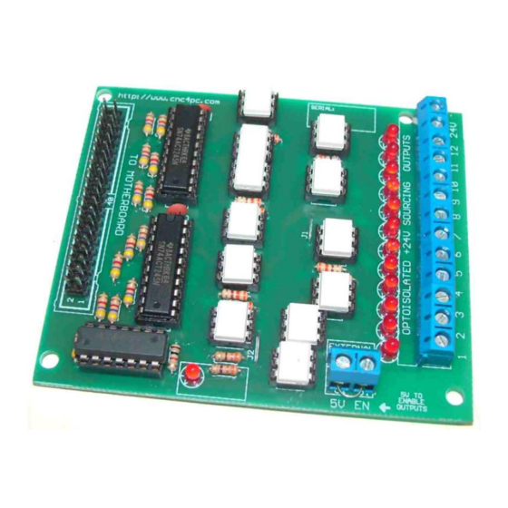
M28- 12OD(24)O EXPANSION BOARD
1. Overview
This board provides 12 optoisolated sourcing outputs for 24VDC signals.
2. Features
• 12 Optoisolated Sourcing 24V
Outputs.
• Darlington Outputs
• 24V Common Terminal.
• Screw-On connections for all
terminals. You only have to
screw-on the wires to make all
your connections.
Revision: 9/11/2009
Rev. 1.1
User manual Rev. 2
http://cnc4pc.com/TechDocs/M28R1_1_User_Manual.pdf
• Fully optoisolated.
• Support for up to 10 KHz
optoisolation.
• Status
LEDs
connections. No more guessing.
You can SEE all your signals.
• External Enable Pin (EN). The
board has a pin that allows you to
on
all output
1/8
Advertisement
Table of Contents

Related Manuals for CNC4PC M28


Summary of Contents for CNC4PC M28
- Page 1 M28(Rev. 1.1) User Manual M28- 12OD(24)O EXPANSION BOARD Rev. 1.1 User manual Rev. 2 1. Overview This board provides 12 optoisolated sourcing outputs for 24VDC signals. • Fully optoisolated. 2. Features • 12 Optoisolated Sourcing 24V Outputs. • Support for up to 10 KHz optoisolation.
- Page 2 M28(Rev. 1.1) User Manual enable/disable all the outputs at once. • Status outputs LED. 3. Specifications. DIGITAL OUTPUT SPECIFICATIONS Maximum output voltage Typical output current 100mA Maximum operation frequency 10KHz Time of transition to high impedance state 12 nS* *Time passed since a low in the ENABLE input is detected and the outputs are disabled.
- Page 3 M28 (Rev. 1.1) User Manual 4. Board description Power Requirements It requires a 24VDC @ 1.5 Amps external power supply to operate. WARNING Check the polarity and voltage of the external power source and connect the 24V .Overvoltage or reverse-polarity power applied to these terminals can cause damage to the board, and/or the power source.
- Page 4 M28 (Rev. 1.1) User Manual 5. Schematics 5.1 Discrete 24V sourcing Outputs Fig. 1 Outputs schematic Revision: 9/11/2009 http://cnc4pc.com/TechDocs/M28R1_1_User_Manual.pdf...
- Page 5 M28 (Rev. 1.1) User Manual 6. Wiring Diagrams Fig. 2 Wiring diagram to connect electromechanical relays. Revision: 9/11/2009 http://cnc4pc.com/TechDocs/M28R1_1_User_Manual.pdf...
- Page 6 M28 (Rev. 1.1) User Manual 7. Troubleshooting. SYMPTOM 1: THE BOARD DOES NOT REACT TO THE SIGNAL. POSSIBLE CAUSE POSSIBLE SOLUTIONS Pin conflict or mach3 configuration. Check that the pin you are using is not It is possible that the port address been used anywhere else in your setup.
- Page 7 M28 (Rev. 1.1) User Manual SYMPTOM 3: THERE IS NOISE IN THE SYSTEM. POSSIBLE CAUSE POSSIBLE SOLUTIONS The board could be underpowered. Make sure that main board can supply +5vdc@300mA to this board. There could be a short that could be Check that there are no hot spots in the board or it’s connections.
- Page 8 Arturo Duncan are not liable for any accidents resulting from the improper use of these devices. The M28 is not fail-safe device, and it should not be used in life support systems or in other devices where its failure or possible erratic operation could cause property damage, bodily injury or loss of life.
Need help?
Do you have a question about the M28 and is the answer not in the manual?
Questions and answers