Table of Contents
Advertisement
Quick Links
Advertisement
Table of Contents

Related Manuals for CNC4PC M26 - 12R


Summary of Contents for CNC4PC M26 - 12R
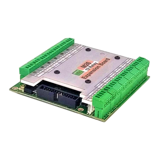
- Page 1 USER’S MANUAL VER. 1 M26 – 12R EXPANSION BOARD Rev. 5 APRIL 2021...
-
Page 2: Table Of Contents
USER'S MANUAL TABLE OF CONTENTS Contents Page# OVERVIEW ........................1 FEATURES ........................1 SPECIFICATIONS ......................2 BOARD DESCRIPTION ....................2 POWER TERMINAL ....................... 3 ENABLE TERMINAL ...................... 3 INPUT SIGNALS 10,11,12,13 AND 15 ................4 WIRING INPUT SIGNALS ....................4 PINOUT M26 ........................ -
Page 3: Overview
OVERVIEW This board provides 12 electromechanical relays with NO (Normally Open) and NC (Normally Closed) connections; this version can be easily mounted on control boxes using DIN rails and can also accommodate ribbon cables. FEATURES • 12 Electromechanical relays with NO and NC positions. •... -
Page 4: Specifications
SPECIFICATIONS ELECTROMECHANICAL RELAYS SPECIFICATIONS Maximum Current (AC) 7A@240VAC; 10A@125VAC Maximum Current (DC) 15A@24VDC; 10A@28VDC BOARD DESCRIPTION Requirements: It requires a 5VDC @ 0.5Amp external power supply to operate. WARNING User’s Manual Page 2... -
Page 5: Power Terminal
Check the polarity and voltage of the external power source and connect the 5V and GND. Overvoltage or reverse-polarity power applied to these terminals can cause damage to the board, and/or the power source. POWER TERMINAL ENABLE TERMINAL The card must be provided with a 5VDC signal to enable operation. This feature has been added to enable you to control externally the status of the relays of the card. -
Page 6: Input Signals 10,11,12,13 And 15
INPUT SIGNALS 10,11,12,13 AND 15 the input pin is activated with +5vdc. WIRING INPUT SIGNALS User’s Manual Page 4... - Page 7 -Wiring inputs using an external 24VDC power supply to keep input circuit isolated. Note: If using a +24vdc a 20K resistor is necessary to limit the voltage as the inputs can take only +5vdc. User’s Manual Page 5...
-
Page 8: Pinout M26
PINOUT M26 FUNCTION PINHEADER 26 PINS RELAY_1 RELAY_2 RELAY_3 RELAY_4 RELAY_5 RELAY_6 RELAY_7 RELAY_8 RELAY_9 RELAY_10 RELAY_11 RELAY_12 INPUT_10 INPUT_11 INPUT_12 INPUT_13 INPUT_15 ENABLE 19-25 User’s Manual Page 6... -
Page 9: 10.0 Dimensions
10.0 DIMENSIONS All dimensions are in Millimeters. Fixing holes (4mm) Disclaimer: Use caution. CNC machines can be dangerous machines. Neither DUNCAN USA, LLC nor Arturo Duncan is liable for any accidents resulting from the improper use of these devices. This product is not a fail-safe device and it should not be used in life support systems or in other devices where its failure or possible erratic operation could cause property damage, bodily injury or loss of life.
Need help?
Do you have a question about the M26 - 12R and is the answer not in the manual?
Questions and answers