Table of Contents
Advertisement
Quick Links
Advertisement
Table of Contents

Subscribe to Our Youtube Channel
Related Manuals for ATEQ VT47S


Summary of Contents for ATEQ VT47S
- Page 1 USER MANUAL VT47S www.ateq-tpms.com...
-
Page 2: Revision Of The User Manual
VT47S – User Manual REVISION OF THE USER MANUAL Due to continuing improvements, the information contained in this user manual, the features and design of this device are subject to be changed without prior notice. Edition/ Date Reference Chapters updated... -
Page 3: Table Of Contents
REVISION OF THE USER MANUAL ................1 INTRODUCTION ......................4 1. SPECIFICATIONS ..........................4 2. IMPORTANT SAFETY INSTRUCTIONS .................... 6 3. VT47S OVERVIEW ..........................8 3.1. Lights ............................8 3.2. Connectors ..........................8 4. FUNCTION KEYS ..........................9 5. POWER ON ............................9 6. - Page 4 VT47S – User Manual SETTINGS ........................29 1. SETTINGS MENU ..........................29 1.1. Change Units settings ....................... 30 1.2. Change Format settings ......................30 1.3. Change Buzzer On settings ...................... 31 1.4. Change Auto Off Settings ......................31 1.5. Change Zone settings ....................... 32 ABOUT ..........................
-
Page 5: Introduction
VT47S – User Manual INTRODUCTION 1. SPECIFICATIONS Power Supply 3.000 mAh rechargeable lithium-polymer battery Battery Life Approximately 300 activations per full charge Size (H x W x D) 174 mm x 97 mm x 36 mm (6.850 in x 3.818 in x 1.417 in) without rubber 176 mm x 109 mm x 43 mm (6.929 in x 4.291 in x 1.692 in) with... - Page 6 VT47S – User Manual Product content: Europe: 15 Rue des Dames 78340 Les Clayes s/Bois France Phone: +33 1 30 80 10 20 E-mail: emea-tpms@ateq.com Web: www.ateq-tpms.com Contact us: USA/Canada: 35990 Industrial Rd Livonia, MI 48150 Phone: 734-838-6119 E-mail: help@supporttpms.com Web: www.ateq-tpms.com...
-
Page 7: Important Safety Instructions
VT47S – User Manual 2. IMPORTANT SAFETY INSTRUCTIONS Do not discard. Retain for future reference. Please note that changes or modifications not expressly approved by the party responsible for compliance could void the user’s authority to operate the equipment. Note: This equipment has been tested and found to comply with the limits for a Class B digital device, pursuant to part 15 of the FCC Rules. - Page 8 VT47S – User Manual WARNING: This product emits electromagnetic and electronically generated waves that may interfere with the safe operation of pacemakers. Individuals that have pacemakers should never use this product. Read the Warranty, Safety, FCC Statements and recycling information at the end of this user manual.
-
Page 9: Vt47S Overview
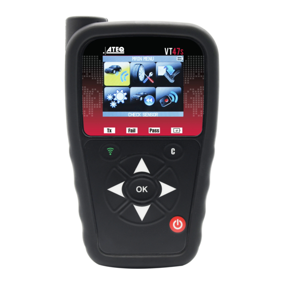
VT47S – User Manual 3. VT47S OVERVIEW LF/RF Antenna Battery charge/low Display screen battery indicator Result indicators Cancel/No Transmission indicator Trigger button OK/Confirmation button Navigation buttons Power ON/OFF button 3.1. L IGHTS Result light Result light Trigger light Battery status "Fail"... -
Page 10: Function Keys
VT47S – User Manual 4. FUNCTION KEYS Power ON/OFF switch Test or trigger sensor Next, continue or confirm Cancel, previous step Navigate to select "up” Navigate to select “down” Navigate to select “left” Navigate to select “right” 5. POWER ON... -
Page 11: Service Procedure
VT47S – User Manual 6. SERVICE PROCEDURE Follow this TPMS service procedure each time before and after servicing tires/wheels. 6.1. T EST SENSORS Following the instructions in the CHECK TPMS menu of your TPMS TOOL. Trigger each of the vehicle’s sensors, to ensure they work properly. -
Page 12: Troubleshooting
VT47S – User Manual 6.4. T ROUBLESHOOTING If the TPMS TOOL is unable to trigger one or more of the sensors, please use the following troubleshooting guide: 1) The sensor itself may be damaged or defective. 3) Wrong make, model, year is selected. -
Page 13: Tpms Tool Usage
VT47S – User Manual TPMS TOOL USAGE IMPORTANT: Vehicle specific information in this manual is used as an example and may not represent specific instructions each make and model may require. When performing various functions with the tool, it is important to refer to the on-screen prompts and/or repair manual information. -
Page 14: Select Year
VT47S – User Manual 1.3. S ELECT YEAR 1.4. S ELECT NUMBER OF WHEELS AND SELECT TIRE This option does not appear for all vehicles. For example, this option is = continue used for vehicles with a TPMS sensor fitted on the spare wheel. -
Page 15: Test Sensors
VT47S – User Manual 1.5. T ENSORS Left Front Press this button to read the sensor and press OK or use the arrow buttons to select next tire to read. Right Front Right Rear Left Rear Spare Wheel Trigger if the car is... -
Page 16: Service Tpms
VT47S – User Manual 1.6. S TPMS ERVICE This menu has two main functions. One is to relearn the ID of the 4 sensors into the ECU. The other function aims at reading the spare part for all the sensors available by vehicle. -
Page 17: Reprogram Ecu Through Obd-Ii Port
VT47S – User Manual 1.8. R OBD-II P EPROGRAM THROUGH Read all the sensors Plug OBD2 cable to the tool and to the vehicle. Note: this following screen message is displayed when all the sensors are triggered and the OBD2 cable is connected to the TPMS TOOL. -
Page 18: Part # Lookup
VT47S – User Manual The data is successfully transferred to the ECU. The OBD2 cable can be unplugged from the ECU to the tool. 2. PART # LOOKUP This is a spare parts database which indicates all the sensors references available for each car. -
Page 19: Program Universal Sensor
VT47S – User Manual 3. PROGRAM UNIVERSAL SENSOR Select the "PROGRAM SENSOR" function. = continue This section explains how to get a sensor ID in order to enter it in a universal sensor. If the "old" sensor can be read, use the COPY ORIGINAL SENSOR section to recover the ID. If it cannot be read, use the CREATE NEW SENSOR section to create a new ID. -
Page 20: Copy Id Function
VT47S – User Manual 3.1. C FUNCTION = continue Use the keyboard to select “COPY ID” function. Press to trigger the original sensor Wait a few seconds. The ID of the old sensor is displayed. = continue Page 19/41... - Page 21 VT47S – User Manual Hold the new programmable sensor Please wait near the device antenna. during the programming Press to upload process. data to the blank sensor The data has been successfully transferred to the sensor. Page 20/41...
-
Page 22: Create New Sensor Function
VT47S – User Manual 3.2. C REATE NEW SENSOR FUNCTION = continue Use the keyboard to select “CREATE NEW SENSOR” function Hold the new *It is also programmable sensor possible to near the device antenna. overwrite a programmable Press to upload sensor already used. -
Page 23: Copy Set Of Sensors Function
VT47S – User Manual 3.1. C OPY SET OF SENSORS FUNCTION = continue Use the keyboard to select “COPY SET OF SENSORS” function Press to read the first sensor. Read all the sensors. Finish by pressing Use the keyboard to select the next wheel. -
Page 24: Retrieve Id Function
VT47S – User Manual Wait a few seconds. Press The data has been successfully uploaded to the sensor. to continue. Press to program the Use the keyboard to select next sensor. the next wheel. 3.2. R ETRIEVE FUNCTION = continue Use the keyboard to select “RETRIEVE ID”... - Page 25 VT47S – User Manual Plug OBD2 cable to the tool and to the vehicle. Press when you are ready. You are ready to program the first sensor with the actual ID from the car. = continue Wait until the Press process is finished.
- Page 26 VT47S – User Manual Press The data is successfully uploaded to the sensor. to program the next sensor. Page 25/41...
-
Page 27: Recent Sensor Data
VT47S – User Manual RECENT SENSOR DATA 1. RECENT SENSOR DATA When a new vehicle is triggered the result is automatically stored in the RECENT SENSOR DATA menu. You may recall the result and continue to trigger the entire vehicle. The data is automatically replaced if a new vehicle is triggered. -
Page 28: Rke Test
VT47S – User Manual RKE TEST 1. RKE TEST This is to test the strength of the keyfob RF signal. = continue Select "RKE TEST" function. = previous 1.1. S ELECT ANUFACTURER = continue = previous 1.2. S ELECT REQUENCY... -
Page 29: Read Instructions
VT47S – User Manual 1.3. R EAD INSTRUCTIONS To start a new test. Press and hold one of the keyfob buttons. = previous è The device waits for RF signal. 1.4. T EST RESULTS PASS: High signal strength, green range. -
Page 30: Settings
VT47S – User Manual SETTINGS 1. SETTINGS MENU Select "SETTINGS" menu. = continue = continue Scroll up and down to select function or settings, = previous press OK to select. Key functional descriptions: REGION: to select the area of work, AMERICA, EUROPE UNITS: change the air pressure and temperature display (kPa, Bar or PSI with F°... -
Page 31: Change Units Settings
VT47S – User Manual 1.1. C HANGE NITS SETTINGS = continue Scroll up and down to = previous select function or settings. = continue Scroll up and down to = previous select the units. 1.2. C HANGE ORMAT SETTINGS = continue... -
Page 32: Change Buzzer On Settings
VT47S – User Manual AUTO: display sensor ID format in the way sensor is transmitting. DECIMAL: force to display sensor ID in decimal (0 to 9). HEXADECIMAL: force to display sensor ID in hexadecimal (0 to F). NOTE: Some OE sensors manufacturers print sensor ID at housing in decimal format. In this case, you can easily set your tool to display IDs in decimal format to verify the reading done with the TPMS tool. -
Page 33: Change Zone Settings
VT47S – User Manual The selection turns red. = continue Scroll up and down to set Change from 60 min (maximum) to DISABLED (never). 1.5. C HANGE ONE SETTINGS Scroll up and down to select the zone menu. continue Scroll up and down to select a zone. -
Page 34: About
VT47S – User Manual ABOUT 1. ABOUT MENU This menu displays the current version and information about the device. Select the "ABOUT" menu. = continue Page 33/41... -
Page 35: Language
VT47S – User Manual LANGUAGE 1. LANGUAGE MENU Select the "LANGUAGE" menu. = continue Scroll up and down to select the language. The tool will load the new selected language. Page 34/41... -
Page 36: Miscellaneous
VT47S – User Manual MISCELLANEOUS 1. CHARGE Low Battery Indication Battery indicator status: Your TPMS TOOL incorporates a low battery detection circuit. Battery life is an average of 300 sensor tests per battery 100% charge (approximately 60 to 80 vehicles) -
Page 37: Tool Update
VT47S – User Manual 2. TOOL UPDATE Updating the TPMS TOOL When a new protocol becomes available, it is necessary to update your tool. Please follow the steps below: IMPORTANT: Temporarily turn off all anti-virus and spam blocking software on your computer. -
Page 38: Limited Hardware Warranty
VT47S – User Manual http://www.ateq-tpms.com/ 3. LIMITED HARDWARE WARRANTY Limitation of Liability ATEQ Limited Hardware Warranty ATEQ SHALL NOT BE LIABLE FOR ANY ATEQ warrants to the original purchaser that SPECIAL, INDIRECT, INCIDENTAL ATEQ your hardware product shall be free... - Page 39 The Lithium-polymer battery is not suitable for object. children under 14 years. Keep all Lithium-Ion batteries out of the reach of children Use a specified charger approved by the ATEQ manufacturer and supplied with the To prevent leakage or other hazards, do not Page 38/41...
-
Page 40: Manufacturer
VT47S – User Manual store batteries above 60°C (140°F). Never and used in accordance with the instructions, leave the battery inside a car (for example) may cause harmful interference to radio where the temperature could be very high or in communications. -
Page 41: Ce Statements
VT47S – User Manual 7. CE STATEMENTS DECLARATION OF CONFORMITY The manufacturer of the TPMS TOOL declares that this device complies with the requirements of: - ETSI EN 300 330-1 V1.8.1 (2015-03): Electromagnetic compatibility and Radio spectrum Matters (ERM); Short Range Devices (SRD); Radio equipment in the frequency range 9 kHz to 25 MHz and inductive loop systems in the frequency range 9 kHz to 30 MHz;... - Page 42 VT47S – User Manual EU Declaration of Conformity (DoC) Company name : ATEQ Postal address : 15 rue des Dames Postcode and City : 78340 Les Clayes sous Bois Telephone number : 01 30 80 10 20 E-Mail address : info@ateq.com...
-
Page 43: Index
VT47S – User Manual INDEX About ........... 33 Part lookup ......... 17 Auto off ..........32 Power supply ........38 Battery ..........38 Recent sensor data ......26 Buzzer ..........31 Recycling ........39, 40 Retrieve ID ......... 24 Caution ..........7, 38 RKE Test ........ - Page 44 This document is the exclusive property of ATEQ. It may not be communicated, reproduced or used without prior consent.
Need help?
Do you have a question about the VT47S and is the answer not in the manual?
Questions and answers