Table of Contents
Advertisement
Advertisement
Table of Contents

Subscribe to Our Youtube Channel
Related Manuals for ATEQ D520


Summary of Contents for ATEQ D520
- Page 1 USER MANUAL ATEQ D520 Version 1.32 Reference: UM-22100H-U...
- Page 3 REVISION OF THE D520 USER MANUAL Due to continuing improvements, the information contained in this user manual, the features and design of this device are subject to be changed without prior notice. Edition/ Date Reference Chapters updated Revision (week/year) First edition...
- Page 5 • do not open the instrument when it is powered up, • avoid water spillage near of the instrument, • ATEQ is at your disposal for any further information concerning the use of the instrument under maximum safety conditions. We would like to bring to your attention that ATEQ will not be held responsible for any accident connected to the improper use of the instrument, to the work bench or to the lack of compliance with safety rules.
- Page 7 ATEQ is attached to the COFRAC and delivers a certificate following a calibration. TRAINING COURSES In the framework of partnership with our customers, ATEQ offers two types of training in order to optimise the usage and knowledge of our instruments. They are aimed at different levels of technician: •...
- Page 9 PREFACE Dear Customer, You have just purchased an ATEQ instrument, we thank you for the trust you have placed on our brand. This instrument has been designed to ensure a long and unparalleled life expectancy, and we are convinced that it will give you complete satisfaction during many long years of operation.
-
Page 11: Table Of Contents
Chapter 1 INSTALLATION OF THE INSTRUMENT 1. PRESENTATION OF THE ATEQ D520 ....................15 2. INSTALLATION OF THE INSTRUMENT ..................16 2.1. Presentation of the connectors on the case of the D520............16 2.2. Connector details ........................17 Chapter 2 USER INTERFACES 1. PRESENTATION OF THE FRONT PANEL OF THE D520 ..............27 2. - Page 12 2.3. Automatic connectors with expandable joints ................104 2.4. Filtration kit ..........................104 2.5. Remote controls ........................105 2.6. Remote front panel RC5 ......................106 2.7. Intelligent remote control......................108 2.8. External cutting valve .......................110 Chapter 6 ERROR MESSAGES ERROR MESSAGES ....................111 UM-22100H-U User manual ATEQ D520 Page 2/122...
- Page 13 1.6. Calibration ..........................114 1.7. Concerns about reliability of the instrument’s circuits ..............114 Appendices ATEQ D520 1. TECHNICAL CHARACTERISTICS OF THE D520 .................115 2. DIMENSIONS OF THE D520......................116 3. CONVERSION TABLE ........................117 4. PARAMETERS SAVED........................118 5. VALVE CODES USED IN YOUR APPLICATION ................119 6.
- Page 14 Table of contents UM-22100H-U User manual ATEQ D520 Page 4/122...
-
Page 15: Preamble
Preamble PREAMBLE 1. DEFINITION OF THE ATEQ D520 The ATEQ D520 is a flow meter which measures a drop in pressure with a differential sensor (transducer) which is placed at the extremities of a calibrated flow tube. Absolute pressure sensor... -
Page 16: Characteristcs Of The Measurement
- 600 kPa to -10 kPa / 800 Pa to 6 kPa / 500 Pa to 14 kPa / 6 kPa to 100 kPa / 5 kPa to 210 kPa / 10 kPa to 350 kPa. UM-22100H-U User manual ATEQ D520 Page 6/122... -
Page 17: The Different Measurement Principles
As shown in the diagram above the test pressure is applied directly to the test part input after having flowed through the calibrated flow tube. Once the test part is filled, the ATEQ D520 measures the drop in pressure at the extremities of the calibrated flow tube with a differential sensor. -
Page 18: Indirect Measurement (Or Recovery Mode)
The indirect measurement allows a considerable gain in time as the flow which arrives in the calibrated flow tube is already stabilised. UM-22100H-U User manual ATEQ D520 Page 8/122... -
Page 19: Pressure, Temperature & Viscosity Effect On The Measurement
The results are always expressed as a function of the test pressure. That is why a silicium sensor constantly monitors the real test pressure applied to the part. Depending on the pressure value read the ATEQ D520 applies a correction factor which allows a constant compensation for the pressure drops in the test circuit. -
Page 20: Calibration
In this case a manual calibration taking into account the previously stated elements, can be carried out by the operator. For this calibration, the calibrated master leak should be used in the same conditions as the parts to be measured (diameter, length of the pipes). UM-22100H-U User manual ATEQ D520 Page 10/122... -
Page 21: Principle Of A Cycle
Parameter to be set. End of The instrument stops the measurement and sends an end of cycle Cycle signal. UM-22100H-U User manual ATEQ D520 Page 11/122... -
Page 22: Presentation Of The Symbols
Connector Connector for pneumatic input. Read and respect the instructions of the user manual, Warning! before plugging and using the instrument. Remote Connector for a remote control. control Printer Connector for printer plugging. UM-22100H-U User manual ATEQ D520 Page 12/122... - Page 23 Dry contact output. Input Dry contact input. Infrared link, at this place there's the receiver and Infrared link transmitter of the infrared link. Analogue Analogue output. output Analogue Analogue input for the temperature sensor. input UM-22100H-U User manual ATEQ D520 Page 13/122...
- Page 24 Preamble UM-22100H-U User manual ATEQ D520 Page 14/122...
-
Page 25: Chapter 1 Installation Of The Instrument
> D520 The ATEQ D520 is presented in a painted and formed metal case which rests on four rubber feet. The upper cover is linked to the structure with 2 screws. The format of the case has been reduced to allow easy insertion of the instrument. -
Page 26: Installation Of The Instrument
► I1 I2 I3 ► I4 I5 I6 I7 ►O1 O2 O3 O4 O5 ► 200 mA 24 V === 24 V === SERVICE RS485 ENTREE/IN RS485 SORTIE/OUT TEST RS232 MADE BY ATEQ www.ateq.com UM-22100H-U User manual ATEQ D520 Page 16/122... -
Page 27: Connector Details
2.2. C ONNECTOR DETAILS 2.2.1. Electrical connectors The ATEQ D520 operates under a power of 24V DC with either : the transformer delivered with the instrument, or through the network cable when the instrument is a slave. 2.2.1. 1) J1 connector (Output codes / Analogue outputs /... - Page 28 (one or more at a time). Binary weighting n + 1. Combinations of the pins to be activated to select the programs Program Pin 5 Pin 6 Pin 7 Pin 8 number (input 3) (input 4) (input 5) (input 6) UM-22100H-U User manual ATEQ D520 Page 18/122...
- Page 29 Regulator adjustment request, Infinite fill request, Piezo reset request, Manual differential reset request, Calibration learning request, Calibration check request, ATR learning request, Reference adjustment request. Some possibilities only appear if the function is used. UM-22100H-U User manual ATEQ D520 Page 19/122...
- Page 30 Note: The 24V power supply must be provided by the internal power supply of the ATEQ instrument (0,3A maximum) OR through an external power supply provided by the customer. In the case of customer external supply, the ATEQ instrument can be supply by the 2 and 4 pins on the J3 connector too. UM-22100H-U...
- Page 31 J3 connector too. (Programmable input) Common 0,2 A Good part 0,3 A Max Test fail part with ATEQ 24 V DC Reference fail part Alarm 0,2 A End of cycle Ground UM-22100H-U User manual ATEQ D520 Page 21/122...
- Page 32 Network (RXD) PIN 2 Power + 24V PIN 4 Ground 0V 2.2.1. 9) J6 input connector (RS485) ATEQ only network. Allows the connection to other ATEQ instruments. (Male Lumberg type connector). PIN 1 Network (D+) PIN 3 Network (D-) PIN 2...
- Page 33 2.2.2. Pneumatic connectors For the ATEQ D520, the automatic connectors can be installed on the front panel or on the rear panel depending on the option chosen. These pneumatic outputs can take on different functionalities depending on the configuration requested following the purchase of the instrument (stamping, cut off, dump, second test output, etc.).
- Page 34 ► I1 I2 I3 ► I4 I5 I6 I7 ►O1 O2 O3 O4 O5 ► 200 mA 24 V === 24 V === Pressure SERVICE RS485 ENTREE/IN GAS EXIT T° RS485 TEST GAS INPUT SORTIE/OUT TEST (DIR.) RS232 (IND.) MADE BY ATEQ www.ateq.com UM-22100H-U User manual ATEQ D520 Page 24/122...
- Page 35 For this purpose it is highly recommended that an appropriate leak proof filter is fitted between the test part and the instrument. This filter can be supplied by ATEQ. The presence of impurities, oil or humidity in the air may cause a deterioration for which the guarantee will not be valid.
- Page 36 Chapter 1 – Installation of the instrument UM-22100H-U User manual ATEQ D520 Page 26/122...
-
Page 37: Chapter 2 User Interfaces
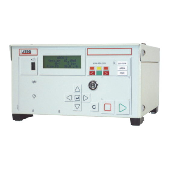
Chapter 2 – User interfaces Chapter 2 USER INTERFACES 1. PRESENTATION OF THE FRONT PANEL OF THE D520 Results 4 lines LCD Key lock indicators display www.ateq.com < > D520 Pressure Navigation regulator Cycle keys Quick keys connectors UM-22100H-U User manual ATEQ D520 Page 27/122... -
Page 38: Presentation Of The Keyboard Keys
Not used Not used ENTER key Enter the Parameter edition menu Validation of a parameter « C » for CANCEL Return to the previous menu or function Escape a parameter without modifying it UM-22100H-U User manual ATEQ D520 Page 28/122... -
Page 39: Cycle Keys
The access to the adjustable parameters is not possible. ACCESS position. Access to the adjustable parameters. Note: whatever the position of the key-lock is (LOCKED or ACCESS), it is possible to start and stop test cycles. UM-22100H-U User manual ATEQ D520 Page 29/122... -
Page 40: Regulator
It allows the easy checking of the pressure. It is used for the regulator circuit. It allows the checking of the test pressure displayed by the instrument with a precision manometer or the ATEQ Leak/Flow calibrator. UM-22100H-U User manual ATEQ D520 Page 30/122... -
Page 41: Functionnality Of The Indicators
Fail large flow indicator (flow too big). < > Fail low flow indicator (flow too weak). < > Warning. < > Standby, (intermittent flashing). < > Recoverable parts (indicator constantly lit). < > UM-22100H-U User manual ATEQ D520 Page 31/122... - Page 42 Chapter 2 – User interfaces UM-22100H-U User manual ATEQ D520 Page 32/122...
-
Page 43: Chapter 3 Startup And Adjustments
Chapter 3 – Start-up and adjustments Chapter 3 STARTUP AND ADJUSTMENTS 1. POWERING UP THE ATEQ D520 Supply the instrument with 24 V DC. When switched on the instrument : ATEQ D5 displays the version and the Version XX.XXi 0->... -
Page 44: Creation Of A Test Program
2.1. C HOICE OF THE PROGRAM NUMBER PARAMETERS Position the cursor in front of Copy-Paste the chosen program number. Pr :01 ---------- Confirm with the ENTER key. Pr :02 ---------- UM-22100H-U User manual ATEQ D520 Page 34/122... -
Page 45: Selection Of The Test Type
This test type allows the operator to carry out actions (or checks) on the part undergoing a test then to confirm them with the "START" key if the test is considered to be good, or on the "RESET" key if the test is considered to be bad. UM-22100H-U User manual ATEQ D520 Page 35/122... -
Page 46: Adjustment Of The Parameters
To move to the next TYPE : DIRECT FLOW parameter, use the navigation COUPL. A : 03.00 s keys. FILL : 00.00 s PARAMETERS To exit the menu, use the Copy-Paste Pr:001 FLOW CANCEL key. Pr:002 FLOW UM-22100H-U User manual ATEQ D520 Page 36/122... - Page 47 Adjust this parameter according to the method described in § 2.3. 2.3.5. Pressure unit The different units are: bar, mbar, PSI, Pa, kPa, MPa. Adjust this parameter according to the method described in § 2.3. UM-22100H-U User manual ATEQ D520 Page 37/122...
- Page 48 This parameter allows the definition of the lower limit of the authorised flow range in the test part, under this limit the part is considered as bad. Adjust this parameter according to the method described in § 2.3. UM-22100H-U User manual ATEQ D520 Page 38/122...
- Page 49 Chapter 3 – Start-up and adjustments 2.3.11. Range (second capillary option) The second capillary is an option on the D520 instrument, it allows having two flow measurement ranges so that to have best adapt of the measurement extend of the capillary in function of the part to be controlled.
-
Page 50: Copying A Test Program
Attribute a number to this new COPY :Pr 001 program by using the PASTE :Pr 003 navigation keys (for example n°3). Confirm with the ENTER key. COPY IN PROGRESS... The display confirms the copy of the program. UM-22100H-U User manual ATEQ D520 Page 40/122... - Page 51 PASTE :Pr 003 this example, program n°3 is therefore an exact copy of program n°1. MAIN MENU Press twice on CANCEL to RUN PROG PARAMETERS return to the main menu. SPE CYCLE :Disabled UM-22100H-U User manual ATEQ D520 Page 41/122...
-
Page 52: Deleting A Program Or The Name Of A Program
Confirm with ENTER. The program is deleted. PARAM/Pr001 TEST : PRESS. CYCLE Note: if the "Delete a COUPL. A : 00.0 s program" operation is done INIT.PRES: 0000 first, then the program name is also deleted. UM-22100H-U User manual ATEQ D520 Page 42/122... -
Page 53: Launching Of A Cycle
RUN PROG. : 004 PARAMETERS through the numbers with the SPE CYCLE :Disabled navigation keys. MAIN MENU Confirm your choice with the RUN PROG. : 004 PARAMETERS ENTER key. SPE CYCLE :Disabled UM-22100H-U User manual ATEQ D520 Page 43/122... -
Page 54: Setting The Test Pressure
To input a fill instruction, refer to the previous paragraph. Reminder: the input pressure with an instrument fitted with an electronic regulator must be at least superior by 100 kPa (1 bar) of the test pressure. UM-22100H-U User manual ATEQ D520 Page 44/122... -
Page 55: Starting A Measurement Cycle
TEST. 7. STOPPING A CYCLE Press the RESET key to stop RUN/Pr:004 the measurement. The display PRESS =0.500 bar “READY” indicates that the instrument is ready to perform READY a new measurement test. UM-22100H-U User manual ATEQ D520 Page 45/122... - Page 56 Chapter 3 – Start-up and adjustments UM-22100H-U User manual ATEQ D520 Page 46/122...
-
Page 57: Menu Structure
> ml/mn > ml/h Reject unit > USA : in /h > ft > in /mn > in /h > /h > in Maximum reject Minimum reject Functions > Refer to note UM-22100H-U User manual ATEQ D520 Page 47/122... - Page 58 Refer to note SPECIAL CYCLES > Disabled Electronic regulator learning Regulator adjustment Infinite fill CAL learning CAL check ATR learning Atmospheric conditions Reference calibration Piezo auto zero CONFIGURATION > Extended menus > Name Cycling UM-22100H-U User manual ATEQ D520 Page 48/122...
- Page 59 30 % > 50 % > Bar graph > yes / no > 70 % > Cal reference > Yes/no Regulator > yes / no > Frequency learning Number of cycles Output > configuration reference External 3 UM-22100H-U User manual ATEQ D520 Page 49/122...
- Page 60 8bit-="1" > 1 8bit-even > 1 8bit-odd > Frame > Pressure Personalization Time keeper Before results After results Line feed Sending > conditions Part OK Maximum part Minimum part Warning Pressure error Recoverable UM-22100H-U User manual ATEQ D520 Page 50/122...
- Page 61 Piezo auto zero Manual differential reset SERVICE > PARAMETERS > Save Recover Delete SENSOR > Pressure Leak RESULTS > Program Statistics > Program Total Part OK Maximum part Minimum part Recoverable Warning Reset Print UM-22100H-U User manual ATEQ D520 Page 51/122...
-
Page 62: Functions" Menu When Activated
SI: ml/h > l/s > ml/s > ml/min > ml/h. USA: in /h > Reject unit /h > in /min > /h > ft /h > /min Drift CAL Name Single CAL > Yes/No Delete CAL name UM-22100H-U User manual ATEQ D520 Page 52/122... - Page 63 P1 – P2 min. Correction > Instruction P1 – P2 Fill mode > Standard Instruction > Fill instruction Ballistic Auto connector > Coupling A Coupling B Valves codes > Stamping Dump External 3 UM-22100H-U User manual ATEQ D520 Page 53/122...
- Page 64 Full scale flow Butane > Viscosity % / degree C Full scale flow Natural gas > Viscosity % / degree C Full scale flow Nitrogen > Viscosity % / degree C Full scale flow UM-22100H-U User manual ATEQ D520 Page 54/122...
-
Page 65: Configuration Menu
Restart the operation if necessary to activate other functions. Once all the chosen functions MAIN MENU have been activated, press SPE CYCLE: Disabled CONFIGURATION twice on the CANCEL key to RESULTS return to the main menu. UM-22100H-U User manual ATEQ D520 Page 55/122... - Page 66 Manually, the instrument shift to the reference circuit with the operator request, or automatic. Selection by the front panel or the inputs/outputs of the concerned program. Automatically the instrument shift to the reference circuit before each test cycle. UM-22100H-U User manual ATEQ D520 Page 56/122...
- Page 67 Therefore the results of the measurements will not take into account the ambient variations. To confirm this function, an asterisk is displayed after "FLOW". Select the option and adjust settings if necessary. UM-22100H-U User manual ATEQ D520 Page 57/122...
- Page 68 Select the option and adjust settings if necessary. 2.1.3. 9) Pressure reset The reset cycle in an ATEQ D520 instrument is carried out for each test cycle. This function allows the positioning of the auto zero (reset) in the test cycle. The positioning...
- Page 69 PARTS PARTS PARTS REF REJECT TEST REJET RECOVERABLE LEVEL RECOVERABLE LEVEL Example FROM 0 TO 10 THE PARTS ARE GOOD FROM 10 TO 20 THE PARTS ARE RECOVERABLE OVER 20THE PARTS ARE BAD UM-22100H-U User manual ATEQ D520 Page 59/122...
- Page 70 Never the less, to move into stabilization, the test pressure must be between the thresholds at the end of the fill. UM-22100H-U User manual ATEQ D520 Page 60/122...
- Page 71 (see Chapter 1 paragraph 2.2.1.1.). Associated parameters to be set: External 1, External 2, External 3, External 4, External 5, External 6, Internal 1, Internal 2. Select the option and adjust settings if necessary. UM-22100H-U User manual ATEQ D520 Page 61/122...
- Page 72 ), and has a base time of 0.01 s instead of 0.1 s. Programming for the ATEQ D520 mini valve is identical to that for the standard ATEQ D520. Associated parameters to be set: A-Z Diff (Differential Auto-zero). This time can be reduced as long as the values obtained are stable and repeatable.
- Page 73 Then select the inking MAINTAIN : 00.5 s : Non conditions from those offered. : Oui When the instrument possesses this option, the internal and external valve codes 1 are no longer available. UM-22100H-U User manual ATEQ D520 Page 63/122...
- Page 74 (connection to a PLC or robot…). a) Relay sequencing depending the End of Cycle In order to interface the ATEQ D520 with its environment (PLC, PC …), the timing charts below give the sequence for the electrical outputs (relay board on J8 connector) and pneumatics (automatic connectors) according to the commands entered on the front panel or on the J8 connector (START, RESET).
- Page 75 This selection can only be modified during the inter cycle period. To return to program 1, when a cycle is not in progress, press any of the program selection inputs. UM-22100H-U User manual ATEQ D520 Page 65/122...
- Page 76 This selection can only be modified during the inter cycle period. To return to program 1, when a cycle is not in progress, press any of the program selection inputs. UM-22100H-U User manual ATEQ D520 Page 66/122...
- Page 77 This selection can only be modified during the inter cycle period. To return to program 1, when a cycle is not in progress, press any of the program selection inputs. UM-22100H-U User manual ATEQ D520 Page 67/122...
- Page 78 (or after the coupling time B if it is present). PRESSURE t mini START t mini RESET Program t mini N° Active Auto Time B connector A Disabled Active Auto Time B connector B Disabled part End of Cycle UM-22100H-U User manual ATEQ D520 Page 68/122...
- Page 79 This type of instrument has a specific hardware configuration, a connection allows the rejection of a small quantity of gas at each piezo auto reset. The precautions related to the use of a flammable gas are to be applied to the working station. UM-22100H-U User manual ATEQ D520 Page 69/122...
- Page 80 Then select the "PERCENT" >FILL MODE : PERCENT mode in the "FILL MODE" function. Connect a pass part to the instrument and make the flow instruction adjustment by starting the "Elec Reg Adjust" special cycle. UM-22100H-U User manual ATEQ D520 Page 70/122...
- Page 81 Note: it's possible to modify manually the flow thresholds calculated by the instrument. The flow instruction taken in account for the test cycles will be the average of the maximum and the minimum thresholds. UM-22100H-U User manual ATEQ D520 Page 71/122...
-
Page 82: Automatic Save
ACCESS to the LOCKED position. This function is useful if the parameters in the RAM are accidentally erased. The instrument will then automatically read and restore the flash parameters in the RAM. UM-22100H-U User manual ATEQ D520 Page 72/122... -
Page 83: Program Sequences
Sequence 03 > Sequence 32 Program 1 Program 3 Program 1 Program 4 Program 3 Program 2 Program 7 Program 1 Program 1 Program 2 Program 1 Program 4 Program 2 Program 3 UM-22100H-U User manual ATEQ D520 Page 73/122... - Page 84 PRESS = 30.0 mbar pressing the START CYCLE key. READY Note: if the sequence doesn't start or if it stops on a program test, check in this program if the function and cycling conditions are validated. UM-22100H-U User manual ATEQ D520 Page 74/122...
- Page 85 "UTILITY" menu SQ01 then validate. SQ02 The select the desired SEQUE/UTILITY command, the procedures are COPY : ---------- the same as the test PASTE : ---------- parameters program DELETE NAME : SQ01 management. UM-22100H-U User manual ATEQ D520 Page 75/122...
-
Page 86: Ready Status
30 %, 50 % or 70 % of the bar graph. The example below represents a bar graph with a maximum threshold at 50 %: Flow value Representation of the thresholds Select the option and adjust settings if necessary. UM-22100H-U User manual ATEQ D520 Page 76/122... -
Page 87: Hour
This function allows making a correction of the pressure instruction according the flow. When this correction is too important, an alarm "< Min. Pressure" is activated. During the stabilization and test phases, no instruction correction is realized. UM-22100H-U User manual ATEQ D520 Page 77/122... -
Page 88: Rs232
Personalization (Display of the program name when there is one), Timekeeper (printing of the date and the time), Before result (number of lines before the result), After result (number of lines after the result), Inter Line (space between each line). UM-22100H-U User manual ATEQ D520 Page 78/122... - Page 89 : P R E S S U R E L O W < 0 1 > : ( A L ) : P R E S S U R E H I G H UM-22100H-U User manual ATEQ D520 Page 79/122...
- Page 90 This frame is operated by connecting a computer to the instrument's RS232 link. Select the option and enter settings if necessary. 2.9.5. Print the parameters By validating this function, the test parameters of the programs activated on the instrument are instantly printed. UM-22100H-U User manual ATEQ D520 Page 80/122...
-
Page 91: Rs485
2.12. S ECURITY This function deactivates the START key on the instrument front panel. Programs can only be started from the instrument inputs (J3 connector). Select the option and enter settings if necessary. UM-22100H-U User manual ATEQ D520 Page 81/122... -
Page 92: Lighting The Screen
INTENSITY menu and confirm using ENTER. Then select the lighting MAIN/CONFI/LIGHT intensity from 00 (off) to 07 MODE :CONT (maximum) and the new INTENSITY: 04 lighting intensity will be applied after ENTER is pressed. UM-22100H-U User manual ATEQ D520 Page 82/122... -
Page 93: Bar Code Option
The quantity of characters read by the reader should not exceed 22. Beyond the unit will not take into account the character string (bar code string). This option is valid for the units starting from the last version ATEQ devices. 2.14.2. Communication parameters configuration... - Page 94 E F G H I J K L M N. Number total of characters = 22 If a same characters string is on several programs, the program with the smallest number will be selected the others will be ignored. UM-22100H-U User manual ATEQ D520 Page 84/122...
- Page 95 The code is recorded and the CYCLE/Pr : 01 device is ready to run. At each PRESS = 185.8 mbar time this character string is 123456789001XXXXXXXX flashed, the paired program READY (OK) will be set as active program. UM-22100H-U User manual ATEQ D520 Page 85/122...
-
Page 96: I/Oconfiguration
See the Chapter 1, paragraph 2.2.1.5) "Connector J3 (Inputs/Outputs) programmable input". Note: the manual auto zero maintains the instrument in auto zero mode as long as the input is not activated. UM-22100H-U User manual ATEQ D520 Page 86/122... -
Page 97: Remote Control
The special cycle appears and is programmable if it has been activated in at least one of the test programs. The programmed special cycle appears on the same key for all the programs, it will be inactive if it is disabled in the current program. UM-22100H-U User manual ATEQ D520 Page 87/122... -
Page 98: Special Cycles Menu
(the temperature is taken inside the instrument). To run a special cycle, select it in the "special cycles" menu, then press the button. To stop it, press the button. In some cycles the stop is automatic. UM-22100H-U User manual ATEQ D520 Page 88/122... -
Page 99: Regulator
PRESS = 500.0 mbar using the UP and DOWN REGULATOR ADJUST keys. CYCLE/Pr :001 Once the pressure is adjusted, PRESS = 0.000 bar press the RESET key to stop the special cycle. READY UM-22100H-U User manual ATEQ D520 Page 89/122... -
Page 100: Calculation Of The Automatic Thresholds
Note: in the event of vacuum tests, the negative pressure thresholds keep their mathematical "order". PRESSURE MEASUREMENT MAXIMUM REJECT PRE-FILL MINIMUM REJECT LEVEL THRESHOLD LEVEL VACUUM MEASUREMENT MAXIMUM MINIMUM PRE-FILL REJECT LEVEL REJECT LEVEL THRESHOLD UM-22100H-U User manual ATEQ D520 Page 90/122... -
Page 101: Infinite Fill
FILL CYCLE/Pr:001 Adjust the value of the test PRESS = 20 mbar pressure with the regulator handle. FILL CYCLE/Pr:001 To stop the cycle, press on PRESS = 20 mbar the RESET key. READY UM-22100H-U User manual ATEQ D520 Page 91/122... -
Page 102: Piezo Reset (Auto Zero)
READY Note: the auto zero is an automatic event which is carried out for each cycle, it enables the initialization of the pressure sensors to the atmospheric pressure. UM-22100H-U User manual ATEQ D520 Page 92/122... -
Page 103: Manual Calibration
INSTRUCT. : 150.0 of the master leak connected to the instrument). Confirm with the ENTER key. MAIN MENU The display confirms that the PARAMETER SPE CYCLE: CAL. Lrn special cycle is selected. CONFIGURATION UM-22100H-U User manual ATEQ D520 Page 93/122... - Page 104 SPE CYCLE:CAL check own accord. CYCLE/Pr:001 At the end of the cycle, the PRESS = 20.0 mbar display gives the result of the FLOW = 160 XXXXX test in the calibration unit. READY (OK) UM-22100H-U User manual ATEQ D520 Page 94/122...
- Page 105 Drift CAL.: 020 % "SINGLE CAL". So the NAME : calibration is valid. SINGLE CAL : Yes Note: the programs that stay with classical measurement units (no personal calibration) are not concerned by the single calibration. UM-22100H-U User manual ATEQ D520 Page 95/122...
-
Page 106: Atr Learning
To view the transient values, ATR2 press ENTER. Initial : -000 Transit. : -003 Note: these values can be Tolerance : 020 % modified manually. UM-22100H-U User manual ATEQ D520 Page 96/122... -
Page 107: Service Menu
To activate an operation, MENU/SERVI/PARAMETR confirm with the ENTER key. SAVE : Yes Next, choose YES with the RESTORE : No navigation keys, then confirm RESET : No again with the ENTER key. UM-22100H-U User manual ATEQ D520 Page 97/122... -
Page 108: Servicing Of The Sensors
Next, place the cursor in front PARAMETERS of SENSORS and confirm with SENSOR the ENTER key. MENU /SERVI/SENSOR The screen displays the PRESSURE : 0000 values measured by the LEAK : 0000 pressure sensors. UM-22100H-U User manual ATEQ D520 Page 98/122... -
Page 109: Results Menu
ATEQ D5 To reactivate the instrument Version XX.XXi just press on any of the front 0-> 2 bar panel keys. Flow FS 5 L/h Select the option and proceed to adjust if necessary. UM-22100H-U User manual ATEQ D520 Page 99/122... -
Page 110: Standby Using The Menu
Confirm the START TIME parameter using YES Pow-on time :Yes Pow-off time :Yes STAND/Pow-on time Then set parameters for the HOUR : 00 instrument start time (in hours MINUTE : 00 and minutes). UM-22100H-U User manual ATEQ D520 Page 100/122... -
Page 111: Chapter 5 Accessories
1. ACCESSORIES SUPPLIED WITH THE INSTRUMENT 1.1. P OWER SUPPLY The power supply of the D520 converts a network voltage (120 to 240 V AC) into a low voltage 24 V DC power supply. The adaptor does not have a switch; it works as soon as it is connected. -
Page 112: Optional Accessories
Must be checked periodically, to guarantee there accuracy (our metrology laboratory can carry out this service). Option: a second master leak can be integrated if requested for the eventual control of the first or to replace it during a check. UM-22100H-U User manual ATEQ D520 Page 102/122... -
Page 113: Needle Valve And Leak Flow Calibrator
/h to several l/min. These valves can be easily disturbed and therefore require the frequent use of some means of checking the setting (eg: ATEQ Leak/ Flow calibrator). Note: it is strongly recommended that you do leave... -
Page 114: Automatic Connectors With Expandable Joints
2.3. A UTOMATIC CONNECTORS WITH EXPANDABLE JOINTS ATEQ automatic connectors are used so that accurate and reliable assemblies can be built to check air tightness. They simplify the work of the operator as they are self- locking thanks to the use of a pneumatic valve supplied from the mains compressed air supply. -
Page 115: Remote Controls
Chapter 5 - Accessories 2.5. R EMOTE CONTROLS The remote control allows control and selection of various settings remotely for instruments in the ATEQ range. The remote is to be connected on the Input/Output connector. 2.5.1. Reset/Start casing Télémécanique 2.5.2. Four functions S5 remote control This remote control has four functions which can be used to control a series 5 instrument remotely. -
Page 116: Remote Front Panel Rc5
“REMOTE CONTROL" menus appear if the RC5 remote control is connected. When the remote control is installed, its keyboard obtains priority over the control instrument’s keyboard which becomes inactive. UM-22100H-U User manual ATEQ D520 Page 106/122... - Page 117 PIN 4 Ground 0V 2.6.2. 2) Connector on the RC5 a) RS485 connector (Input) Allows the connection of the option to the remote control input of the ATEQ instruments. (Male Lumberg type connector). PIN 1 Network PIN 2 Power supply + 24 V...
-
Page 118: Intelligent Remote Control
Note: the synchronisation between the two buttons is of 300 ms, the two handed remote control is not a high security function; the ATEQ company would in no event be responsible if an accident should occur on an operator following its improper use. - Page 119 Green anode Input 5 RISE Cathode (0 V) 24 V Red anode Input 6 DROP 24 V Green anode Input 7 RESET Cathode (0 V) 24 V Red anode Input 8 START 24 V UM-22100H-U User manual ATEQ D520 Page 109/122...
-
Page 120: External Cutting Valve
XTERNAL CUTTING VALVE This valve is proposed in option with the instrument, it allows to stop the gas or air flow out of cycle. The driving of this valve is pneumatic, by the ATEQ D520. UM-22100H-U User manual ATEQ D520 Page 110/122... -
Page 121: Chapter 6 Error Messages
Chapter 6 – Error messages Chapter 6 ERROR MESSAGES The ATEQ D520 can display error messages if there are operational problems. PROBLEM MESSAGE DISPLAYED INDICATORS CYCLE/Pr:001 Test error. Leak in excess of the PRESS = 20 mbar full scale. FLOW = >> F.S.TEST <... - Page 122 The reference master jet drift is CYCLE/Pr:001 higher than the instruction in PRESS = 20.4 mbar percent. DEBIT = REF. DRIFT < > Action: check the master jet and READY (NO OK) realise a "drift acquit" special cycle. UM-22100H-U User manual ATEQ D520 Page 112/122...
-
Page 123: Phenomenon Noted
1.4. P NEUMATIC The link and reference pipes will age and break with time. The pipes and seals must conform to the required quality. ATEQ recommends the use of RILSAN PA11 pipes and AVS type joints. UM-22100H-U User manual ATEQ D520 Page 113/122... -
Page 124: Environment
...). 1.6. C ALIBRATION ATEQ does not accept any liability in regard to calibrations and settings to its instruments which are not carried out by its own personnel. 1.7. C ’... -
Page 125: Appendices Ateq D520
Fonversion table Appendices ATEQ D520 1. TECHNICAL CHARACTERISTICS OF THE D520 D520 Size of the casing 136 x 250 x 255 H x L x P (mm): Dimensions with filter and 136 x 250 x 370 regulator (mm): 24 VDC / 2 A Power supply: Min 23,5 V ;... -
Page 126: Dimensions Of The D520
Fonversion table 2. DIMENSIONS OF THE D520 4 x M6 Tapped depth 10 www.ateq.com UM-22100H-U User manual ATEQ D520 Page 116/122... -
Page 127: Conversion Table
2.036 inH2O 2.4909 10 -3 2.4583 10 -3 3.61 10 -2 7.35 10 -2 249,09 0.2491 2.4909 25.400 1.8683 inHg 3.3864 10 -2 3.3421 10 -2 3386.4 3.3864 33.864 345.32 25.4 0.491 13.595 UM-22100H-U User manual ATEQ D520 Page 117/122... -
Page 128: Parameters Saved
4. PARAMETERS SAVED PARAMETERS Program n° Program n° Program n° Program n° Coupling Fill Stabilisation Test Dump Max. flow Min. flow Max. recovery reject Min. recovery reject Max. pressure Min. pressure Test pressure UM-22100H-U User manual ATEQ D520 Page 118/122... -
Page 129: Valve Codes Used In Your Application
Appendice Parameters saved per program 5. VALVE CODES USED IN YOUR APPLICATION GROUP PER PROGRAM: PROGRAM VALVE CODE FUNCTION UM-22100H-U User manual ATEQ D520 Page 119/122... -
Page 130: Personal Notes
______________________________________________________________________ ______________________________________________________________________ ______________________________________________________________________ ______________________________________________________________________ ______________________________________________________________________ ______________________________________________________________________ ______________________________________________________________________ ______________________________________________________________________ ______________________________________________________________________ ______________________________________________________________________ ______________________________________________________________________ ______________________________________________________________________ ______________________________________________________________________ ______________________________________________________________________ ______________________________________________________________________ ______________________________________________________________________ ______________________________________________________________________ ______________________________________________________________________ ______________________________________________________________________ ______________________________________________________________________ ______________________________________________________________________ ______________________________________________________________________ ______________________________________________________________________ ______________________________________________________________________ ______________________________________________________________________ ______________________________________________________________________ ______________________________________________________________________ ______________________________________________________________________ ______________________________________________________________________ ______________________________________________________________________ ______________________________________________________________________ ______________________________________________________________________ ______________________________________________________________________ UM-22100H-U User manual ATEQ D520 Page 120/122... -
Page 131: Index
P1 - P2 correction .......60 Electronic regulator error ....112 Parameter servicing......97 Exporting the results under MS Excel.80 Parameters saved......118 Extended menus.........55 Pass part indicator ......31 Peak hold..........59 Factory calibration ......10 Percent regulator ........77 UM-22100H-U User manual ATEQ D520 Page 121/122... - Page 132 Remote control ....22, 105, 107 Units ...........57 Remote front panel ......106 Utility...........75 Rest state ...........76 Results memory reset......99 Valve codes ........61 RS232 ..........22 RS485 ..........22, 81 Warning ..........31 Security..........81 Sensor error........111 Sensor servicing .........98 UM-22100H-U User manual ATEQ D520 Page 122/122...
- Page 134 This document is the exclusive property of ATEQ. It may not be communicated, reproduced or used without prior consent.
Need help?
Do you have a question about the D520 and is the answer not in the manual?
Questions and answers