
Subscribe to Our Youtube Channel
Related Manuals for Beckhoff AL2009


Summary of Contents for Beckhoff AL2009
- Page 1 Operation Manual Linear servomotor AL2xxx Air and water-cooled options Version: Date: 2018-09-21...
-
Page 3: Table Of Contents
Table of contents Table of contents 1 Foreword .............................. 5 Notes on the documentation...................... 5 Documentation issue status ...................... 6 Intended use ............................ 7 2 Guidelines and Standards ........................ 8 EC declaration of conformity ...................... 8 3 For your safety............................ 9 Staff qualification .......................... 9 Description of symbols ........................ 10 Notes on the AL2xxx linear motors.................... 11 4 Handling .............................. 14 Transport ............................ 14... - Page 4 Table of contents Dismantling sequence ........................ 30 8 Electrical installation.......................... 31 Important notes.......................... 31 Connection of motors ........................ 32 8.2.1 Single conductors ...................... 32 8.2.2 M23 connector for power supply and D-Sub connector for temperatur contact .... 33 Connection with pre-assembled cables and connector box AL225x .......... 34 8.3.1 AX5000 connection diagram with MES and Sin/Cos encoder without zero pulse...
-
Page 5: Foreword
EP0851348, US6167425 with corresponding applications or registrations in various other countries. ® EtherCAT is registered trademark and patented technology, licensed by Beckhoff Automation GmbH, Germany Copyright © Beckhoff Automation GmbH & Co. KG, Germany. The reproduction, distribution and utilization of this document as well as the communication of its contents to others without express authorization are prohibited. -
Page 6: Documentation Issue Status
This documentation was originally written in German. All other languages are derived from the German original. Product features Only the product features specified in the current user documentation are valid. Further information given on the product pages of the Beckhoff homepage, in emails or in other publications is not authoritative. Issue Comment Chapter revision: Technical data AL20xx 11.2;... -
Page 7: Intended Use
Improper use Beckhoff linear motors from the AL2xxx series are not suitable for use in the following areas: • in ATEX zones without a suitable housing • in areas with aggressive environments (e.g. aggressive gases or chemicals) The relevant standards and directives for EMC interference emissions must be complied with in residential areas. -
Page 8: Guidelines And Standards
CE conformity of the complete machine or system. EC declaration of conformity Provision of EU Declaration of Conformity: Beckhoff Automation GmbH & Co. KG will be glad to provide you with EU declarations of conformity and manufacturer's declarations for all products upon request to info@beckhoff.com. Version: 6.2... -
Page 9: For Your Safety
• Use of unauthorized spare parts Staff qualification All depicted work to be done on the Beckhoff software and hardware, and in particular on the AL2xxx linear motors, may be carried out only by technical personnel with knowledge of control and automation technology. -
Page 10: Description Of Symbols
For your safety Description of symbols In this documentation the following symbols are used with an accompanying safety instruction or note. The safety instructions must be read carefully and followed without fail! Symbols that warn of personal injury: DANGER Serious risk of injury! This is an extremely dangerous situation. -
Page 11: Notes On The Al2Xxx Linear Motors
For your safety Notes on the AL2xxx linear motors The notes are intended to avert danger and to provide instructions on the handling of the AL2xxx linear motors. They must be followed during installation, commissioning, production, troubleshooting, maintenance and trial or test assemblies. The linear motors from the AL2xxx series cannot run as stand-alone devices. - Page 12 For your safety WARNING Risk of severe burns due to hot surfaces on the linear motor! During the operation of the system the surface temperature of the linear motors can reach ≥ 50°C. There is an acute risk of sustaining burns to parts of the body and limbs. Take the following measures to avert danger: •...
- Page 13 For your safety CAUTION Risk of crushing and injury due to magnets! The AL2xxx linear motors are equipped with permanent magnets in the magnetic plate. (Crushing) injuries may be sustained during commissioning due to magnetic attractive forces. Take the following measures to avert danger: •...
-
Page 14: Handling
Handling Handling Transport NOTE Short-circuit due to moisture in the AL2xxx linear motors! Condensation may form when transporting in cold weather or in the case of extreme temperature differ- ences: • Make sure that no moisture condenses inside the linear motor packaging (bedewing). Equalize the room temperature slowly. -
Page 15: Maintenance / Cleaning
In accordance with the WEEE 2012/19/EU Directives we take old devices and accessories back for professional disposal, provided the transport costs are taken over by the sender. Send the devices with the note “For disposal” to: Beckhoff Automation GmbH & Co. KG Huelshorstweg 20 D-33415 Verl Linear servomotor AL2xxx Version: 6.2... -
Page 16: Product Identification
Product identification Product identification AL2xxx scope of delivery Please check that the delivery includes the following items: • Motor from the AL2xxx series • Type plate AL2xxx name plate Pos. - No. Description Type of the linear motor Serial number Peak force Peak current Max. -
Page 17: Technical Description
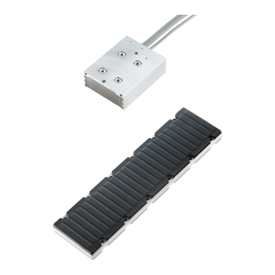
Technical description Technical description Design of the motors The linear servomotors from the AL2xxx series are brushless three-phase motors for high-quality servo applications. In conjunction with our digital servo drives they are particularly suitable for positioning tasks in industrial robots, machine tools, transfer lines, handling equipment, textile machines, packaging machines, etc. -
Page 18: Standard Features
Standard features Machine concept The AL2xxx linear servomotor series from Beckhoff is not a self-contained system. It includes various components such as a coil unit and magnetic plates and must be integrated into a complete machine concept or a complete working unit. -
Page 19: Magnetic Encoder System (Mes) (Optional)
Documentation for the Magnetic Encoder System (MES)! Further information on the Magnetic Encoder System (MES) can be found on the Beckhoff home- page under: MES Feedback Documentation or in the Beckhoff Online Information System. Additional equipment You require further components for the proper installation of your linear servomotor. -
Page 20: Servo Drive And Feedback System
Servo drive and feedback system The following components are required for the construction of a complete linear axis and its operation: • Servo drive, e.g.: AX5xxx from Beckhoff Automation GmbH. • Graduated rule and linear displacement transducer or the MES feedback system without graduated rule •... -
Page 21: Mechanical Installation
Mechanical installation Mechanical installation Important notes Installation of the machine bed must be complete before installing the linear motor components. The rails must be mounted on the machine bed and aligned. The carriage must be equipped with bearings, dampers and the required lines so that the proper movement of the carriage over the track is ensured. WARNING Damage due to uncontrolled magnetic attractive forces The sequence specified in this introduction for the installation must be followed. -
Page 22: Order Of Assembly Of The Work Unit
Mechanical installation Order of assembly of the work unit Fastening the coil unit Observe the following notes before beginning assembly. Deviations from flatness of the surface on which the coil unit will rest must be less than 0.1 mm. The coil unit must be assembled parallel to the magnetic plate. -
Page 23: Assembling The Magnetic Plates
Mechanical installation Assembling the magnetic plates Fastening the magnetic plates The textured side of the plate is the magnetic side. The magnetic plates exert a strong attractive force on all ferromagnetic metals such as iron. These forces cannot be controlled with the hands. They can cause serious injuries. -
Page 24: Attachment Of The Magnetic Plates
Mechanical installation 7.3.2 Attachment of the magnetic plates Fastening the magnetic plate to the machine bed Removing the protective plates Proceed as follows: Proceed as follows: • Align all the magnetic plates in the same direction. • Remove all protective plates. Example: •... -
Page 25: Coupling Of Linear Servomotors
Mechanical installation Coupling of linear servomotors Linear servomotors can be connected with one another in order to act together on a magnetic track. The forces of the motors are added together. The motors are connected in parallel to the controller, which leads to a higher total current. -
Page 26: Calculation Of The Offset
Mechanical installation 7.4.3 Calculation of the offset The wiring must be done according to the layout of the coil units. The offset must be determined in order to do this. The offset specifies the number of coils by which the rotary field is shifted in the second motor. The wiring of the motors can be determined with the help of the offset and the table in the section entitled Layout of the wiring [} 26]. -
Page 27: Positions Of The Phase Lines
Mechanical installation 7.4.5 Positions of the phase lines 7.4.5.1 Phase lines AL20xx 7.4.5.2 Phase lines AL24xx 7.4.5.3 Phase lines AL28xx-0 air-cooled Linear servomotor AL2xxx Version: 6.2... - Page 28 Mechanical installation 7.4.5.4 Phase lines AL28xx-1 water-cooled Version: 6.2 Linear servomotor AL2xxx...
-
Page 29: Minimum Distance Between The Motors
Mechanical installation 7.4.6 Minimum distance between the motors a) Motor cables pointing away from each other b) Motor cables pointing in the same direction c) Motor cables pointing towards each other = minimum distance between the motors = n * 16 – a – b n´ = auxiliary variable n = multiple of the phase spacing a = distance between phase line and housing wall of motor 1 (see previous page) B = distance between phase line and housing wall of motor 2 (see previous page) -
Page 30: Dismantling Sequence
Mechanical installation Dismantling sequence WARNING Damage due to uncontrolled magnetic attractive forces The dismantling sequence given in these instructions must be followed. A different sequence can give rise to dangerous situations, and can lead to damage resulting from uncontrolled magnetic attraction. Dismantling sequence: 1. -
Page 31: Electrical Installation
Connection with pre-assembled cables and connector box AL225x [} 34] • Use only cables approved by Beckhoff for the operation of the AL2xxx. • Route the power and encoder cables as separately as possible from one another (separation > 20 cm). -
Page 32: Connection Of Motors
Electrical installation Connection of motors 8.2.1 Single conductors If the motors are ordered with single conductors, any connector can be assembled. The assignment of the signals to the conductors is given in the tables below. Power Line Signal Green/Yellow Weave Shield Temperature contact Line... -
Page 33: M23 Connector For Power Supply And D-Sub Connector For Temperatur Contact
Electrical installation 8.2.2 M23 connector for power supply and D-Sub connector for temperatur contact Motors with connection plugs Power supply Temperature contact ZS4000-2040 ZS4000-2030 Power connector Contact Signal Connector M23 (8-poles) Case Shield Temperature contact Contact Signal D-Sub Connector (9-poles) Case Shield Linear servomotor AL2xxx... -
Page 34: Connection With Pre-Assembled Cables And Connector Box Al225X
Beckhoff offers preassembled motor and feedback cables for safe, faster and flawless installation of the motors. Beckhoff cables have been tested with regard to the materials, shielding and connectors used. They ensure proper functioning and compliance with statutory regulations such as EMC, UL etc. The use of other cables may lead to unexpected interference and invalidate the warranty. -
Page 35: Ax5000 Connection Diagram With Mes And Sin/Cos Encoder Without Zero Pulse
Electrical installation 8.3.1 AX5000 connection diagram with MES and Sin/Cos encoder without zero pulse * If no ConnectorBox is used, the ZK4540-0020-xxxx thermal protection contact cable is additionally required. This is to be connected to X14 / 24. Linear servomotor AL2xxx Version: 6.2... -
Page 36: Ax5000 Connection Diagram For Al2Xxx And Absolute Value Encoder
Electrical installation 8.3.2 AX5000 connection diagram for AL2xxx and absolute value encoder * If no ConnectorBox is used, the ZK4540-0020-xxxx thermal protection contact cable is additionally required. This is to be connected to X14 / 24. Version: 6.2 Linear servomotor AL2xxx... -
Page 37: Ax5000 Connection Diagram For Al2Xxx And Sin/Cos Encoder With Zero Pulse
Electrical installation 8.3.3 AX5000 connection diagram for AL2xxx and Sin/Cos encoder with zero pulse * If no ConnectorBox is used, the ZK4540-0020-xxxx thermal protection contact cable is additionally required. This is to be connected to X14 / 24. Linear servomotor AL2xxx Version: 6.2... -
Page 38: Ax5000 Connection Diagram For Al2Xxx And Ttl Encoder With Zero Pulse
Electrical installation 8.3.4 AX5000 connection diagram for AL2xxx and TTL encoder with zero pulse * If no ConnectorBox is used, the ZK4540-0020-xxxx thermal protection contact cable is additionally required. This is to be connected to X14 / 24. Version: 6.2 Linear servomotor AL2xxx... -
Page 39: Temperature Sensor
Electrical installation Temperature sensor The coil unit is equipped with two temperature sensors, a PTC-1kΩ and a KTY83-122. The temperature sensors are used to monitor the temperature in the coil unit. The temperature cable contains four wires. 8.4.1 PTC specification The PTC-1k sensor exhibits a sharp rise in temperature when the temperature is close to a certain critical value, and therefore operates as a digital indicator. -
Page 40: Polarity Test
All linear servomotors from Beckhoff are wired and connected in exactly the same way, so that a single test is sufficient in order to determine the polarity of a motor/graduated rule combination. If more than one axis is being constructed in a similar way, the polarity will be identical. -
Page 41: Installation Of The Water Cooling
In the case of the AL28xx series the water cooling represents an option that must be ordered explicitly so that it can be used. NOTE Consequential damages due to leaking water cooling Beckhoff can accept no responsibility for any damage resulting from a leaky water cooling system Requirements AL20xx AL28xx-100x... -
Page 42: Installation Of The Water Cooling Connections
Installation of the water cooling Installation of the water cooling connections 9.3.1 AL2xxx Make sure that the minimum diameter for water flow is at least 2.5 mm, and that the internal diameter of the hose is at least 4 mm. 1. -
Page 43: Connecting The Hoses
Installation of the water cooling Connecting the hoses NOTE Manufacturing the hoses The hoses must match the chosen connectors. The connectors must be free from oil and grease when the hoses are attached. The minimum flow rate is 1 l/ min, requiring a pressure drop of less than 1 bar. -
Page 44: Commissioning
Commissioning Commissioning 10.1 Important notes CAUTION Serious risk of injury! • Only specialist personnel with extensive knowledge in the areas of electrical engineering / drive tech- nology are allowed to install and commission the equipment. • Check that all live connection points are protected against accidental contact. •... -
Page 45: Optimising The Control Settings
Commissioning 10.2.2 Commissioning • Check that the drive elements (carriage, magnetic plate, coil unit) are tightly fastened and correctly adjusted. • Are the mechanical end-stops, limit switches and buffers properly dimensioned, and are they configured correctly? • Is the thermal protection contact cable connected? •... -
Page 46: Troubleshooting
Commissioning 10.3 Troubleshooting The following table describes possible faults and the measures to remedy them. There can be a large number of different reasons for a fault, depending on the particular conditions in your system. The fault causes described below are mostly those which directly influence the motor. Peculiarities which show up in the control behavior can usually be traced back to an error in the parameterization of the servo drives. -
Page 47: Technical Data
Technical data Technical data All details are based on a coil part with a coil temperature of 100°C mounted on an aluminum cooling surface. The cooling surface has a temperature of 20 °C and a thermal resistance of 0.05 K / W. 11.1 Term definitions Winding type... -
Page 48: Al20Xx
Technical data 11.2 AL20xx Technical data AL2003 AL2006 AL2009 AL2012 Winding type N / S N / S N / S Velocity (max.) 7 m/s 3.5 m/s (N) 2.5 m/s (N) 3.5 m/s (N) 7 m/s (S) 7 m/s (S) - Page 49 Technical data Technical data AL2015 AL2018 AL2024 Winding type N / S N / S N / S Velocity (max.) 3.5 m/s (N) 3.5 m/s (N) 3.5 m/s (N) 7 m/s (S) 7 m/s (S) 7 m/s (S) Motor configuration 3-phase synchronous linear motors (400 –...
-
Page 50: Dimensional Drawing, Al20Xx And Al21Xx
Technical data 11.2.1 Dimensional drawing, AL20xx and AL21xx Version: 6.2 Linear servomotor AL2xxx... -
Page 51: Al24Xx
Technical data 11.3 AL24xx Technical data AL2403 AL2406 AL2412 AL2418 Winding type Velocity (max.) 12 m/s 12 m/s 12 m/s 4.5 m/s 10 m/s Motor configuration 3-phase synchronous linear motors (400 – 480 V AC) Peak force (F 120 N 240 N 480 N 720 N... -
Page 52: Dimensional Drawing, Al24Xx And Al25Xx
Technical data 11.3.1 Dimensional drawing, AL24xx and AL25xx Version: 6.2 Linear servomotor AL2xxx... -
Page 53: Al28Xx-0 Air-Cooled
Technical data 11.4 AL28xx-0 air-cooled Technical data AL2812-000x AL2815-000x AL2830-000x Winding type N / S N / S N / S Velocity (max.) 3 m/s (N) 2.5 m/s (N) 2.5 m/s (N) 6 m/s (S) 6 m/s (S) 6 m/s (S) Motor configuration 3-phase synchronous linear motors (400 –... -
Page 54: Dimensional Drawing, Al28Xx-0 Air-Cooled And Al29Xx
Technical data 11.4.1 Dimensional drawing, AL28xx-0 air-cooled and AL29xx Version: 6.2 Linear servomotor AL2xxx... -
Page 55: Al28Xx-1 Water-Cooled
Technical data 11.5 AL28xx-1 water-cooled Technical data AL2818-100x AL2830-100x AL2845-100x Winding type N / S N / S N / S Velocity (max.) 3 m/s (N) 2.5 m/s (N) 2.5 m/s (N) 6 m/s (S) 6 m/s (S) 6 m/s (S) Motor configuration 3-phase synchronous linear motors (400 –... -
Page 56: Dimensional Drawing, Al28Xx-1 Water-Cooled And Al29Xx
Technical data 11.5.1 Dimensional drawing, AL28xx-1 water-cooled and AL29xx Version: 6.2 Linear servomotor AL2xxx... -
Page 57: Calculation Of The Brake Resistor
Technical data 11.6 Calculation of the brake resistor During the braking procedure of the linear axis, energy is fed back into the servo drive. During the design the regenerative power must be calculated in order to select a brake resistor if necessary. To do this the peak and continuous power must be calculated. -
Page 58: Support And Service
Beckhoff's branch offices and representatives Please contact your Beckhoff branch office or representative for local support and service on Beckhoff products! The addresses of Beckhoff's branch offices and representatives round the world can be found on her internet pages: http://www.beckhoff.com You will also find further documentation for Beckhoff components there.
Need help?
Do you have a question about the AL2009 and is the answer not in the manual?
Questions and answers