Table of Contents
Advertisement
Quick Links
Installation - Parts
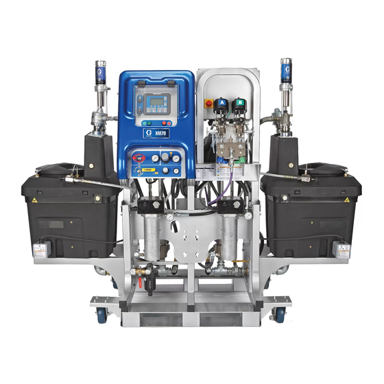
XM Plural-Component
OEM Sprayer
For spraying two-component epoxy and urethane protective coatings
in non-hazardous locations.
Important Safety Instructions
Read all warnings and instructions in this
manual. Save these instructions.
See page 6 for model information.
See page 31 for maximum working pressure.
313292E rev.b
ENG
Advertisement
Table of Contents

Related Manuals for Graco XM


Summary of Contents for Graco XM
- Page 1 Installation - Parts XM Plural-Component 313292E rev.b OEM Sprayer For spraying two-component epoxy and urethane protective coatings in non-hazardous locations. Important Safety Instructions Read all warnings and instructions in this manual. Save these instructions. See page 6 for model information.
-
Page 2: Table Of Contents
Pressure Relief Procedure ....14 Graco Information ......32... -
Page 3: Related Manuals
Related Manuals Related Manuals Manuals are available at www.graco.com. Component Manuals in U.S. English: Manual Description XM Plural-Component Sprayers 312359 Operation XM Plural-Component Sprayers 313289 Repair-Parts ® Xtreme Displacement Pumps 311762 Instructions-Parts ™ 311328 Air Motor Instructions-Parts Double Wall Hopper Kit... -
Page 4: Warnings
Warnings Warnings The following warnings are for the setup, use, grounding, maintenance, and repair of this equipment. The exclama- tion point symbol alerts you to a general warning and the hazard symbol refers to procedure-specific risk. Refer back to these warnings. Additional, product-specific warnings may be found throughout the body of this manual where applicable. - Page 5 Warnings WARNING PRESSURIZED EQUIPMENT HAZARD Fluid from the gun/dispense valve, leaks, or ruptured components can splash in the eyes or on skin and cause serious injury. • Follow Pressure Relief Procedure in this manual, when you stop spraying and before cleaning, checking, or servicing equipment.
-
Page 6: Models
Use the following matrix to define the construction of the sprayer, based on the six digits. For example, Part XMEA00 represents an XM Plural-Component OEM sprayer (XM); 5200 psi pump set with pump filters (E); wall power supply that is not approved for hazardous areas (A). -
Page 7: Overview
MSDS. interface, air controls, and fluid controls. Moisture Sensitivity of Isocyanates XM OEM sprayers are not approved for use in hazard- Isocyanates (ISO) are catalysts used in two component ous locations. urethane coatings. ISO will react with moisture (such as humidity) to form small, hard, abrasive crystals, which become suspended in the fluid. -
Page 8: Components A And B
Components A and B IMPORTANT! Material suppliers can vary in how they refer to plural component materials. XM OEM sprayers are not approved for use in hazard- ous locations. Be aware that in this manual: Component A refers to resin or major volume. -
Page 9: Component Identification
Component Identification Component Identification r_xmaa00_313292_2a . 1: Typical OEM Sprayer Components Key: Pump Assembly Air Controls (see Air Controls, page 11) Fluid Control Assembly (see Fluid Control Assembly, Air Inlet Manifold Assembly page 10) 68 Air Line Control Box 69 Air Line User Interface Display (see User Interface Display, page... -
Page 10: Fluid Control Assembly
Component Identification Fluid Control Assembly r_XM1A00_312359_313289_18A . 2: Fluid Control Assembly AA Dosing Valve A AF Sampling Valve B AB Dosing Valve B AG Restriction Valve AC Recirculation Valve A AH Mix Manifold Shutoff / Check Valve A AD Recirculation Valve B AJ Mix Manifold Shutoff / Check Valve B AE Sampling Valve A AK Solvent Shutoff Valve... -
Page 11: Air Controls
Component Identification Air Controls r_XM1A00_312359_313289_14A . 3: Air Controls CA Main Pump and Air On/Off Control CE Main Pump Air Regulator Gauge CB Solvent Pump Air On/Off Control CF Solvent Pump Air Gauge CC Inlet Air Pressure Gauge CG Solvent Pump Air Regulator CD Main Pump Air Regulator... -
Page 12: User Interface
Component Identification User Interface ti13365a . 4: User Interface Buttons LEDs There are four types of LEDs on the display. Call out Button Function Display Use to view GCA display. Ratio, Mode Call Screen Selection, Error Conditions, Totalizers, out LED Function System Information. - Page 13 Component Identification User Interface Display NOTE: For details regarding the user interface display see the XM Plural-Component Sprayer operation manual 312359. Main Display Screen Components The following figure calls out the navigational, status, and general informational components of each display screen.
-
Page 14: Pressure Relief Procedure
Pressure Relief Procedure Pressure Relief Procedure 8. Engage trigger lock. Follow Flush Mixed Material procedure prior to reliev- ing pressure. Follow Pressure Relief Procedure when you stop spraying or dispensing; and before cleaning, checking, ti1949a servicing, or transporting equipment. Relieve Pump Fluid Pressure and Flush Mix Hose Relieve A and B Fluid Pressure 9. - Page 15 Pressure Relief Procedure 12. Hold a metal part of the gun firmly to a grounded metal pail with a splash guard in place. Trigger gun to flush mixed material out of line with clean solvent. 13. Shut off solvent pump air control valve (CB). 14.
-
Page 16: Flush Mixed Material
Flush Mixed Material Flush Mixed Material 3. Open solvent shutoff valve (AK) at mix manifold. 4. Open solvent pump air valve (CB). Pull out and slowly turn solvent pump air regulator (CG) clock- wise to increase air pressure. Use lowest possible Flush Mix Manifold pressure. - Page 17 Flush Mixed Material 6. Close solvent pump air valve (CB) and solvent shut- off valve (AK) at mix manifold. Trigger spray gun to relieve pressure. 7. Engage trigger lock. ti1949a 8. Disassemble and clean spray tip with solvent by hand. Reinstall on gun.
-
Page 18: Installation And Setup
(Hose called out has 12(A) and 12 (B)). Connect Air Lines Refer to component identification in F . 1, page 9. Refer to the pneumatic schematic drawings in the XM 12(B) Plural-Component Sprayer repair-parts manual 313289 for guidance. •... -
Page 19: Operation
Operation Operation For operation instructions, see XM Plural-Component Sprayer Operation manual 312359. Repair For maintenance, troubleshooting, and repair instruc- tions, see XM Plural-Component Sprayer Repair-Parts manual 313289. Schematics See XM Plural-Component Sprayer Repair-Parts man- ual 313289 for all electrical schematics. -
Page 20: Parts
Parts Parts (FRONT VIEW) (REAR VIEW) (REAR VIEW) (FRONT VIEW) - Page 21 Parts XM_D00 Systems Only XM_A00 Systems Only...
-
Page 22: Xma_00 And Xmb_00 Parts
Parts XMA_00 and XMB_00 Parts Ref. Part Description Qty. 63 117623 NUT, cap; 3/8-16 unc NOTE: Reference numbers not listed are not 64 24A034 CARRIAGE included with XMA_00 and XMB_00 systems. 111801 SCREW, cap, hex hd 108636 MUFFLER 121688 CONNECTOR, 3/8 npt x 3/8 tube Ref. -
Page 23: Xme_00 And Xmf_00 Parts
Parts XME_00 and XMF_00 Parts Ref. Part Description Qty. 41 15X126 LABEL, codes NOTE: Reference numbers not listed are not 42 15W598 LABEL, warning included with XME_00 and XMF_00 systems. 43 156971 NIPPLE, short 44 115243 REGULATOR, air; 1/4 npt 45... -
Page 24: Xmg_00 And Xmh_00 Parts
Parts XMG_00 and XMH_00 Parts Ref. Part Description Qty. 41 15X126 LABEL, codes NOTE: Reference numbers not listed are not 42 15W598 LABEL, warning included with XMG_00 and XMH_00 systems. 43‡ 156971 NIPPLE, short 44‡ 115243 REGULATOR, air; 1/4 npt 45‡... -
Page 25: Accessories And Kits
7-Gallon Hopper and Bracket Kit, 256260 One 7-gallon hopper and mounting brackets. Mounts to Electric Heated Hose Power Supply Kit, the side or back of an XM sprayer. See manual 406999 256876 for more information. For monitoring and controlling fluid temperature in low-voltage heated hoses. - Page 26 5000 psi Two-Component Main Heated Alternator Conversion Kit, 256991 Hose Set Kit For converting an XM sprayer from wall power supply to intrinsically safe alternator power supply. See manual Electric heated hose set for adding additional sections. 313293 for more information.
- Page 27 Accessories and Kits...
-
Page 28: Dimensions
Dimensions Dimensions 0.205 in. Fluid Control Assembly (5.21 mm) Mounting Plate DOSING MOUNTING PLANE MANIFOLD MOUNTING PLANE 1.440 in. 1.440 in. (36.58 mm) (36.58 mm) 1.440 in. (36.58 mm) 3.970 in. (100.84 mm) 8 X FULL R .380 2.180 in. (55.37 mm) r_xma000_313292_11a 4.940 in. - Page 29 Dimensions Fluid Control Assembly Dosing Valve Assembly 1.440 in. (36.58 mm) 4 X 5/16-18 UNC 2B 1.440 in. (36.58 mm) Mix Manifold Assembly r_xma000_313292_10a 6.380 in. (162.05 mm) 1.440 in. 1.440 in. (36.58 mm) (36.58 mm) 1.440 in. (36.58 mm) 8 X 5/16-18 UNC 2B 4.940 in.
- Page 30 Dimensions 15.250 in. (387.35 mm) 6.940 in. (176.28 mm) Control Box Assembly 10.000 in. 15.000 in. (254.00 mm) (381.00 mm) 19.000 in. 4 X FULL R .500 (482.60 mm) r_xma000_313292_7a 3.130 in. (79.50 mm) Air Control Assembly 0.750 in. 8 X FULL R .440 (19.05 mm) 2.000 in.
-
Page 31: Technical Data
Technical Data Technical Data Mixed ratio range ....... 1:1-10:1 (in 0.1 increments) Ratio tolerance range . -
Page 32: Graco Standard Warranty
With the exception of any special, extended, or limited warranty published by Graco, Graco will, for a period of twelve months from the date of sale, repair or replace any part of the equipment determined by Graco to be defective.
Need help?
Do you have a question about the XM and is the answer not in the manual?
Questions and answers