Table of Contents
Advertisement
Quick Links
www.ti.com
User's Guide
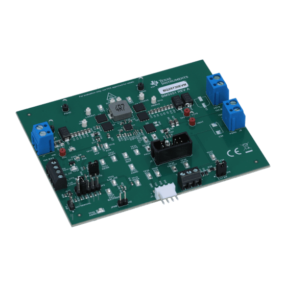
BQ2573X Evaluation Module
The BQ25730EVM and BQ25731EVM evaluation modules (EVM) are I
charger. The input voltage range is between 3.5 V and 26 V, with a programmable output of 1-5 cells and a
charge output current range of 128 mA to 15 A. This EVM does not include the EV2400 interface device. The
EV2400 must be ordered separately to evaluate the BQ2573X EVM.
1
Introduction.............................................................................................................................................................................2
1.1 EVM Features....................................................................................................................................................................
1.2 General Description...........................................................................................................................................................
2 Test Summary.........................................................................................................................................................................
2.1 Definitions..........................................................................................................................................................................
2.2 Equipment..........................................................................................................................................................................
Setup................................................................................................................................................................6
2.4
Procedure...........................................................................................................................................................................9
Materials.................................................................................................................................................................10
3.2 Board Assembly Layout...................................................................................................................................................
3.3 Schematic........................................................................................................................................................................
History.......................................................................................................................................................................21
Figure 2-2. Original Test Setup for BMS051 (BQ2573X EVM)....................................................................................................
Figure 2-3. BQ2573X Evaluation Software Main Window...........................................................................................................
Figure 2-4.
EN_OTG....................................................................................................................................................................9
Figure 3-1. Top Assembly..........................................................................................................................................................
Figure 3-2. Bottom Assembly....................................................................................................................................................
Figure 3-3. PCB Layer 1............................................................................................................................................................
Figure 3-4. PCB Layer 2............................................................................................................................................................
Figure 3-5. PCB Layer 3............................................................................................................................................................
Figure 3-6. PCB Layer 4............................................................................................................................................................
Table 1-1. I/O Description............................................................................................................................................................
Table 3-1. BQ2573X EVM Bill of Materials................................................................................................................................
Trademarks
USB Type-C
™
is a trademark of USB Implementer's Forum, Inc..
All trademarks are the property of their respective owners.
SLUUCB9A - JUNE 2020 - REVISED JANUARY 2021
Submit Document Feedback
Table of Contents
Schematics...............................................................................................................10
List of Figures
Schematic.......................................................................................................................................19
Schematic.......................................................................................................................................20
List of Tables
Setting.........................................................................................................................3
Conditions.........................................................................................................................4
Copyright © 2021 Texas Instruments Incorporated
ABSTRACT
2
C-controlled NVDC-1 buck boost
Table of Contents
2
2
5
5
5
13
19
7
8
13
14
15
16
17
18
2
10
BQ2573X Evaluation Module
1
Advertisement
Table of Contents

Subscribe to Our Youtube Channel
Related Manuals for Texas Instruments BQ2573 Series


Summary of Contents for Texas Instruments BQ2573 Series
-
Page 1: Table Of Contents
USB Type-C ™ is a trademark of USB Implementer's Forum, Inc.. All trademarks are the property of their respective owners. SLUUCB9A – JUNE 2020 – REVISED JANUARY 2021 BQ2573X Evaluation Module Submit Document Feedback Copyright © 2021 Texas Instruments Incorporated... -
Page 2: Table 1-1. I/O Description
I/O descriptions. Table 1-1. I/O Description Jack Description J1–VIN Input: positive terminal J1–PGND Input: negative terminal (ground terminal) J2-CHRG_OK CHRG_OK output BQ2573X Evaluation Module SLUUCB9A – JUNE 2020 – REVISED JANUARY 2021 Submit Document Feedback Copyright © 2021 Texas Instruments Incorporated... -
Page 3: Introduction
Jumper on: Onboard LDO to drive the EVM 3V3 Installed Jumper off: disconnect onboard LDO to drive the EVM 3V3 SLUUCB9A – JUNE 2020 – REVISED JANUARY 2021 BQ2573X Evaluation Module Submit Document Feedback Copyright © 2021 Texas Instruments Incorporated... -
Page 4: Table 1-3. Recommended Operating Conditions
Maximum input current from ac adapter Supply current, I input Output current, I Output current Operating junction temperature °C range, T BQ2573X Evaluation Module SLUUCB9A – JUNE 2020 – REVISED JANUARY 2021 Submit Document Feedback Copyright © 2021 Texas Instruments Incorporated... -
Page 5: Test Summary
A computer with at least one USB port and a USB cable. 6. EV2400 Communication Kit 7. Software Download and properly install BQstudio from http://www.ti.com/tool/BQstudio. SLUUCB9A – JUNE 2020 – REVISED JANUARY 2021 BQ2573X Evaluation Module Submit Document Feedback Copyright © 2021 Texas Instruments Incorporated... -
Page 6: Equipment Setup
The picture shows the SMBus version EVM connection. For I C version, move the connector to the I C port. Figure 2-1. EV2400 Connections BQ2573X Evaluation Module SLUUCB9A – JUNE 2020 – REVISED JANUARY 2021 Submit Document Feedback Copyright © 2021 Texas Instruments Incorporated... -
Page 7: Figure 2-2. Original Test Setup For Bms051 (Bq2573X Evm)
After selecting the target device, change “update mode” from “immediate” to “manual”, click “Read Register” and the following interface is presented. SLUUCB9A – JUNE 2020 – REVISED JANUARY 2021 BQ2573X Evaluation Module Submit Document Feedback Copyright © 2021 Texas Instruments Incorporated... -
Page 8: Figure 2-3. Bq2573X Evaluation Software Main Window
Test Summary www.ti.com Figure 2-3. BQ2573X Evaluation Software Main Window BQ2573X Evaluation Module SLUUCB9A – JUNE 2020 – REVISED JANUARY 2021 Submit Document Feedback Copyright © 2021 Texas Instruments Incorporated... -
Page 9: Procedure
4. Remove JP2 (Enable OTG/VAP function). 5. Select EN_OTG in Charge Option 3. Measure → V(J1(V )) = 5 V ±1 V Figure 2-4. EN_OTG SLUUCB9A – JUNE 2020 – REVISED JANUARY 2021 BQ2573X Evaluation Module Submit Document Feedback Copyright © 2021 Texas Instruments Incorporated... -
Page 10: Bill Of Materials, Board Layout, And Schematics
Header, 100mil, 2x1, Gold, TH Header, 2x1, 100mil 5-146261-1 TE Connectivity Header, 100mil, 5x2, Gold, TH 5x2 Header TSW-105-07-G-D Samtec BQ2573X Evaluation Module SLUUCB9A – JUNE 2020 – REVISED JANUARY 2021 Submit Document Feedback Copyright © 2021 Texas Instruments Incorporated... - Page 11 RES, 33 k, 5%, 0.1 W, AEC-Q200 Grade 0, 0603 CRCW060333K0JNEA Vishay-Dale SH-JP2, SH-JP3, Shunt, 100mil, Gold plated, Black Shunt SNT-100-BK-G Samtec SH-JP8 SLUUCB9A – JUNE 2020 – REVISED JANUARY 2021 BQ2573X Evaluation Module Submit Document Feedback Copyright © 2021 Texas Instruments Incorporated...
- Page 12 Samtec 1. For BQ25730EVM, Install Q5 and do not install R46; For BQ25731EVM, Install R46 and do not install Q5. BQ2573X Evaluation Module SLUUCB9A – JUNE 2020 – REVISED JANUARY 2021 Submit Document Feedback Copyright © 2021 Texas Instruments Incorporated...
-
Page 13: Board Assembly Layout
Bill of Materials, Board Layout, and Schematics 3.2 Board Assembly Layout Figure 3-1 Figure 3-6 illustrate the board assembly layout images. Figure 3-1. Top Assembly SLUUCB9A – JUNE 2020 – REVISED JANUARY 2021 BQ2573X Evaluation Module Submit Document Feedback Copyright © 2021 Texas Instruments Incorporated... -
Page 14: Figure 3-2. Bottom Assembly
Bill of Materials, Board Layout, and Schematics www.ti.com Figure 3-2. Bottom Assembly BQ2573X Evaluation Module SLUUCB9A – JUNE 2020 – REVISED JANUARY 2021 Submit Document Feedback Copyright © 2021 Texas Instruments Incorporated... -
Page 15: Figure 3-3. Pcb Layer 1
Bill of Materials, Board Layout, and Schematics Figure 3-3. PCB Layer 1 SLUUCB9A – JUNE 2020 – REVISED JANUARY 2021 BQ2573X Evaluation Module Submit Document Feedback Copyright © 2021 Texas Instruments Incorporated... -
Page 16: Figure 3-4. Pcb Layer 2
Bill of Materials, Board Layout, and Schematics www.ti.com Figure 3-4. PCB Layer 2 BQ2573X Evaluation Module SLUUCB9A – JUNE 2020 – REVISED JANUARY 2021 Submit Document Feedback Copyright © 2021 Texas Instruments Incorporated... -
Page 17: Figure 3-5. Pcb Layer 3
Bill of Materials, Board Layout, and Schematics Figure 3-5. PCB Layer 3 SLUUCB9A – JUNE 2020 – REVISED JANUARY 2021 BQ2573X Evaluation Module Submit Document Feedback Copyright © 2021 Texas Instruments Incorporated... -
Page 18: Figure 3-6. Pcb Layer 4
Bill of Materials, Board Layout, and Schematics www.ti.com Figure 3-6. PCB Layer 4 BQ2573X Evaluation Module SLUUCB9A – JUNE 2020 – REVISED JANUARY 2021 Submit Document Feedback Copyright © 2021 Texas Instruments Incorporated... -
Page 19: Schematic
Receptacle_4x1 TP36 10.0k 10.0 10.0k PM-REG-LM3480-SOT3 TP37 2.0M TP38 0.1uF 0.1uF Receptacle_3x1 300k N2510-6002-RB PGND Figure 3-7. BQ25730 EVM Schematic SLUUCB9A – JUNE 2020 – REVISED JANUARY 2021 BQ2573X Evaluation Module Submit Document Feedback Copyright © 2021 Texas Instruments Incorporated... -
Page 20: Figure 3-8. Bq25731 Evm Schematic
TP37 2.0M TP38 0.1uF 0.1uF Receptacle_3x1 300k N2510-6002-RB PGND Figure 3-8. BQ25731 EVM Schematic 1. DNP means "Do Not Populate". BQ2573X Evaluation Module SLUUCB9A – JUNE 2020 – REVISED JANUARY 2021 Submit Document Feedback Copyright © 2021 Texas Instruments Incorporated... -
Page 21: Revision History
Changes from Revision * (June 2020) to Revision A (January 2021) Page • Updated the numbering format for tables, figures and cross-references throughout the document....1 • Updated all figures..............................1 SLUUCB9A – JUNE 2020 – REVISED JANUARY 2021 BQ2573X Evaluation Module Submit Document Feedback Copyright © 2021 Texas Instruments Incorporated... - Page 22 STANDARD TERMS FOR EVALUATION MODULES Delivery: TI delivers TI evaluation boards, kits, or modules, including any accompanying demonstration software, components, and/or documentation which may be provided together or separately (collectively, an “EVM” or “EVMs”) to the User (“User”) in accordance with the terms set forth herein.
- Page 23 www.ti.com Regulatory Notices: 3.1 United States 3.1.1 Notice applicable to EVMs not FCC-Approved: FCC NOTICE: This kit is designed to allow product developers to evaluate electronic components, circuitry, or software associated with the kit to determine whether to incorporate such items in a finished product and software developers to write software applications for use with the end product.
- Page 24 www.ti.com Concernant les EVMs avec antennes détachables Conformément à la réglementation d'Industrie Canada, le présent émetteur radio peut fonctionner avec une antenne d'un type et d'un gain maximal (ou inférieur) approuvé pour l'émetteur par Industrie Canada. Dans le but de réduire les risques de brouillage radioélectrique à...
- Page 25 www.ti.com EVM Use Restrictions and Warnings: 4.1 EVMS ARE NOT FOR USE IN FUNCTIONAL SAFETY AND/OR SAFETY CRITICAL EVALUATIONS, INCLUDING BUT NOT LIMITED TO EVALUATIONS OF LIFE SUPPORT APPLICATIONS. 4.2 User must read and apply the user guide and other available documentation provided by TI regarding the EVM prior to handling or using the EVM, including without limitation any warning or restriction notices.
- Page 26 Notwithstanding the foregoing, any judgment may be enforced in any United States or foreign court, and TI may seek injunctive relief in any United States or foreign court. Mailing Address: Texas Instruments, Post Office Box 655303, Dallas, Texas 75265 Copyright © 2019, Texas Instruments Incorporated...
- Page 27 TI products. TI’s provision of these resources does not expand or otherwise alter TI’s applicable warranties or warranty disclaimers for TI products.IMPORTANT NOTICE Mailing Address: Texas Instruments, Post Office Box 655303, Dallas, Texas 75265 Copyright © 2021, Texas Instruments Incorporated...
Need help?
Do you have a question about the BQ2573 Series and is the answer not in the manual?
Questions and answers