Advertisement
Quick Links
www.ti.com
EVM User's Guide: BQ25756EVM
BQ25756 Evaluation Module
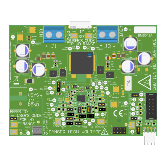
Description
The BQ25756EVM evaluation module (EVM) is a
complete evaluation system for the BQ25756 IC, a
buck-boost battery charge controller with a wide input
range of 4.2 V - 70 V, a wide output voltage range of
up to 70 V, and bi-directional capabilities.
The BQ25756EVM has a max input and output of 55
V and a max charge current of 10 A.
Get Started
1. Order the EVM on
ti.com
2. Order the
EV2400
to communicate with the EVM
3. Download the BQ25756 BQZ file
4. Download the BQ25756 EVM design files on
ti.com
SLUUCT7B – MAY 2023 – REVISED AUGUST 2023
Submit Document Feedback
Features
•
Wide input voltage operating range: 4.2 V–55 V
•
Wide output operating range: up to 55 V with
CC/CV support for:
– 2– to 13–Cell Li-Ion
– 2– to 14–Cell LiFePO4
•
Synchronous buck-boost DC/DC charge controller
with NFET drivers
– Adjustable switching frequency from 200 kHz to
– Optional synchronization to external clock
– Optional gate driver supply input for optimized
•
Resistor-programmable standalone with added I2C
Mode
•
Built in MPPT to maximize power from solar panel
arrays
•
Power up from battery (reverse mode) output 4 V
to 55 V
•
High safety integration
– Adjustable input overvoltage and undervoltage
– Output Overvoltage and overcurrent protection
Copyright © 2023 Texas Instruments Incorporated
600 kHz
efficiency
protection
BQ25756 Evaluation Module
Description
1
Advertisement

Related Manuals for Texas Instruments BQ25756


Summary of Contents for Texas Instruments BQ25756
- Page 1 The BQ25756EVM evaluation module (EVM) is a • Wide input voltage operating range: 4.2 V–55 V complete evaluation system for the BQ25756 IC, a • Wide output operating range: up to 55 V with buck-boost battery charge controller with a wide input CC/CV support for: range of 4.2 V - 70 V, a wide output voltage range of...
-
Page 2: Kit Contents
1.3 Device Information The BQ25756EVM evaluation module (EVM) is an evaluation system for the BQ25756 IC. The BQ25756 IC is a buck-boost battery charge controller with a wide input range of 4.2 V - 70 V, a wide output voltage range of up to 70 V, and bi-directional capabilities. - Page 3 Evaluation Module Overview 1.4 General Texas Instruments High Voltage Evaluation (TI HV EMV) User Safety Guidelines WARNING Always follow TI's set-up and application instructions, including use of all interface components within their recommended electrical rated voltage and power limits. Always use electrical safety precautions to help verify your personal safety and those working around you.
- Page 4 The circuit module has signal traces, components, and component leads on the bottom of the board. This can result in exposed voltages, hot surfaces or sharp edges. Do not reach under the board during operation. BQ25756 Evaluation Module SLUUCT7B – MAY 2023 – REVISED AUGUST 2023 Submit Document Feedback Copyright © 2023 Texas Instruments Incorporated...
- Page 5 CAUTION The board has no fuse installed and relies on the external voltage source current limit to verify circuit protection. SLUUCT7B – MAY 2023 – REVISED AUGUST 2023 BQ25756 Evaluation Module Submit Document Feedback Copyright © 2023 Texas Instruments Incorporated...
- Page 6 Connection for external gate drive J7-Power Connector Connection for VAC and BAT J8-Communication Port Connection for EXT_DRV, /INT, I2C, /PG, and 3.3 V BQ25756 Evaluation Module SLUUCT7B – MAY 2023 – REVISED AUGUST 2023 Submit Document Feedback Copyright © 2023 Texas Instruments Incorporated...
-
Page 7: Recommended Operating Conditions
Default EVM input current limit is set to 8 A through the IIN pin. The current limiting feature can be disabled by setting EN_IIN_PIN bit to '0', changing IIN pin resistor, or shorting IIN pin to PGND through JP11. SLUUCT7B – MAY 2023 – REVISED AUGUST 2023 BQ25756 Evaluation Module Submit Document Feedback Copyright © 2023 Texas Instruments Incorporated... -
Page 8: Power Supplies
3. Connect a voltage meter across J1 (VIN) and J1 (PGND). 4. Connect load #1 in series with a current meter to J3 (VBAT and PGND). BQ25756 Evaluation Module SLUUCT7B – MAY 2023 – REVISED AUGUST 2023 Submit Document Feedback Copyright © 2023 Texas Instruments Incorporated... - Page 9 13. Set power supply #1 for 40 V, measure V(J1(VAC)) = 40 V ± 0.5 V I(J1(IAC)) = 2.4 A ± 0.5 A SLUUCT7B – MAY 2023 – REVISED AUGUST 2023 BQ25756 Evaluation Module Submit Document Feedback Copyright © 2023 Texas Instruments Incorporated...
- Page 10 A computer with at least one USB port and a USB cable. 5. EV2400 Communication Kit: 6. Software: Download and properly install bqStudio from https://www.ti.com/tool/BQSTUDIO. BQ25756 Evaluation Module SLUUCT7B – MAY 2023 – REVISED AUGUST 2023 Submit Document Feedback Copyright © 2023 Texas Instruments Incorporated...
- Page 11 Select Charger_1_00_BQ25756.bqz on the Select a Target Page. c. After selecting the target device, click Field View and then click the Read Register button. SLUUCT7B – MAY 2023 – REVISED AUGUST 2023 BQ25756 Evaluation Module Submit Document Feedback Copyright © 2023 Texas Instruments Incorporated...
- Page 12 The following sections includes the hardware design files for BQ25756EVM. This section includes the schematics, board layouts, and Bill of Materials (BOM). BQ25756 Evaluation Module SLUUCT7B – MAY 2023 – REVISED AUGUST 2023 Submit Document Feedback Copyright © 2023 Texas Instruments Incorporated...
- Page 13 STAT1 100nF STAT2 STAT2 PGND 100V BQ25756 PGND PGND MODE 0.1% 13.7k PGND 3.00k PGND Figure 3-1. BQ25756 EVM Schematic SLUUCT7B – MAY 2023 – REVISED AUGUST 2023 BQ25756 Evaluation Module Submit Document Feedback Copyright © 2023 Texas Instruments Incorporated...
- Page 14 C517 C518 C519 C506 C507 15uF 15uF 15uF 15uF 15uF 15uF 100nF D 100V 100k 100k 100V 1µF 100V PGND BQ25756 Evaluation Module SLUUCT7B – MAY 2023 – REVISED AUGUST 2023 Submit Document Feedback Copyright © 2023 Texas Instruments Incorporated...
- Page 15 TP37 TP38 TP39 TP47 TP40 HIDRV1 BTST1 HIDRV2 BTST2 STAT1 /INT STAT2 3V3_PULLUP PGND PGND PGND PGND PGND PGND PGND SLUUCT7B – MAY 2023 – REVISED AUGUST 2023 BQ25756 Evaluation Module Submit Document Feedback Copyright © 2023 Texas Instruments Incorporated...
- Page 16 For BQ25758 variant, Install JP4, JP5, JP6, JP9, JP10, pin 1-2 of JP12, JP13, JP14, JP15, and JP16 Assembly Note For BQ25756 variant, Install JP1, JP4, JP5, JP6, JP9, JP10, pin 1-2 of JP12, JP13, JP14, JP15, and JP16 1. DNP means "Do Not Populate".
-
Page 17: Pcb Layout
Hardware Design Files 3.2 PCB Layout Figure 3-2. Top Layer and Overlay Figure 3-3. Layer 2 -GND SLUUCT7B – MAY 2023 – REVISED AUGUST 2023 BQ25756 Evaluation Module Submit Document Feedback Copyright © 2023 Texas Instruments Incorporated... - Page 18 Hardware Design Files www.ti.com Figure 3-4. Single Layer 1 Figure 3-5. Signal Layer 2 BQ25756 Evaluation Module SLUUCT7B – MAY 2023 – REVISED AUGUST 2023 Submit Document Feedback Copyright © 2023 Texas Instruments Incorporated...
- Page 19 Hardware Design Files Figure 3-6. Layer 5 - GND Figure 3-7. Bottom Layer SLUUCT7B – MAY 2023 – REVISED AUGUST 2023 BQ25756 Evaluation Module Submit Document Feedback Copyright © 2023 Texas Instruments Incorporated...
- Page 20 Diode Standard 100 V 1 A Surface Mount DO-214AC DO-214AC (SMA) H1, H2, H3, H4 SJ-5303 (CLEAR) Bumpon, Hemisphere, 0.44 X 0.20, Clear Transparent Bumpon BQ25756 Evaluation Module SLUUCT7B – MAY 2023 – REVISED AUGUST 2023 Submit Document Feedback Copyright © 2023 Texas Instruments Incorporated...
- Page 21 (11050 Metric), 2043 Current Sense, Moisture Resistant Metal Foil 133k ERJ-6ENF1333V Panasonic RES, 133 k, 1%, 0.125 W, AEC-Q200 Grade 0, 0805 SLUUCT7B – MAY 2023 – REVISED AUGUST 2023 BQ25756 Evaluation Module Submit Document Feedback Copyright © 2023 Texas Instruments Incorporated...
- Page 22 Samtec Shunt, 100mil, Gold plated, Black Shunt JP2, SH-JP3, SH-JP4, SH- JP5, SH-JP6, SH-JP7, SH- JP8, SH-JP9, SH-JP10, SH- JP11 BQ25756 Evaluation Module SLUUCT7B – MAY 2023 – REVISED AUGUST 2023 Submit Document Feedback Copyright © 2023 Texas Instruments Incorporated...
- Page 23 BQ25756RRVT Texas Instruments BQ25756RRVT VQFN36 LT3010EMS8E-PBF Analog Devices Linear Voltage Regulator IC Positive MSOP8 Adjustable 1 Output 50 mA 8-MSOP-EP SLUUCT7B – MAY 2023 – REVISED AUGUST 2023 BQ25756 Evaluation Module Submit Document Feedback Copyright © 2023 Texas Instruments Incorporated...
-
Page 24: Revision History
Added limits of the BQ25756 EVM........................• Changed IC voltage range to the most current....................2 • Changed first sentence to emphasize and expand on the capabilities of BQ25756 ......... • Changed BQ25758 to BQ25756.........................7 • Changed output power to 400 W........................7... - Page 25 STANDARD TERMS FOR EVALUATION MODULES Delivery: TI delivers TI evaluation boards, kits, or modules, including any accompanying demonstration software, components, and/or documentation which may be provided together or separately (collectively, an “EVM” or “EVMs”) to the User (“User”) in accordance with the terms set forth herein.
- Page 26 www.ti.com Regulatory Notices: 3.1 United States 3.1.1 Notice applicable to EVMs not FCC-Approved: FCC NOTICE: This kit is designed to allow product developers to evaluate electronic components, circuitry, or software associated with the kit to determine whether to incorporate such items in a finished product and software developers to write software applications for use with the end product.
- Page 27 www.ti.com Concernant les EVMs avec antennes détachables Conformément à la réglementation d'Industrie Canada, le présent émetteur radio peut fonctionner avec une antenne d'un type et d'un gain maximal (ou inférieur) approuvé pour l'émetteur par Industrie Canada. Dans le but de réduire les risques de brouillage radioélectrique à...
- Page 28 www.ti.com EVM Use Restrictions and Warnings: 4.1 EVMS ARE NOT FOR USE IN FUNCTIONAL SAFETY AND/OR SAFETY CRITICAL EVALUATIONS, INCLUDING BUT NOT LIMITED TO EVALUATIONS OF LIFE SUPPORT APPLICATIONS. 4.2 User must read and apply the user guide and other available documentation provided by TI regarding the EVM prior to handling or using the EVM, including without limitation any warning or restriction notices.
- Page 29 Notwithstanding the foregoing, any judgment may be enforced in any United States or foreign court, and TI may seek injunctive relief in any United States or foreign court. Mailing Address: Texas Instruments, Post Office Box 655303, Dallas, Texas 75265 Copyright © 2023, Texas Instruments Incorporated...
- Page 30 TI products. TI’s provision of these resources does not expand or otherwise alter TI’s applicable warranties or warranty disclaimers for TI products. TI objects to and rejects any additional or different terms you may have proposed. IMPORTANT NOTICE Mailing Address: Texas Instruments, Post Office Box 655303, Dallas, Texas 75265 Copyright © 2023, Texas Instruments Incorporated...
-
Page 31: Texas Instruments
Mouser Electronics Authorized Distributor Click to View Pricing, Inventory, Delivery & Lifecycle Information: Texas Instruments BQ25756EVM...
Need help?
Do you have a question about the BQ25756 and is the answer not in the manual?
Questions and answers