Advertisement
Quick Links
www.ti.com
EVM User's Guide: BQ25756EEVM
BQ25756E Evaluation Module
Description
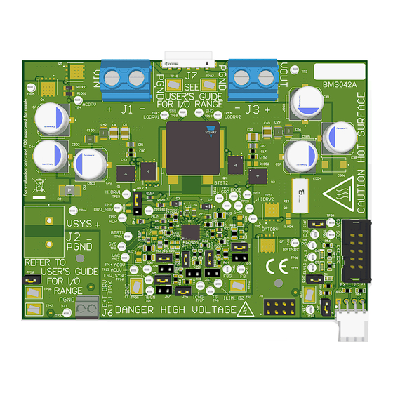
The BQ25756EEVM evaluation module (EVM) is a
complete evaluation system for the BQ25756E IC, a
buck-boost battery charge controller with a wide input
range of 4.2 V - 36 V, a wide output voltage range of
up to 36 V, and bi-directional capabilities.
The BQ25756EEVM has a max input and output of 36
V and a max charge current of 10 A.
Get Started
1. Order the EVM on
ti.com
2. Order the
EV2400
to communicate with the EVM
3. Download the BQ25756E BQZ file
4. Download the BQ25756E EVM design files on
ti.com
SLUUCY5 – NOVEMBER 2023
Submit Document Feedback
Features
•
Wide input voltage operating range: 4.2 V–36 V
•
Wide output operating range: up to 36 V with
CC/CV support for:
– 2– to 7–Cell Li-Ion
– 2– to 9–Cell LiFePO4
•
Synchronous buck-boost DC/DC charge controller
with NFET drivers
– Adjustable switching frequency from 200 kHz to
– Optional synchronization to external clock
– Optional gate driver supply input for optimized
•
Resistor-programmable standalone with added I2C
Mode
•
Built in MPPT to maximize power from solar panel
arrays
•
Power up from battery (reverse mode) output 4 V
to 36 V
•
High safety integration
– Adjustable input overvoltage and undervoltage
– Output Overvoltage and overcurrent protection
Copyright © 2023 Texas Instruments Incorporated
600 kHz
efficiency
protection
BQ25756E Evaluation Module
Description
1
Advertisement

Related Manuals for Texas Instruments BQ25756EEVM


Summary of Contents for Texas Instruments BQ25756EEVM
- Page 1 – 2– to 9–Cell LiFePO4 • Synchronous buck-boost DC/DC charge controller The BQ25756EEVM has a max input and output of 36 with NFET drivers V and a max charge current of 10 A. – Adjustable switching frequency from 200 kHz to...
-
Page 2: Kit Contents
1 Evaluation Module Overview 1.1 Introduction The BQ25756EEVM can be evaluated for up to 180 W range of USB Extended Power Range (EPR) and up to 7 cell Li-Ion battery charging implementing CC/CV profile. Typical applications include Kick eScooters, cordless power tools, garden tools, robotic lawn mowers, portable power stations, cordless vacuum cleaners, vacuum robots, solar chargers, and USB-PD EPR applications. - Page 3 Evaluation Module Overview 1.4 General Texas Instruments High Voltage Evaluation (TI HV EMV) User Safety Guidelines WARNING Always follow TI's set-up and application instructions, including use of all interface components within their recommended electrical rated voltage and power limits. Always use electrical safety precautions to help verify your personal safety and those working around you.
-
Page 4: General Safety Information
The following warnings and cautions are noted for the safety of anyone using or working close to the BQ25756E EVM. Observe all safety precautions. The BQ25756EEVM circuit module can become hot during operation due to dissipation of heat. Avoid contact with the board. Follow all applicable safety procedures applicable to your laboratory. - Page 5 CAUTION The board does not have a fuse installed and relies on the external voltage source current limit to verify circuit protection. SLUUCY5 – NOVEMBER 2023 BQ25756E Evaluation Module Submit Document Feedback Copyright © 2023 Texas Instruments Incorporated...
- Page 6 Hardware www.ti.com 2 Hardware 2.1 Board Parameters Table 2-1. Default board setup for BQ25756EEVM Description Value Unit ACUV Input undervoltage ACOV Input overvoltage Input current of the EVM IOUT Output current of the EVM FSW_SYNC Switching frequency of the power stage Table 2-2.
-
Page 7: Recommended Operating Conditions
JP15 general purpose indicator. JP16 Shunt JP16 to generate on board 3.3-V pullup rail. Installed 2.3 Recommended Operating Conditions Table 2-5. Recommended Operating Conditions for BQ25756EEVM Description UNIT VIN (J1) Input voltage to the EVM VOUT (J3) Output voltage of the EVM... -
Page 8: Power Supplies
A computer with at least one USB port and a USB cable. 5. EV2400 Communication Kit: 6. Software: Download and properly install bqStudio from https://www.ti.com/tool/BQSTUDIO. 2.4.1 Equipment Set Up BQ25756E Evaluation Module SLUUCY5 – NOVEMBER 2023 Submit Document Feedback Copyright © 2023 Texas Instruments Incorporated... - Page 9 C Address to D4(6A) and click Read Register. 10. Set WATCHDOG and EN_CHG to disabled. 11. In 16 Bit Registers, set ICHG_REG to 2000 mA and IPRECHG to 2000 mA. SLUUCY5 – NOVEMBER 2023 BQ25756E Evaluation Module Submit Document Feedback Copyright © 2023 Texas Instruments Incorporated...
- Page 10 A computer with at least one USB port and a USB cable. 5. EV2400 Communication Kit: 6. Software: Download and properly install bqStudio from https://www.ti.com/tool/BQSTUDIO. BQ25756E Evaluation Module SLUUCY5 – NOVEMBER 2023 Submit Document Feedback Copyright © 2023 Texas Instruments Incorporated...
- Page 11 10. Turn on the computer and power supply #1. Open the BQStudio software. a. Select Charger and click the Next button. b. Select Charger_1_00_BQ25756.bqz on the Select a Target Page. SLUUCY5 – NOVEMBER 2023 BQ25756E Evaluation Module Submit Document Feedback Copyright © 2023 Texas Instruments Incorporated...
- Page 12 V(J3(VBAT)) = 23.5 V ±1V I(J3(IBAT)) = 2 A ± 0.5 A 3 Hardware Design Files The following sections includes the hardware design files for BQ25756EEVM. This section includes the schematics, board layouts, and Bill of Materials (BOM). BQ25756E Evaluation Module SLUUCY5 –...
- Page 13 Avoid physical contact with any part of the board when power is active P GND Output power limited by circuit operating conditions and power stage components Figure 3-1. BQ25756E EVM Schematic SLUUCY5 – NOVEMBER 2023 BQ25756E Evaluation Module Submit Document Feedback Copyright © 2023 Texas Instruments Incorporated...
- Page 14 100pF PGND C516 C517 C518 C519 C506 C507 15uF 15uF 15uF 15uF 15uF 15uF R401 R400 100V 100nF 100k 100k 100V 1µF 100V PGND BQ25756E Evaluation Module SLUUCY5 – NOVEMBER 2023 Submit Document Feedback Copyright © 2023 Texas Instruments Incorporated...
- Page 15 TP33 TP34 TP35 TP36 TP37 TP38 TP39 TP47 TP40 HIDRV1 BTST1 HIDRV2 BTST2 STAT1 /INT STAT2 3V3_PULLUP PGND PGND PGND PGND PGND PGND PGND SLUUCY5 – NOVEMBER 2023 BQ25756E Evaluation Module Submit Document Feedback Copyright © 2023 Texas Instruments Incorporated...
- Page 16 For BQ25756 variant, Install JP1, JP4, JP5, JP6, JP9, JP10, pin 1-2 of JP12, JP13, JP14, JP15, and JP16 1. DNP means "Do Not Populate". BQ25756E Evaluation Module SLUUCY5 – NOVEMBER 2023 Submit Document Feedback Copyright © 2023 Texas Instruments Incorporated...
-
Page 17: Pcb Layout
Hardware Design Files 3.2 PCB Layout Figure 3-2. Top Layer and Overlay Figure 3-3. Layer 2 -GND SLUUCY5 – NOVEMBER 2023 BQ25756E Evaluation Module Submit Document Feedback Copyright © 2023 Texas Instruments Incorporated... - Page 18 Hardware Design Files www.ti.com Figure 3-4. Signal Layer 1 Figure 3-5. Signal Layer 2 BQ25756E Evaluation Module SLUUCY5 – NOVEMBER 2023 Submit Document Feedback Copyright © 2023 Texas Instruments Incorporated...
- Page 19 Hardware Design Files Figure 3-6. Layer 5 - GND Figure 3-7. Bottom Layer and Overlay SLUUCY5 – NOVEMBER 2023 BQ25756E Evaluation Module Submit Document Feedback Copyright © 2023 Texas Instruments Incorporated...
- Page 20 Diode Standard 100 V 1 A Surface Mount DO-214AC DO-214AC (SMA) H1, H2, H3, H4 SJ-5303 (CLEAR) Bumpon, Hemisphere, 0.44 X 0.20, Clear Transparent Bumpon BQ25756E Evaluation Module SLUUCY5 – NOVEMBER 2023 Submit Document Feedback Copyright © 2023 Texas Instruments Incorporated...
- Page 21 Thick Film Resistors - SMD 1/8Watt 1Mohms 1% Commercial Use FCSL110R005FER Ohmite 5 mOhms ±1% 5W Chip Resistor Wide 4320 WIDE_4320 (11050 Metric), 2043 Current Sense, Moisture Resistant Metal Foil SLUUCY5 – NOVEMBER 2023 BQ25756E Evaluation Module Submit Document Feedback Copyright © 2023 Texas Instruments Incorporated...
- Page 22 (2012 Metric) - Metal Element SH-JP1, SH- SNT-100-BK-G Samtec Shunt, 100mil, Gold plated, Black Shunt JP2, SH-JP3, SH-JP4, SH- JP5, SH-JP6, SH-JP7, SH- JP8, SH-JP9, SH-JP10, SH- JP11 BQ25756E Evaluation Module SLUUCY5 – NOVEMBER 2023 Submit Document Feedback Copyright © 2023 Texas Instruments Incorporated...
- Page 23 TP37, TP38, TP39, TP40, TP47 BQ25756ERRVT Texas Instruments VQFN36 BQ25756ERRVT LT3010EMS8E-PBF Analog Devices Linear Voltage Regulator IC Positive MSOP8 Adjustable 1 Output 50 mA 8-MSOP-EP SLUUCY5 – NOVEMBER 2023 BQ25756E Evaluation Module Submit Document Feedback Copyright © 2023 Texas Instruments Incorporated...
- Page 24 Additional Information www.ti.com 4 Additional Information Trademarks All trademarks are the property of their respective owners. BQ25756E Evaluation Module SLUUCY5 – NOVEMBER 2023 Submit Document Feedback Copyright © 2023 Texas Instruments Incorporated...
- Page 25 STANDARD TERMS FOR EVALUATION MODULES Delivery: TI delivers TI evaluation boards, kits, or modules, including any accompanying demonstration software, components, and/or documentation which may be provided together or separately (collectively, an “EVM” or “EVMs”) to the User (“User”) in accordance with the terms set forth herein.
- Page 26 www.ti.com Regulatory Notices: 3.1 United States 3.1.1 Notice applicable to EVMs not FCC-Approved: FCC NOTICE: This kit is designed to allow product developers to evaluate electronic components, circuitry, or software associated with the kit to determine whether to incorporate such items in a finished product and software developers to write software applications for use with the end product.
- Page 27 www.ti.com Concernant les EVMs avec antennes détachables Conformément à la réglementation d'Industrie Canada, le présent émetteur radio peut fonctionner avec une antenne d'un type et d'un gain maximal (ou inférieur) approuvé pour l'émetteur par Industrie Canada. Dans le but de réduire les risques de brouillage radioélectrique à...
- Page 28 www.ti.com EVM Use Restrictions and Warnings: 4.1 EVMS ARE NOT FOR USE IN FUNCTIONAL SAFETY AND/OR SAFETY CRITICAL EVALUATIONS, INCLUDING BUT NOT LIMITED TO EVALUATIONS OF LIFE SUPPORT APPLICATIONS. 4.2 User must read and apply the user guide and other available documentation provided by TI regarding the EVM prior to handling or using the EVM, including without limitation any warning or restriction notices.
- Page 29 Notwithstanding the foregoing, any judgment may be enforced in any United States or foreign court, and TI may seek injunctive relief in any United States or foreign court. Mailing Address: Texas Instruments, Post Office Box 655303, Dallas, Texas 75265 Copyright © 2023, Texas Instruments Incorporated...
- Page 30 TI products. TI’s provision of these resources does not expand or otherwise alter TI’s applicable warranties or warranty disclaimers for TI products. TI objects to and rejects any additional or different terms you may have proposed. IMPORTANT NOTICE Mailing Address: Texas Instruments, Post Office Box 655303, Dallas, Texas 75265 Copyright © 2023, Texas Instruments Incorporated...
Need help?
Do you have a question about the BQ25756EEVM and is the answer not in the manual?
Questions and answers