Table of Contents
Advertisement
Quick Links
Advertisement
Table of Contents

Related Manuals for Huck Bouncer Maximus


Summary of Contents for Huck Bouncer Maximus
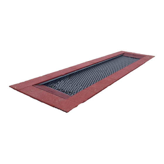
- Page 1 A Assembly Instructions Bouncer Maximus 6 m, art.no 20.02.106 (Fallprotection panel 40 mm) Ramp not included in standard delivery Operator : _________________________________________________________ Site : _____________________________________________________________...
- Page 2 Revision history Revision 0– 2018-01-22 First approved version Revision 0– 2018-06-15 Fallschutzmatten 40 mm / neuer Sicherheitsbereich FH Maintenance instructions All rights reserved. © Copyright 2018 Spogg Sport-Güter GmbH...
-
Page 3: Table Of Contents
Introduction Assembling......................4 Datasheet Bouncer Maximus 6 m, art.no. 20.02.106..............5 Delivery contents (parts list with part numbers)................6 Assembly instructions........................ 11 Maintenance Instructions for Bouncer Maximus 6 m, art.no. 20.02.106........25 Introduction Maintenance......................28 General maintenance information..................... 29 Maintenance timetable........................ 31 Regular maintenance........................32 Monthly maintenance......................... -
Page 4: Introduction Assembling
1 Introduction Assembling General information This equipment should be installed, inspected, maintained and operated in accordance with EN1176-7 guidelines. Before installation work commences, please check that you have all of the equipment and fixation components in the parts list provided (see Tables 3-1 and 3-2). -
Page 5: Datasheet Bouncer Maximus 6 M, Art.no. 20.02.106
2 Datasheet Bouncer Maximus 6 m, art.no. 20.02.106 1. Space requirement: 6,00 m x 1,64 m / including safety zone 9.35 m x 4.99 m. Height of fall 1.0 m 2. Required fall protection: 3. Surface material Description Minimum Maximum... -
Page 6: Delivery Contents (Parts List With Part Numbers)
3 Delivery contents (parts list with part numbers) In words Table 3-1: Delivery contents, in words Pos. Quantity Element / Size Description Frames 3000x320x500x9 Diagonal braces 1616x50x50x3mm Hexagon bolts M10 x 35 Nuts Spring Ø 3,6 x 24 x 170 Bouncer mat Rubber tiles 1000 x 325 x 40... -
Page 7: Table 3-2: Delivery Contents, In Symbols
In symbols Table 3-2: Delivery contents, in symbols Pos. Quantity Symbol Size 3000x320x500x90mm Frame M10 x 120 mm 1000x325x40mm... - Page 8 Pos. Quantity Symbol Size Hally Gally Logo Logo 1000 x 325 x 30 mm...
- Page 9 Required Tools Allen Key 5mm + 3mm Wrench 13mm + 8mm Cutter Knife Drill Paint mixer...
- Page 10 16 inch Square Shovel Notched Trowel Backhoe 10 meter measuring Tape Boards Provided by customer or installer!
- Page 11 Weights Provided by customer or installer!
-
Page 12: Assembly Instructions
4 Assembly instructions... - Page 14 Roll the spring mat Pos. 10 centered in the frame.
- Page 15 Connect all springs. While connecting springs you must simultaneously connect adjacent from each other (left side and then right side). After all springs have been connected, asure that they are equally spaced and not rubbing on the frame.
- Page 16 Connect all springs with the spring mat. We recommend a mounting of approx. 5-8 springs in opposite direction. After all springs are connected check that all springs are hooked evenly and nowhere on the frame.
- Page 18 Turn the frame over to prepare for installing Pos.11 & 13...
- Page 19 Clean the top surface of the frame.
- Page 20 If Tiles (Pos.11) become wet? They must be completely dry before the glueing process begins?
- Page 21 Place Pos.11 onto the frame as shown above.
- Page 22 Tiles (Pos.11) should be flush with the outerside of the frame and have a slight overlap on the inside of the frame Remove the tiles that overlap and then measure the needed length. Measure and cut the tiles assuring that the cut is square!
- Page 23 Place all the tiles on the inside of the frame assuring you know where they were previously placed! Mix the 2 component glue (Pos.13)
- Page 25 Spread the glue (Pos.13) equally using a notched Trowel.
- Page 26 Tiles (Pos.11) should be flush with the outerside of the frame and have a slight overlap on the inside of the frame. Apply weights and boards an allow glue to dry for 24 hours before refilling around the frame.
- Page 27 Post installation checks If the equipment has not been installed safely, you must ensure that the public is prevented from using it. Marking filler depth • Labelling the posts to show the depth of material provided as fall protection (i.e. loose filler). The equipment has not been installed safely in the following cases: •...
-
Page 28: B Maintenance Instructions For Bouncer Maximus 6 M, Art.no. 20.02.106
B Maintenance Instructions for Bouncer Maximus 6 m, art.no. 20.02.106 (Fallprotection panel 40 mm) - Page 29 Revision history Revision 0– 2018-01-22 First approved version Revision 0– 2018-06-15 Fallschutzmatten 40 mm / neuer Sicherheitsbereich FH Maintenance instructions All rights reserved. © Copyright 2018 Spogg Sport-Güter GmbH...
-
Page 30: Introduction Maintenance
5 Introduction Maintenance General information This equipment should be installed, inspected, maintained and operated in accordance with EN1176-7 guidelines. Please note: Providing any necessary repairs are carried out, a piece of play equipment that is inspected regularly cannot become so damaged that it is dangerous. -
Page 31: General Maintenance Information
6 General maintenance information Maintenance intervals Maintenance intervals are based on average use. Please note that more frequent inspections and/or maintenance are required if the play equipment is subject to intensive use. Inspection frequency The frequency of inspections must be based on actual use. Factors that affect frequency include vandalism, location (e.g. - Page 32 6.10 Faults Damages must be repaired as soon as they are detected. If serious defects that affect the safety cannot be repaired straight away, the playground item must be blocked with immediate effect. 6.11 Loose screws Loose screws always cause quality problems and put safety at risk. Therefore, loose screws should always be tightened and checks carried out to ensure that there are no missing screws.
-
Page 33: Maintenance Timetable
7 Maintenance timetable Special advices 7.1.1 Maintenance interval We strongly advise to carry out inspections and maintenance work within the specified periods as use of the equipment, the weather and malicious vandalism cause wear and tear that compromises the safety and function of the equipment. -
Page 34: Regular Maintenance
7.1.4 Faults that compromise function Faults that compromise function should also be repaired immediately. Such faults lower the value of the equipment to the user and encourage malicious vandalism, which may render the equipment less safe. Any damage should be repaired immediately. 8 Regular maintenance : For cleaning underneath the bouncer mat : unhook the springs with a hooked tool. -
Page 38: Monthly Maintenance
9 Monthly maintenance • 10.1 Check the spaces between the equipment and the ground (clearance and height of fall). • 10.2 Check the ground surface in the area with fall protection for hard objects and loose foundations. • 10.3 Check all connecting elements and fittings for wear and tear and tighten if necessary. -
Page 39: Annual Maintenance
• Ascertaining whether there are any changes in equipment safety as a result of repairs that have been carried out or components that have been added or replaced. Annual Maintenance 12 Annual maintenance • 13.1 Ascertaining that the equipment, foundations and surfaces are safe for operation. -
Page 40: Maintenance Printout
13 Maintenance printout Name of item: Bouncer Maximus 6 m______________ / art.no. 20.02.106______________________________________ Location: _________________________________________________________________________________________ Customer or operator: _______________________________________________________________________________ (Town, Town council, Kindergarten) Date of Inspector O.K. Accessibl Blocked Defects Repaired Date inspection Please copy and return once a year after main inspection has been carried out to the manufacturer by fax... -
Page 41: Hand Over Document
The operator has to receive the hand over documents. The complete filled and signed hand over document should be sent to the supplier. art.no.: 20.02.106 Type of item: Bouncer Maximus 6 m Serial number: ___________________________________________________ Customer or operator (Town, Town council, Kindergarten, etc.): _______________________________________________________________ _______________________________________________________________... - Page 42 SPOGG Sport-Güter GmbH · Schulstr. 27 · 35614 Aßlar/Berghausen · www.hally-gally-spielplatzgeraete.de spogg@hallygally-spielplatzgeraete.de _______________________________________________________________ (Signature of operator) (Signature of installation company) (Stamp) Date: ____________________ L:\Montageanleitung englisch\Trampoline Fallschutz 40mm neue Ausführung\Trampolin Maximus 6 und 9 m\20.02.106-eng- 002.odt...
Need help?
Do you have a question about the Bouncer Maximus and is the answer not in the manual?
Questions and answers