Table of Contents
Advertisement
Quick Links
PROPER USE GUIDELINES
Cumulative Trauma Disorders can result from the prolonged use of manually powered hand tools. Hand tools are intended for occasional use and low volume
applications. A wide selection of powered application equipment for extended-use, production operations is available.
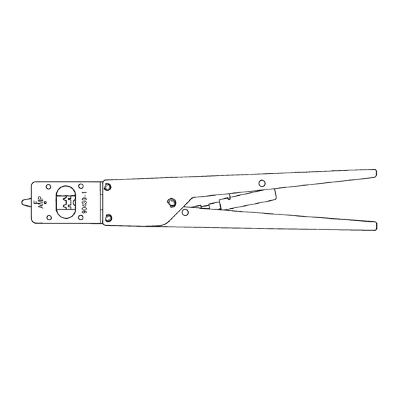
Insulation
Adjustment
AMP
Lever
Anvils
90430–1
CERTI-CRIMP*
Ratchet
Figure 1
1. INTRODUCTION
This instruction sheet covers the use of Hand
Crimping Tool 90430–1 which is designed to crimp
High Density 22 DF loose–piece contacts shown in
Figure 2. Read these instructions thoroughly before
using the tool.
Reasons for reissue are provided in Section 6,
REVISION SUMMARY.
All dimensions on this document are in metric
NOTE
units [with U.S. customary units in brackets].
Figures and illustrations are for identification only
i
and are not drawn to scale.
2. DESCRIPTION
The FRONT OF TOOL, into which the contact is
inserted, has the tool number marked on it (refer to
Figure 1). The BACK OF TOOL (wire side) has the
wire size marked above each crimp section. The tool
features two fixed dies (crimpers), two movable dies
E
2007 Tyco Electronics Corporation, Harrisburg, PA
All International Rights Reserved
TE logo and Tyco Electronics are trademarks.
*Trademark. Other products, logos, and company names used are the property of their respective owners.
Hand Crimping Tool 90430-1
FRONT of TOOL
(Contact Side)
F
Contact Support
Crimpers
Tool Number
TOOLING ASSISTANCE CENTER 1-800-722-1111
PRODUCT INFORMATION 1-800-522-6752
(anvils), two crimp sections with applicable wire–size
markings, a contact support, a locator/wire stop, and
a CERTI–CRIMP ratchet.
The insulation adjustment lever is used to control the
crimp height of the contact insulation barrel. Refer to
Paragraph 4.6, Insulation Crimp Adjustment.
The CERTI–CRIMP ratchet assures full crimping of
the contact. Once engaged, the ratchet will not
release until the handles have FULLY closed.
The crimping dies bottom before the
CAUTION
CERTI-CRIMP ratchet releases. This design
feature assures maximum electrical and tensile
!
performance of the crimp. Do NOT re-adjust the
ratchet.
The locator/wire stop has two functions. First, it
positions the contact between the crimping dies, and
second, it aids in locating the wire in the contact. In
use, it rests in the locator slot. See Figures 2 and 3.
The contact support prevents the contact from
bending during the crimping procedure.
3. CRIMPING PROCEDURE
Refer to the chart in Figure 2 and select wire of the
specified size and insulation diameter. Strip the wire
to the length indicated. Do NOT cut or nick the wire
strands.
Wire Barrel
Insulation Barrel
Wire Strip Length 4.06 [.160]
WIRE
CONTACT
CONTACT
SIZE
INSUL DIA
28-26
0.76-1.02
High Density
g
[.030-.040]
22 DF
24-22
D
For applicable contact part numbers, see Catalog 82068.
Figure 2
This controlled document is subject to change.
For latest revision and Regional Customer Service,
visit our website at
Instruction Sheet
408-9375
15 MAY 07
Rev D
Socket Contact
(Ref)
Shoulder of
Contact
Locator
Slot
CRIMP SECTION WIRE
D
D
SIZE MARKING
26-28
y
22-24
1
of 4
www.tycoelectronics.com
LOC B
Advertisement
Table of Contents

Related Manuals for Tyco Electronics 90430-1


Summary of Contents for Tyco Electronics 90430-1
- Page 1 For latest revision and Regional Customer Service, All International Rights Reserved www.tycoelectronics.com visit our website at TE logo and Tyco Electronics are trademarks. LOC B *Trademark. Other products, logos, and company names used are the property of their respective owners.
- Page 2 Stripped The hand tool is inspected before being shipped; Locator/ Wire however, Tyco Electronics recommends that the tool Wire Stop be inspected immediately upon its arrival at your facility to ensure that the tool has not been damaged during shipment.
- Page 3 Section 3, This inspection requires the use of micrometer with a CRIMPING PROCEDURE. modified anvil as shown in Figure 5. Tyco Electronics recommends use of the modified micrometer (Crimp 4. Hold the wire in place and squeeze the handles Height Comparator RS–1019–5LP) which can be...
- Page 4 Figure 6 should be replaced to HARRISBURG, PA 17105–3608 ensure quality and reliability of the tool. Order replacement parts through your Tyco Electronics 6. REVISION SUMMARY Representative, or call 1–800–526–5142, or send a facsimile of your purchase order to 1–717–986–7605.
Need help?
Do you have a question about the 90430-1 and is the answer not in the manual?
Questions and answers