Table of Contents
Advertisement
Available languages
Available languages
Quick Links
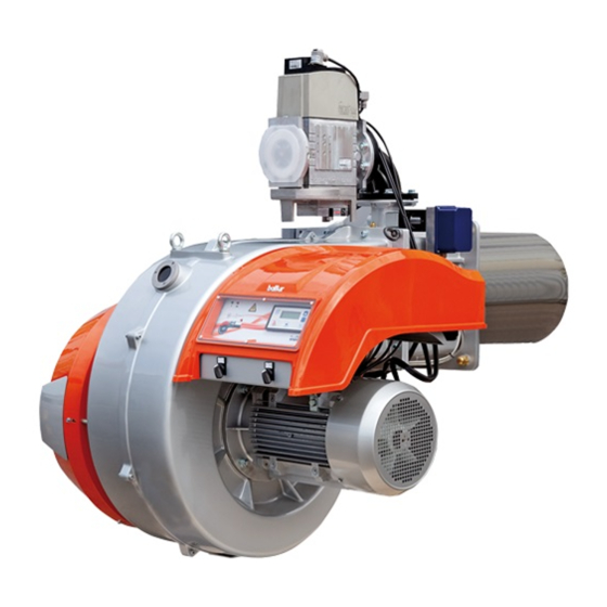
BRUCIATORI GAS BISTADIO PROGRESSIVO / MODULANTE
CON CAMMA ELETTRONICA
TWO-STAGE PROGRESSIVE / MODULATING GAS BURNERS
WITH ELECTRONIC CAM
ITALIANO
TBG 900 ME
Manuale istruzioni per l'installazione, l'uso
IT
e la manutenzione
Instruction manual for
EN
installation, use and maintenance
ISTRUZIONI ORIGINALI (IT)
ORIGINAL INSTRUCTIONS (IT)
0006160267_202106
Advertisement
Chapters
Table of Contents

Related Manuals for baltur TBG 900 ME


Summary of Contents for baltur TBG 900 ME
- Page 1 BRUCIATORI GAS BISTADIO PROGRESSIVO / MODULANTE CON CAMMA ELETTRONICA TWO-STAGE PROGRESSIVE / MODULATING GAS BURNERS WITH ELECTRONIC CAM ITALIANO TBG 900 ME Manuale istruzioni per l'installazione, l'uso e la manutenzione Instruction manual for installation, use and maintenance ISTRUZIONI ORIGINALI (IT)
-
Page 3: Table Of Contents
ITALIANO ITALIANO SOMMARIO Avvertenze per l'uso in condizioni di sicurezza ..............................2 Caratteristiche tecniche ......................................6 Materiale a corredo ......................................6 Targa identificazione bruciatore..................................7 Dati registrazione prima accensione ................................7 Campo di lavoro .......................................8 Descrizione componenti ....................................9 Dimensioni di ingombro ....................................10 Caratteristiche costruttive ....................................11 Caratteristiche tecnico funzionali .................................. -
Page 4: Avvertenze Per L'uso In Condizioni Di Sicurezza
ITALIANO AVVERTENZE PER L'USO IN CONDIZIONI DI taria. • Il bruciatore NON deve essere utilizzato in cicli produttivi e processi SICUREZZA industriali, disciplinati questi ultimi dallo Standard EN 746-2 • La data di produzione dell'apparecchio (mese, anno) sono indicati SCOPO DEL MANUALE sulla targa identificazione bruciatore presente sull'apparecchio. - Page 5 • L’eventuale riparazione dei prodotti dovrà essere effettuata sola- - Tarare la portata di combustibile del bruciatore secondo la poten- mente da un centro di assistenza autorizzato da BALTUR o dal suo za richiesta dal generatore di calore. distributore locale, utilizzando esclusivamente ricambi originali.
- Page 6 ITALIANO AVVERTENZE PARTICOLARI PER L’USO DEL GAS. gia, sole, ecc.) a meno che non sia espressamente previsto; • Verificare che la linea di adduzione e la rampa siano conformi alle - non permettere che l’apparecchio sia usato da bambini o da norme e prescrizioni vigenti.
- Page 7 ITALIANO A CURA DELL'INSTALLATORE - Si raccomanda che il dispositivo di arresto di emergenza sia di • Installare un idoneo sezionatore per ciascuna linea di alimentazione colore rosso e la superficie dietro di esso sia di colore giallo. del bruciatore. - L’azione di emergenza deve essere di tipo mantenuto e richiede- •...
-
Page 8: Caratteristiche Tecniche
ITALIANO CARATTERISTICHE TECNICHE MODELLO TBG 900 ME Potenza termica massima metano 9500 Potenza termica minima metano 1000 mg/kWh ¹) emissioni metano Classe 2 Funzionamento Bistadio progressivo Trasformatore metano 50 hz 8 kV - 30 mA - 230V Stm³/h Portata termica massima metano 1005 Stm³/h... -
Page 9: Targa Identificazione Bruciatore
ITALIANO ¹) EMISSIONI GAS METANO ²) EMISSIONI GAS PROPANO Classi definite secondo la normativa EN 676. Classi definite secondo la normativa EN 676. Classe Emissioni NOx in mg/kWh gas metano Classe Emissioni NOx in mg/kWh gas propano ≤ 170 ≤ 230 ≤... -
Page 10: Campo Di Lavoro
ITALIANO CAMPO DI LAVORO Potenza [kW] IMPORTANTE I campi di lavoro sono ottenuti su caldaie di prova rispondenti alla norma EN676 e sono orientativi per gli accoppiamenti bruciatore-cal- daia. Per il corretto funzionamento del bruciatore le dimensioni della camera di combustione devono essere rispondenti alla normativa vigente;... -
Page 11: Descrizione Componenti
ITALIANO DESCRIZIONE COMPONENTI Testa di combustione Guarnizione Flangia attacco bruciatore Valvola farfalla gas Servomotore azionamento modulazione Display Pressostato aria Servomotore regolazione aria Quadro elettrico Cerniera Motore ventola Convogliatore aria in aspirazione Dispositivo regolazione testa 9 / 28 0006160267_202106... -
Page 12: Dimensioni Di Ingombro
ITALIANO DIMENSIONI DI INGOMBRO Modello TBG 900 ME 1230 1030 1950 Modello E Ø F Ø LØ N Ø TBG 900 ME DN 80 Modello TBG 900 ME 1300 10 / 28 0006160267_202106... -
Page 13: Caratteristiche Costruttive
ITALIANO CARATTERISTICHE COSTRUTTIVE CARATTERISTICHE TECNICO FUNZIONALI Il bruciatore risulta composto da: • Bruciatore di gas conforme alle normative europee EN 676 ed alle • Ventilatore centrifugo per alte prestazioni. Direttive Europee 2006/42/CE; 2014/30/UE; 2014/35/UE; (UE) • Convogliatore aria in aspirazione. 2016/426. -
Page 14: Applicazione Del Bruciatore Alla Caldaia
ITALIANO APPLICAZIONE DEL BRUCIATORE ALLA CALDAIA Per la movimentazione del bruciatore, utilizzare catene o funi certifica- te e adeguate al peso del bruciatore utilizzando i punti di ancoraggio (21). CAUTELA / AVVERTENZE Accertarsi che la testa di combustione abbia lunghezza suffi- ciente per penetrare nel focolare nella quantità... - Page 15 ITALIANO • Dopo aver allineato i fori del gruppo testa con il corpo ventilante, tramite la vite ed il controdado (16), avvitare con le quattro viti con relative rondelle (5) per fissare il corpo testa con il gruppo ventilante. MONTAGGIO RAMPA GAS La rampa gas è...
-
Page 16: Schema Di Principio Rampa Gas
Giunto antivibrante aria (non fornito) Valvola gas di lavoro con regolatore di pressione Valvola di intercettazione manuale (non fornita) Dispositivo controllo tenuta valvole (integrato nell'apparecchiatura) Servomotore regolazione gas A: a cura dell'installatore. B: limite di fornitura baltur. 14 / 28 0006160267_202106... -
Page 17: Collegamenti Elettrici
ITALIANO COLLEGAMENTI ELETTRICI • Tutti i collegamenti devono essere eseguiti con filo elettrico fles- sibile. • Le sezioni dei conduttori non specificati sono da considerarsi di 0,75 mm². • Le linee elettriche devono essere distanziate dalle parti calde. • L’installazione del bruciatore è consentita solo in ambienti con gra- do di inquinamento 2 come indicato nell’allegato M della norma EN 60335-1:2008-07. -
Page 18: Descrizione Del Funzionamento
ITALIANO DESCRIZIONE DEL FUNZIONAMENTO dulante, oppure dal termostato o pressostato del secondo stadio se il bruciatore è in versione due stadi progressivi. Il bruciatore è a funzionamento completamente automatico; chiuden- PRESSOSTATO ARIA do l’interruttore generale e quello del quadro di comando il bruciatore Il pressostato aria ha lo scopo di mettere in sicurezza (blocco) l’appa- viene inserito. - Page 19 ITALIANO L'intervento (apertura di circuito) di qualsiasi pressostato quando il bruciatore è in funzione con fiamma accesa, determina immediata- mente il blocco del bruciatore. Alla prima accensione del bruciatore è indispensabile verificare il cor- retto funzionamento degli stessi. • Verificare l'intervento del rilevatore di fiamma (elettrodo ionizzazio- ne) scollegando il cavo di ionizzazione e inserire il bruciatore.
-
Page 20: Servomotore Comando Serranda Aria
ITALIANO SERVOMOTORE COMANDO SERRANDA ARIA SERVOMOTORE REGOLAZIONE ARIA Indice posizione serranda aria Indice posizione valvole 18 / 28 0006160267_202106... -
Page 21: Schema Di Regolazione Testa Di Combustione E Distanza Disco Elettrodi
ITALIANO SCHEMA DI REGOLAZIONE TESTA DI COMBUSTIONE E DISTANZA DISCO ELETTRODI 1 - Elettrodo ionizzatore Modello 2 - Elettrodo accensione TBG 900 ME 8 - 58 3 - Disco fiamma 4 - Miscelatore 5 - Entrata gas 19 / 28... -
Page 22: Manutenzione
ITALIANO MANUTENZIONE Effettuare almeno una volta all’anno e comunque in conformità alle norme vigenti, l’analisi dei gas di scarico della combustione verificando la correttezza dei valori di emissioni. Al termine della stagione di riscaldamento, eseguire le seguenti ope- razioni: • Pulire le serrande aria, il pressostato aria con presa di pressione ed il relativo tubo se presenti. -
Page 23: Tempi Di Manutenzione
ITALIANO TEMPI DI MANUTENZIONE Descrizione particolare Azione da eseguire TESTA DI COMBUSTIONE CONTROLLO VISIVO, INTEGRITA' CERAMICHE, SMERIGLIATURA ESTREMITA', VERIFICARE DISTANZA, ELETTRODI ANNUO VERIFICARE CONNESSIONE ELETTRICA DISCO FIAMMA CONTROLLO VISIVO INTEGRITA' EVENTUALI DEFORMAZIONI, PULIZIA ANNUO CONTROLLO VISIVO, INTEGRITA' CERAMICHE, SMERIGLIATURA ESTREMITA', VERIFICARE DISTANZA, SONDA DI IONIZZAZIONE ANNUO VERIFICARE CONNESSIONE ELETTRICA... -
Page 24: Vita Attesa
ITALIANO VITA ATTESA La vita attesa dei bruciatori e dei relativi componenti dipende molto dal tipo di applicazione su cui il bruciatore è installato, dai cicli, dalla potenza erogata, dalle condizioni dell’ambiente in cui si trova, dalla frequenza e modalità di manutenzione, ecc. ecc. Le normative relative ai componenti di sicurezza prevedono una vita attesa di progetto espressa in cicli e/o anni di funzionamento. -
Page 25: Istruzioni Per L'accertamento Delle Cause Di Irregolarità Nel Funzionamento E La Loro Eliminazione
ITALIANO ISTRUZIONI PER L'ACCERTAMENTO DELLE CAUSE DI IRREGOLARITÀ NEL FUNZIONAMENTO E LA LORO ELIMINAZIONE IRREGOLARITÁ POSSIBILE CAUSA RIMEDIO Invertire l'alimentazione (lato 230V) del trasformatore di accensione e verificare con Disturbo della corrente di ionizzazione da micro-amperometro analogico. parte del trasformatore di accensione. Sostituire il sensore fiamma. -
Page 26: Schemi Elettrici
ITALIANO SCHEMI ELETTRICI TBG 800 ME - 900 ME - 2000 ME 24 / 28 0006160267_202106... - Page 27 ITALIANO TBG 800 ME - 900 ME - 2000 ME 25 / 28 0006160267_202106...
- Page 28 ITALIANO TBG 800 ME - 900 ME - 2000 ME 26 / 28 0006160267_202106...
- Page 29 ITALIANO TBG 800 ME - 900 ME - 2000 ME 27 / 28 0006160267_202106...
- Page 30 ITALIANO APPARECCHIATURA SENSORE FIAMMA GNYE VERDE / GIALLO RELE’ TERMICO BRUNO FU1÷4 FUSIBILI NERO SPIA BLOCCO ESTERNA / LAMPADA FUNZIONAMENTO RESI- CONNETTORE NERO CON SOVRASTAMPA STENZE AUSILIARIE SPIA DI FUNZIONAMENTO SPIA DI BLOCCO LAMPADA BLOCCO RELE’ TERMICO MOTORE VENTOLA CONTATTORE DI LINEA “CONTATTORE TRIANGOLO“...
- Page 31 ENGLISH ENGLISH SUMMARY Warnings for use in safety conditions ..................................2 Technical specifications ......................................6 Standard accessories .......................................6 Burner identification plate ....................................7 Data recorded during first start-up ..................................7 Operating range .......................................8 Component description ....................................9 Overall dimensions ......................................10 Design characteristics ....................................11 Technical functional characteristics ................................11 Burner connection to the boiler .....................................12 Gas train block diagram ......................................14 Electrical connections ......................................15...
-
Page 32: Warnings For Use In Safety Conditions
ENGLISH WARNINGS FOR USE IN SAFETY ce or know-how. • The equipment use is allowed to such people only if they can have CONDITIONS access to, through a responsible person, the information concerning their safety, surveillance and instructions concerning equipment use. PURPOSE OF THIS MANUAL •... - Page 33 - At the end of the adjustment procedures, check that all the with it directly. Contact only qualified personnel. locking devices of mechanical securing systems are properly • Any product repairs must only be carried out by BALTUR authorised tightened. assistance centres or by its local distributor using only original spare - Make sure that the use and maintenance manual of the burner is parts.
- Page 34 ENGLISH SPECIAL PRECAUTIONS WHEN USING GAS. - The power supply cable for the equipment must not be replaced • Check that the feed line and the train comply with current law and by the user. In case of cable damage, turn the equipment off. To regulations.
- Page 35 ENGLISH TO BE CARRIED OUT BY THE INSTALLER - The emergency activation device must be clearly visible and • Install a suitable disconnecting switch for each burner supply line. easily reachable and actionable in the immediate vicinity of the • The disconnection must be carried out by means of a device com- burner.
-
Page 36: Technical Specifications
ENGLISH TECHNICAL SPECIFICATIONS MODEL TBG 900 ME Maximum natural gas heat power 9500 Minimum natural gas heat power 1000 mg/kWh ¹) natural gas emissions Class 2 Operation Progressive two stage 50 Hz natural gas transformer 8 kV - 30 mA - 230V Stm³/h... -
Page 37: Burner Identification Plate
ENGLISH ¹) NATURAL GAS EMISSIONS ²) PROPANE GAS EMISSIONS Classes defined according to EN 676 standards. Classes defined according to EN 676 standards. Class NOx emissions in mg/kWh natural gas Class NOx emissions in mg/kWh propane gas ≤ 170 ≤ 230 ≤... -
Page 38: Operating Range
ENGLISH OPERATING RANGE Potenza [kW] IMPORTANT The operating ranges are obtained from test boilers corresponding to Standard EN676 and are indicative of the burner-boiler combina- tion. For correct working of the burner, the size of the combustion chamber must correspond to current regulations; if not the manufactu- rers must be consulted. -
Page 39: Component Description
ENGLISH COMPONENT DESCRIPTION Combustion head Seal Burner connection flange Gas throttle valve Modulator activation servomotor Display Air pressure switch Air regulation servomotor Electrical panel Hinge Fan motor Intake air conveyor Combustion head adjustment device 9 / 28 0006160267_202106... -
Page 40: Overall Dimensions
ENGLISH OVERALL DIMENSIONS Model TBG 900 ME 1230 1030 1950 Model E Ø F Ø LØ N Ø TBG 900 ME DN 80 Model TBG 900 ME 1300 10 / 28 0006160267_202106... -
Page 41: Design Characteristics
ENGLISH DESIGN CHARACTERISTICS TECHNICAL FUNCTIONAL CHARACTERISTICS The burner consists of: • Gas burner compliant with the European standards EN 676 and with • Centrifugal fan for high performances. the European Directives 2006/42/CE; 2014/30/UE; 2014/35/UE; • Intake air conveyor. (UE) 2016/426. •... -
Page 42: Burner Connection To The Boiler
ENGLISH BURNER CONNECTION TO THE BOILER For burner handling, use certified chains or ropes suitable for the bur- ner weight using the anchoring points (21). CAUTION / WARNINGS Make sure that the combustion head is long enough to enter the furnace to the extent specified by the boiler manufacturer. - Page 43 ENGLISH • After aligning the holes in the head unit with the ventilating body with the screw and lock nut (16), screw in the four screws with their washers (5) to anchor the head unit onto the ventilating unit. ASSEMBLING THE GAS TRAIN The EN 676 approved gas train is sold separately from the burner.
-
Page 44: Gas Train Block Diagram
Air vibration-proof joint (not supplied) Operating gas valve with pressure regulator Manual shut-off valve (not supplied) Valve tightness control device (integrated in the apparatus) Gas regulation servomotor A: to be carried out by the installer. B: Baltur supply limit. 14 / 28 0006160267_202106... -
Page 45: Electrical Connections
ENGLISH ELECTRICAL CONNECTIONS • It is advisable to make all connections with flexible electric wire. • Conductor cross-sections not specified are to be considered as 0,75 mm². • The power lines must be distanced from the hot parts. • The burner installation is allowed only in environments with pollu- tion degree 2 as indicated in annex M of the EN 60335-1:2008-07 regulation. -
Page 46: Operating Description
ENGLISH OPERATING DESCRIPTION burner reaches a particular value. To ensure correct operation of the air pressure switch you must, with The burner operates fully automatically: it is activated by switching on burner on and in 1st stage, increase its regulation value until the bur- the main switch and the control panel switch. - Page 47 ENGLISH The triggering (opening of the circuit) of any of the pressure switches when the burner is running (flame on) locks out the burner immedia- tely. When first switching on the burner it is essential to check that they work properly. •...
-
Page 48: Air Shutter Control Servomotor
ENGLISH AIR SHUTTER CONTROL SERVOMOTOR AIR REGULATION SERVOMOTOR Air damper position index Valve position index 18 / 28 0006160267_202106... -
Page 49: Diagram For Regulating The Combustion Head And The Electrode Disk Distance
ENGLISH DIAGRAM FOR REGULATING THE COMBUSTION HEAD AND THE ELECTRODE DISK DISTANCE 1 - Ionisation electrode Model 2 - Ignition electrode TBG 900 ME 8 - 58 3 - Flame disc 4 - Mixer 5 - Gas inlet 19 / 28... -
Page 50: Maintenance
ENGLISH MAINTENANCE Analyse combustion gases and check that the emission values are correct at least once a year, in compliance with current law. Carry out the following operations at the end of the heating season: • Clean air dampers, the air pressure switch with pressure port and the relevant pipe, if any. -
Page 51: Maintenance Time
ENGLISH MAINTENANCE TIME Part description Action to be performed COMBUSTION HEAD VISUAL INSPECTION OF THE INTEGRITY OF CERAMICS. TIP GRINDING, CHECK DISTANCE, CHECK ELECTRODES YEARLY ELECTRICAL CONNECTION FLAME DISC INTEGRITY VISUAL CHECK FOR ANY DEFORMATIONS, CLEANING, YEARLY VISUAL INSPECTION OF THE INTEGRITY OF CERAMICS. TIP GRINDING, CHECK DISTANCE, CHECK IONISATION PROBE YEARLY ELECTRICAL CONNECTION... -
Page 52: Expected Lifespan
ENGLISH EXPECTED LIFESPAN The expected lifespan of burners and relevant components depends very much from the type of application on which the burner is installed, from cycles ,of delivered power, from the conditions of the environment in which it is located, from maintenance frequency and mode, etc. Standards about safety components provide for a project expected lifespan expressed in cycles and/or years of operation. -
Page 53: Instructions For Determining The Cause Leading To Irregularities In The Operation And Their Elimination
ENGLISH INSTRUCTIONS FOR DETERMINING THE CAUSE LEADING TO IRREGULARITIES IN THE OPERATION AND THEIR ELIMINATION IRREGULARITY POSSIBLE CAUSE REMEDY Invert the ignition transformer power supply (230V side) and check using an analogue Disturbance to ionization current from the micro-ammeter. ignition transformer. Replace the flame sensor. -
Page 54: Wiring Diagrams
ENGLISH WIRING DIAGRAMS TBG 800 ME - 900 ME - 2000 ME 24 / 28 0006160267_202106... - Page 55 ENGLISH TBG 800 ME - 900 ME - 2000 ME 25 / 28 0006160267_202106...
- Page 56 ENGLISH TBG 800 ME - 900 ME - 2000 ME 26 / 28 0006160267_202106...
- Page 57 ENGLISH TBG 800 ME - 900 ME - 2000 ME 27 / 28 0006160267_202106...
- Page 58 ENGLISH CONTROL BOX BLUE Flame sensor GNYE GREEN / YELLOW THERMAL RELAY BROWN FU1÷4 FUSES BLACK EXTERNAL LOCK INDICATOR LIGHT/ AUXILIARY HEATING BLACK CONNECTOR WITH OVERPRINT ELEMENT OPERATION LAMP OPERATION INDICATOR LIGHT LOCK-OUT WARNING LIGHT FAN MOTOR THERMAL SWITCH RELAY LOCK-OUT LAMP LINE CONTACTOR “TRIANGLE CONTACTOR“...
- Page 60 BALTUR S.P.A. Via Ferrarese, 10 44042 Cento (Fe) - Italy Tel. +39 051-6843711 Fax. +39 051-6857527/28 www.baltur.it info@baltur.it Il presente catalogo riveste carattere puramente indicativo. La casa, pertanto, si riserva ogni possibilità di modifica dei dati tecnici e di quant'altro in esso riportato.