Table of Contents
Advertisement
Available languages
Available languages
Quick Links
ITALIANO
Manuale istruzioni per l'installazione, l'uso e la
Installation, use and maintenance instruction
ISTRUZIONI ORIGINALI (IT)
ORIGINAL INSTRUCTIONS (IT)
TWO-STAGE PROGRESSIVE / MODULATING GAS BURNERS WITH
IT
manutenzione
EN
manual
BRUCIATORI DI GAS A DUE STADI PROGRESSIVI / MODULANTI
CON CAMMA ELETTRONICA
ELECTRONIC CAM
TBG 600 ME
TBG 800 ME
0006081514_201711
Advertisement
Table of Contents

Related Manuals for baltur TBG 600 ME


Summary of Contents for baltur TBG 600 ME
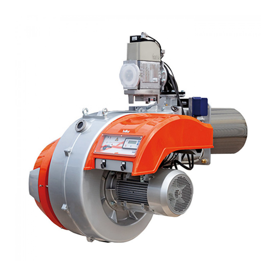
- Page 1 BRUCIATORI DI GAS A DUE STADI PROGRESSIVI / MODULANTI CON CAMMA ELETTRONICA TWO-STAGE PROGRESSIVE / MODULATING GAS BURNERS WITH ELECTRONIC CAM ITALIANO TBG 600 ME Manuale istruzioni per l'installazione, l'uso e la manutenzione TBG 800 ME Installation, use and maintenance instruction...
-
Page 3: Table Of Contents
ITALIANO ITALIANO SOMMARIO Avvertenze per l'uso in condizioni di sicurezza ..............................3 Caratteristiche tecniche ...................................... 6 Materiale a corredo ...................................... 7 Targa identificazione bruciatore ................................... 7 Dati registrazione prima accensione ................................7 Descrizione componenti ....................................9 Dimensioni di ingombro .....................................10 Caratteristiche costruttive .................................. - Page 4 ITALIANO DICHIARAZIONE DI CONFORMITÀ CE0085: DVGW CERT GmbH, Josef-Wirmer Strasse 1-3-53123 Bonn (D) Dichiariamo che i nostri bruciatori ad aria soffiata di combustibili gassosi e misti, serie: BPM...; BGN…; BTG…; TBML...; Comist…; GI…; GI…Mist; Minicomist…; Sparkgas...; TBG..; IB..; TBR... (Variante: … LX, per basse emissioni NOx; -V per inverter, FGR per ricircolazione esterna fumi) rispettano i requisiti minimi imposti dalle Direttive e Regolamenti europei: •...
-
Page 5: Avvertenze Per L'uso In Condizioni Di Sicurezza
ITALIANO AVVERTENZE PER L'USO IN CONDIZIONI DI compresi) le cui capacità fisiche, sensoriali o mentali siano ridotte, oppure con mancanza di esperienza o di conoscenza. SICUREZZA • l'uso dell'apparecchio è consentito a tali persone solo nel caso in cui possano beneficiare, attraverso l'intermediazione di una SCOPO DEL MANUALE persona responsabile, di informazioni relative alla loro sicurezza, Il manuale si propone di contribuire all'utilizzo sicuro del prodotto... - Page 6 • Prima di avviare il bruciatore e almeno una volta all’anno, far • L’eventuale riparazione dei prodotti dovrà essere effettuata effettuare da personale professionalmente qualificato le seguenti solamente da un centro di assistenza autorizzato da BALTUR o dal operazioni: suo distributore locale, utilizzando esclusivamente ricambi originali.
- Page 7 ITALIANO Avvertenze particolari per l’uso del gas. • L’alimentazione elettrica del bruciatore deve prevedere il neutro a • Verificare che la linea di adduzione e la rampa siano conformi alle terra. In caso di controllo della corrente di ionizzazione con neutro norme e prescrizioni vigenti.
-
Page 8: Caratteristiche Tecniche
ITALIANO CARATTERISTICHE TECNICHE MODELLO TBG 600 ME TBG 800 ME POTENZA TERMICA MASSIMA METANO 6000 8000 POTENZA TERMICA MINIMA METANO mg/kWh ¹) EMISSIONI METANO Classe 3 (<80 mg/kWh) Classe 3 (<80 mg/kWh) FUNZIONAMENTO Modulazione elettronica Modulazione elettronica TRASFORMATORE METANO 50 Hz... -
Page 9: Materiale A Corredo
ITALIANO MATERIALE A CORREDO MODELLO TBG 600 ME TBG 800 ME GUARNIZIONE ISOLANTE PRIGIONIERI N°4 M20 N°4 M20 DADI ESAGONALI N°4 M20 N°4 M20 RONDELLE PIANE N°4 Ø20 N°4 Ø20 TARGA IDENTIFICAZIONE BRUCIATORE Logo aziendale Ragione sociale azienda Codice prodotto... - Page 10 ≤ 230 ≤ 120 ≤ 180 ≤ 80 ≤ 140 TBG 600 ME TBG 800 ME mbar kW x 1000 IMPORTANTE I campi di lavoro sono ottenuti su caldaie di prova rispondenti alla norma EN676 e sono orientativi per gli accoppiamenti bruciatore- caldaia.
-
Page 11: Descrizione Componenti
ITALIANO DESCRIZIONE COMPONENTI Testa di combustione Guarnizione Flangia attacco bruciatore Valvola farfalla gas Servomotore regolazione gas Display apparecchiatura Pressostato aria differenziale Servomotore regolazione aria Quadro elettrico Cerniera Motore ventola Convogliatore aria in aspirazione 9 / 28 0006081514_201711... -
Page 12: Dimensioni Di Ingombro
ITALIANO DIMENSIONI DI INGOMBRO Modello TBG 600 ME 1230 1000 2000 TBG 800 ME 1230 1050 2020 Modello E Ø F Ø IØ LØ N Ø TBG 600 ME TBG 800 ME Modello TBG 600 ME 1300 TBG 800 ME... -
Page 13: Caratteristiche Costruttive
ITALIANO CARATTERISTICHE COSTRUTTIVE CARATTERISTICHE TECNICO FUNZIONALI Il bruciatore risulta composto da: • Bruciatore di gas conforme alle normative europee EN 676 ed alle • Parte ventilante in lega leggera d'alluminio. Direttive Europee 2006/42/CE; 2006/95/CE; 97/23/CE; 2004/108/ • Ventilatore centrifugo per alte prestazioni. •... -
Page 14: Applicazione Del Bruciatore Alla Caldaia
ITALIANO APPLICAZIONE DEL BRUCIATORE ALLA CALDAIA MONTAGGIO GRUPPO TESTATA La testa del bruciatore viene imballata separatamente dal corpo bruciatore. Fissare il bruciatore al portellone caldaia nel seguente modo: • Posizionare sul cannotto la guarnizione isolante (13) • Fissare la flangia del polmone (15) alla flangia caldaia (1) tramite i prigionieri, le rondelle e i relativi dadi in dotazione (7). - Page 15 ITALIANO • Dopo aver allineato i fori del gruppo testa con il corpo ventilante, tramite la vite ed il controdado (16), avvitare con le quattro viti con relative rondelle (5) per fissare il corpo testa con il gruppo ventilante. MONTAGGIO RAMPA GAS La rampa gas è...
-
Page 16: Schema Di Principio Rampa Gas
La pressione in uscita, deve essere regolata ad un valore leggermente inferiore a quella massima realizzabile. A CURA DELL’INSTALLATORE LIMITE DI FORNITURA BALTUR Servomotore regolazione aria Valvola di sicurezza Pressostato aria Pressostato gas di minima e controllo fughe gas... -
Page 17: Descrizione Del Funzionamento
ITALIANO DESCRIZIONE DEL FUNZIONAMENTO percentuale di ossido di carbonio (CO) presente nei fumi non superi il valore imposto dalle normative vigenti al momento Il bruciatore è a funzionamento completamente automatico; dell'installazione. chiudendo l’interruttore generale e quello del quadro di comando il •... - Page 18 ITALIANO L'intervento (apertura di circuito) di qualsiasi pressostato quando il bruciatore è in funzione (fiamma accesa) determina immediatamente l'arresto del bruciatore. Alla prima accensione del bruciatore è indispensabile verificare il corretto funzionamento degli stessi. Occorre effettuare questa verifica anche con bruciatore già acceso scollegando il cavo di ionizzazione, l'apparecchiatura si deve portare immediatamente in "blocco".
-
Page 19: Servomotore Comando Serranda Aria
ITALIANO SERVOMOTORE COMANDO SERRANDA ARIA SERVOMOTORE REGOLAZIONE ARIA Indice posizione serranda aria Indice posizione valvole 17 / 28 0006081514_201711... -
Page 20: Schema Di Regolazione Testa Di Combustione E Distanza Disco Elettrodi
ITALIANO SCHEMA DI REGOLAZIONE TESTA DI COMBUSTIONE E DISTANZA DISCO ELETTRODI 1 - Elettrodo ionizzatore Modello 2 - Elettrodo accensione TBG 600 ME 3 - Disco fiamma TBG 800 ME 4 - Miscelatore 18 / 28 0006081514_201711... -
Page 21: Manutenzione
ITALIANO MANUTENZIONE Effettuare almeno una volta all’anno e comunque in conformità alle norme vigenti, l’analisi dei gas di scarico della combustione verificando la correttezza dei valori di emissioni. Al termine della stagione di riscaldamento, eseguire le seguenti operazioni: • Pulire le serrande aria, il pressostato aria con presa di pressione ed il relativo tubo se presenti. -
Page 22: Tempi Di Manutenzione
ITALIANO TEMPI DI MANUTENZIONE Descrizione particolare Azione da eseguire TESTA DI COMBUSTIONE CONTROLLO VISIVO, INTEGRITA CERAMICHE. SMERIGLIATURA ESTREMITA, VERIFICARE ELETTRODI ANNUO DISTANZA, VERIFICARE CONNESSIONE ELETTRICA DISCO FIAMMA CONTROLLO VISIVO INTEGRITA EVENTUALI DEFORMAZIONI, PULIZIA ANNUO CONTROLLO VISIVO, INTEGRITA CERAMICHE. SMERIGLIATURA ESTREMITA, VERIFICARE SONDA DI IONIZZAZIONE ANNUO DISTANZA, VERIFICARE CONNESSIONE ELETTRICA... -
Page 23: Vita Attesa
ITALIANO VITA ATTESA La vita attesa dei bruciatori e dei relativi componenti dipende molto dal tipo di applicazione su cui il bruciatore è installato, dai cicli della potenza erogata, dalle condizioni dell’ambiente in cui si trova, dalla frequenza e modalità di manutenzione, ecc. ecc. Le normative relative ai componenti di sicurezza, prevedono una vita attesa di progetto espressa in cicli e/o anni di funzionamento. -
Page 24: Istruzioni Per L'accertamento Delle Cause Di Irregolarità Nel Funzionamento E La Loro Eliminazione
ITALIANO ISTRUZIONI PER L'ACCERTAMENTO DELLE CAUSE DI IRREGOLARITÀ NEL FUNZIONAMENTO E LA LORO ELIMINAZIONE IRREGOLARITÁ POSSIBILE CAUSA RIMEDIO Invertire l'alimentazione (lato 230V) del trasformatore di accensione e verificare Disturbo della corrente di ionizzazione con micro-amperometro analogico. da parte del trasformatore di Sostituire il sensore fiamma. -
Page 25: Schemi Elettrici
ITALIANO SCHEMI ELETTRICI TBG 480 ÷ 2000 ME 23 / 28 0006081514_201711... - Page 26 ITALIANO TBG 480 ÷ 2000 ME 24 / 28 0006081514_201711...
- Page 27 ITALIANO TBG 480 ÷ 2000 ME 25 / 28 0006081514_201711...
- Page 28 ITALIANO TBG 480 ÷ 2000 ME 26 / 28 0006081514_201711...
- Page 29 ITALIANO APPARECCHIATURA FOTORESISTENZA / ELETTRODO DI IONIZZAZIONE / GNYE VERDE / GIALLO FOTOCELLULA UV BRUNO RELE’ TERMICO NERO FU1÷4 FUSIBILI CONNETTORE NERO CON SOVRASTAMPA SPIA BLOCCO ESTERNA / LAMPADA FUNZIONAMENTO RESISTENZE AUSILIARIE SPIA DI FUNZIONAMENTO “SPIA DI BLOCCO“ LAMPADA BLOCCO RELE’ TERMICO MOTORE VENTOLA CONTATTORE DI LINEA “CONTATTORE TRIANGOLO“...
- Page 31 ENGLISH ENGLISH INDEX Instructions for use in safe conditions ................................3 Technical specifications ...................................... 6 Supplied material ......................................7 Burner identification plate .................................... 7 First start up recording data ..................................7 Component description ....................................9 Overall dimensions ....................................10 Design characteristics ....................................11 Technical functional characteristics ................................
- Page 32 ENGLISH DECLARATION OF CONFORMITY CE0085: DVGW CERT GmbH, Josef-Wirmer Strasse 1-3-53123 Bonn (D) We hereby declare under our own responsibility, that our blown air burners fired by gas and dual fuel, series: BPM...; BGN…; BTG…; TBML...; Comist…; GI…; GI…Mist; Minicomist…; Sparkgas...; TBG..; IB..; TBR... (Variant: …...
- Page 33 ENGLISH INSTRUCTIONS FOR USE IN SAFE the device. • This appliance should only be used for the purpose it has been CONDITIONS designed for. Any other use is to be considered improper and therefore dangerous. PURPOSE OF THE MANUAL • The equipment must be installed in accordance with current The manual purpose is to contribute to the safe use of the product, regulations, following the manufacturer’s instructions and by indicating the conduct and behaviour required to prevent alterations...
- Page 34 Contact only qualified personnel. - Check the regulation and safety devices are working properly. • Any product repairs must only be carried out by BALTUR authorised - Check for the correct operation of the combustion products assistance centres or its local retailer using only original spare exhaust duct.
- Page 35 ENGLISH Special instructions for using gas. • The use of any components that use electricity means that certain • Check that the feed line and the train comply with current standards fundamental rules have to followed, including the following: and regulations. - do not touch the equipment with parts of the body that are wet •...
- Page 36 ENGLISH TECHNICAL SPECIFICATIONS MODEL TBG 600 ME TBG 800 ME MAXIMUM NATURAL GAS HEAT POWER 6000 8000 MINIMUM NATURAL GAS HEAT POWER mg/kWh ¹) NATURAL GAS EMISSIONS Class 3 (<80 mg/kWh) Class 3 (<80 mg/kWh) OPERATION Electronic modulation Electronic modulation...
- Page 37 ENGLISH SUPPLIED MATERIAL MODEL TBG 600 ME TBG 800 ME INSULATING SEAL STUD BOLTS No. 4 M20 No. 4 M20 HEXAGONAL NUTS No. 4 M20 No. 4 M20 FLAT WASHERS No. 4 Ø20 No. 4 Ø20 BURNER IDENTIFICATION PLATE Company logo...
- Page 38 ≤ 230 ≤ 120 ≤ 180 ≤ 80 ≤ 140 TBG 600 ME TBG 800 ME mbar kW x 1000 IMPORTANT The operating ranges are obtained from test boilers corresponding to Standard EN676 and are indicative of the burner-boiler combination.
- Page 39 ENGLISH COMPONENT DESCRIPTION Combustion head Seal Burner connection flange Gas throttle valve Gas regulation servomotor Equipment display Air pressure switch differential Air regulation servomotor Electrical panel Hinge Fan motor Intake air conveyor 9 / 28 0006081514_201711...
- Page 40 ENGLISH OVERALL DIMENSIONS Model TBG 600 ME 1230 1000 2000 TBG 800 ME 1230 1050 2020 Model E Ø F Ø IØ LØ N Ø TBG 600 ME TBG 800 ME Model TBG 600 ME 1300 TBG 800 ME 1300...
- Page 41 ENGLISH DESIGN CHARACTERISTICS TECHNICAL FUNCTIONAL CHARACTERISTICS The burner consists of: • Gas burner compliant with European Standards EN 676 and • Ventilating part in light aluminium alloy. European Directives 006/42/EC; 2006/95/EC; 97/23/EC; 2004/108/ • Centrifugal fan for high performances. • Intake air conveyor. •...
- Page 42 ENGLISH BURNER CONNECTION TO THE BOILER ASSEMBLING THE HEAD UNIT The burner head is packaged separately from the body of the burner. Anchor the burner to the boiler door as follows: • Position the insulating seal -13 on the sleeve. •...
- Page 43 ENGLISH • After aligning the holes in the head unit with the ventilating body using the screw and lock nut -16, screw in the 4 screws with their washers -5 to anchor the head unit to the ventilating unit. ASSEMBLING THE GAS TRAIN The EN 676 approved gas train is sold separately from the burner.
- Page 44 The delivery pressure must be adjusted to a level slightly below the maximum obtainable. RESPONSIBILITY OF THE INSTALLER LIMITS ON BALTUR SUPPLY Air regulation servomotor Safety valve Air pressure switch Minimum gas pressure switch and gas leak control...
- Page 45 ENGLISH OPERATING DESCRIPTION The air pressure switch stops the equipment operation if air pressure is not at the expected value. Burner operation is fully automatic; it starts up by enabling the main The pressure switch must therefore be adjusted so that it is triggered switch and the control panel switch.
- Page 46 ENGLISH The triggering (opening of the circuit) of any of the pressure switches when the burner is running (flame on) causes the burner to stop immediately. It is essential to check that the burner is functioning correctly at the time of the first ignition. This test should also be performed with the burner already on.
- Page 47 ENGLISH AIR SHUTTER CONTROL SERVOMOTOR AIR REGULATION SERVOMOTOR Air damper position index Valves position index 17 / 28 0006081514_201711...
- Page 48 ENGLISH DIAGRAM FOR REGULATION OF COMBUSTION HEAD AND ELECTRODE DISK DISTANCE 1 - Ionisation electrode Model 2 - Ignition electrode TBG 600 ME 3 - Flame disk TBG 800 ME 4 - Mixer 18 / 28 0006081514_201711...
- Page 49 ENGLISH MAINTENANCE Analyse combustion gases and check that the emission values are correct at least once a year, in compliance with current law. Carry out the following operations at the end of the heating season: • Clean air dampers, the air pressure switch with pressure port and the relevant pipe (if fitted).
- Page 50 ENGLISH MAINTENANCE TIME Part description Action to be performed COMBUSTION HEAD VISUAL CHECK, CERAMIC INTEGRITY. END GRINDING, CHECK DISTANCE, CHECK ELECTRICAL ELECTRODES YEARLY CONNECTION FLAME DISK INTEGRITY VISUAL CHECK FOR ANY DEFORMATIONS, CLEANING YEARLY VISUAL CHECK, CERAMIC INTEGRITY. END GRINDING, CHECK DISTANCE, CHECK ELECTRICAL IONISATION PROBE YEARLY CONNECTION...
- Page 51 ENGLISH EXPECTED LIFESPAN The expected lifespan of burners and relevant components depends very much from the type of application on which the burner is installed, from cycles of delivered power, from the conditions of the environment in which it is located, from maintenance frequency and mode, etc. Standards about safety components provide for a project expected lifespan expressed in cycles and/or years of operation.
- Page 52 ENGLISH TROUBLESHOOTING INSTRUCTIONS ANOMALY POSSIBLE CAUSE REMEDY Invert the ignition transformer power supply (230V side) and check using an Disturbance to ionisation current from analogue micro-ammeter. the ignition transformer. Replace flame sensor. Flame sensor (ionisation probe) Correct the position of the flame sensor, inefficient.
- Page 53 ENGLISH WIRING DIAGRAMS TBG 480 ÷ 2000 ME 23 / 28 0006081514_201711...
- Page 54 ENGLISH TBG 480 ÷ 2000 ME 24 / 28 0006081514_201711...
- Page 55 ENGLISH TBG 480 ÷ 2000 ME 25 / 28 0006081514_201711...
- Page 56 ENGLISH TBG 480 ÷ 2000 ME 26 / 28 0006081514_201711...
- Page 57 ENGLISH EQUIPMENT BLUE PHOTORESISTOR / IONISATION ELECTRODE / UV GNYE GREEN / YELLOW PHOTOCELL BROWN THERMAL RELAY BLACK FU1÷4 FUSES BLACK CONNECTOR WITH OVERPRINT EXTERNAL LOCK INDICATOR LIGHT/ AUXILIARY HEATING ELEMENT OPERATION LAMP OPERATION INDICATOR LIGHT “LOCK-OUT INDICATOR LIGHT“ FAN MOTOR THERMAL SWITCH RELAY LOCK-OUT LAMP LINE CONTACTOR “TRIANGLE CONTACTOR“...
- Page 60 .BALTUR S.P.A 10 ,Via Ferrarese Cento (Fe) - Italy 44042 6843711-051 39+ .Tel 28/6857527-051 39+ .Fax www.baltur.it info@baltur.it Il presente catalogo riveste carattere puramente indicativo. La casa, pertanto, si riserva ogni possibilità di modifica dei dati tecnici e di quant'altro in esso riportato.
Need help?
Do you have a question about the TBG 600 ME and is the answer not in the manual?
Questions and answers