baltur TBG 45 PN Manual User Instructions
Hide thumbs
Also See for TBG 45 PN:
- Manual instructions for use (98 pages) ,
- Instructions for use manual (124 pages)
Table of Contents
Advertisement
Available languages
Available languages
Quick Links
Advertisement
Chapters
Table of Contents

Subscribe to Our Youtube Channel
Related Manuals for baltur TBG 45 PN


Summary of Contents for baltur TBG 45 PN
- Page 1 Manual user instructions. Manuale istruzioni per l'uso. TBG 45 PN TBG 60 PN BRUCIATORI DI GAS A DUE STADI PROGRESSIVI / MODULANTI CON REGOLAZIONE PNEUMATICA ISTRUZIONI ORIGINALI (IT) ORIGINAL INSTRUCTIONS (IT) 0006081364_201209...
-
Page 3: Table Of Contents
Tel. 051.684.37.11 Fax 051.685.75.27/28 (International Tel. ++39.051.684.37.11 - Fax ++39.051.683.06.86) • L’alimentazione elettrica dell’impianto deve essere disinserita prima di iniziare i lavori. http://www.baltur.it - http://www.baltur.com - E-MAIL info@baltur.it • Se i lavori non sono eseguiti correttamente si rischiano incidenti pericolosi. Dichiarazione di Conformità... - Page 4 L’eventuale riparazione dei prodotti dovrà essere effettuata solamente vigenti. da un centro di assistenza autorizzato dalla BALTUR utilizzando d) Verifi care la funzionalità dei dispositivi di regolazione e di sicurezza. esclusivamente ricambi originali. Il mancato rispetto di quanto sopra, può...
- Page 5 AVVERTENZE PER L’UTENTE PER L’USO IN SICUREZZA DEL BRUCIATORE • Per la prima messa in funzione dell’apparecchio far effettuare ALIMENTAZIONE ELETTRICA da personale professionalmente qualificato le seguenti verifiche: • La sicurezza elettrica dell’apparecchio è raggiunta soltanto quando lo a) il controllo della tenuta nel tratto interno ed esterno dei tubi di adduzione stesso è...
-
Page 6: Caratteristiche Tecniche
CARATTERISTICHE TECNICHE TBG 45PN TBG 60PN MAX kW POTENZA TERMICA MIN kW FUNZIONAMENTO Bistadio progressivo/modulante EMISSIONI NOx mg/kWh < 80 (Classe III secondo EN 676) 0,50 0,75 MOTORE r.p.m. 2730 2800 POTENZA ELETTRICA ASSORBITA* 0,68 0,94 FUSIBILE di linea 4A / 400 V TRASFORMATORE D’ACCENSIONE 26 kV - 40 mA - 230/240 V - 50/60 Hz TENSIONE... - Page 7 B1 B6 Ø Ø TBG 45 PN 550 270 280 435 325 160 920 140 300 137 133 215 200 245 M12 145 182 12 42,5 73,6 TBG 60 PN 550 270 280 455 325 160 920 140 300 156 152 260 225 300 M12 160 194 12 79 45,5 La foratura portellone N1 permette l’inserimento diretto del cannotto bruciatore e del tubino pressione in camera combustione.
-
Page 8: Linea Di Alimentazione
CAMPO DI LAVORO TBG P TBG 45P TBG P TBG 45P TBG 45P TBG P TBG 45 mbar m /h(Metano) m /h(G.P.L.) I campi di lavoro sono ottenuti su caldaie di prova rispondenti alla norma EN676 e sono orientativi per gli accoppiamenti bruciatore-caldaia. Per il corretto funzionamento del bruciatore le dimensioni della camera di combustione devono essere rispondenti alla normativa vigente;... - Page 9 APPLICAZIONE DEL BRUCIATORE ALLA CALDAIA Posizionare sul cannotto la guarnizione isolante 3 interponendo la corda 2 tra flangia e guarnizione. allentare le viti “6”, adeguare la posizione della flangia di attacco “5” in modo che la testata di combustione penetri nel focolare della lunghezza consigliata dal costruttore del gene- ratore.
-
Page 10: Collegamenti Elettrici
COLLEGAMENTI ELETTRICI La linea di alimentazione trifase deve essere provvista di interrutto- re con fusibili. E’ inoltre richiesto dalle Normative vigenti un interrut- tore sulla linea di alimentazione del bruciatore, posto all’esterno del locale caldaia in posizione facilmente raggiungibile. Per i collegamenti elettrici (linea e termostati) attenersi allo schema elettrico allegato. -
Page 11: Descrizione Del Funzionamento - Descrizione Del Funzionamento Della Modulazione
DESCRIZIONE DEL FUNZIONAMENTO della portata di gas fino al valore massimo regolato. Nel caso di assenza fiamma, l’apparecchiatura si arresta in “bloc- Alla chiusura dell’interruttore generale e dell’interruttore I/O (22) co di sicurezza” (accensione led 20) entro 3 secondi dall’apertu- del quadro elettrico, se i termostati sono chiusi, la tensione rag- ra della valvola principale. -
Page 12: Apparecchiatura Di Comando E Controllo Bruciatori A Gas Lme
APPARECCHIATURA DI COMANDO E CONTROLLO BRUCIATORI A GAS LME ... Funzionamento, indicazioni, diagnstica Il pulsante di sblocco «EK...» è l’elemento principale per poter accedere a tutte le funzioni di ROSSO diagnostica (attivazione e disattivazione), oltre a sbloccare il dispositivo di comando e controllo. Il «LED»... - Page 13 Diagnosi della causa di malfunzionamento e blocco In caso di blocco bruciatore nel pulsante di sblocco sarà fissa la luce rossa. Premendo per più di 3 sec. la fase di diagnosi verrà attivata (luce rossa con lampeggio rapido), nella tabella sottostante viene riportato il significato della causa di blocco o malfunzionamento in funzione del numero di lampeggi (sempre di colore rosso).
- Page 14 AGK25... Resistenza PTC Schema dei collegamenti e controllo della sequenza di lavoro dell’apparec- AL Messaggio di errore (allarme) chiatura LME22… BCI Interfaccia di Comunicazione del Bruciatore BV... Valvola del Combustibile CPI Indicatore di Posizione Chiusa Dbr.. Ponticello cablaggio EK.. Pulsante di reset del blocco remoto (interno) EK2 Pulsante di reset del blocco remoto ION Sonda di Ionizzazione FS Segnale di Fiamma...
-
Page 15: Accensione E Regolazionea Gas Metano
ACCENSIONE E REGOLAZIONE manualmente il teleruttore, che il motore giri nel senso corretto, se necessario, scambiare di posto ai due cavi della linea che A GAS METANO alimenta il motore trifase per invertire il senso di rotazione. • Per la regolazione iniziale ricorrere al funzionamento in modalità •... - Page 16 E’ indispensabile verificare con l’apposito strumento che la per essere chiuso in lavoro (pressione aria insufficiente) percentuale di ossido di carbonio (CO) presente nei fumi non l’apparecchiatura esegue il suo ciclo ma non si inserisce il superi il valore imposto dalla normativa vigente al momento trasformatore d’accensione e non si aprono le valvole del gas e dell’installazione.
- Page 17 preferibile, per la piccola fiamma, limitare la quantità di aria allo stretto indispensabile per avere un’accensione sicura anche nei casi più impegnativi. ISTRUZIONI PER IL FUNZIONAMENTO IN MODALITA’ MANUALE DEL BRUCIATORE E’ possibile effettuare il controllo della combustione su tutto il range di modulazione mediante regolazione manuale del funzionamento.
-
Page 18: Regolazione Dell' Aria Sulla Testa Di Combustione
SCHEMA REGOLAZIONE ELETTRODI / SONDA IONIZZAZIONE TBG 45PN TBG 60PN Legenda: 1- Elettrodo ionizzazione 2- Elettrodo accensione 3- Disco fiamma TBG 45PN 4- Miscelatore TBG 60PN 5- Tubo mandata gas REGOLAZIONE DELL’ ARIA SULLA TESTA DI COMBUSTIONE In pratica si deve iniziare la regolazione con il dispositivo che La testa di combustione è... - Page 19 Valore indicato BRUCIATORE REGOLAZIONE CAMME SERVOMOTORE dall’indice 4 SQN72.6A4A20 PER TBG ...PN TBG 45PN 3 ÷31 0 ÷ 3,2 TBG 60PN 6÷ 34 0 ÷ 3,2 P E R N O I N S E R Z I O N E E D ESCLUSIONE ACCOPPIAMENTO CAMME REGOLABILI MOTORE - ALBERO CAMME...
-
Page 20: Manutenzione
MANUTENZIONE Effettuare periodicamente l’analisi dei gas di scarico della combu- stione verificando la correttezza dei valori di emissioni. Sostituire periodicamente il filtro del gas quando è sporco. Verificare che tutti i componenti della testa di combustione siano in buono stato, non deformati dalla temperatura e privi di impurità o depositi derivanti dall’ambiente di installazione o da una cattiva combustione, controllare l’efficienza degli elettrodi. -
Page 21: Predisposizione Per Attacco Rampa Verso L'alto - Dispositivo Di Regolazione Manuale Pressione Gas In Testa
PREDISPOSIZIONE PER ATTACCO DISPOSITIVO DI REGOLAZIONE RAMPA VERSO L'ALTO MANUALE PRESSIONE GAS IN TESTA Se si desidera portare il lato di ingresso rampa verso l’alto, prima di Per un corretto funzionamento delle valvole proporzionali in tutto applicare il bruciatore alla caldaia, seguire la procedura seguente. il range di modulazione è... -
Page 22: Istruzioni Montaggio Riduzioni Per Gpl
ISTRUZIONI MONTAGGIO In alcune particolari applicazioni, nel caso si verificassero pulsazioni di fiamma durante il funzionamento del bruciatore RIDUZIONI PER GPL con gas naturale, si consiglia di utilizzare le riduzioni previste per il combustibile GPL. Nel caso di funzionamento con combustibile GPL inserire le apposite riduzioni fornite a corredo del bruciatore. -
Page 23: Istruzioni Per L'accertamento Delle Cause Di Irregolaritá Nel Funzionamento E Loro Eliminazione
ISTRUZIONI PER L’ACCERTAMENTO DELLE CAUSE DI IRREGOLARITÁ NEL FUNZIONAMENTO E LORO ELIMINAZIONE IRREGOLARITÁ CAUSA POSSIBILE RIMEDIO ) Disturbo della corrente di Ionizzazione da 1) Invertire l’alimentazione (lato 230V) del L’apparecchio va in “blocco” con parte del trasformatore di accensione. trasformatore di accensione e verificare con f i a m m a ( l a m p a d a r o s - micro-amperometro analogico s a a c c e s a ) . -
Page 24: Schema Elettrico
SCHEMA ELETTRICO 22 / 24 0006081364_201209... - Page 25 23 / 24 0006081364_201209...
- Page 26 CORRENTE DI IONIZZAZIONE MINIMA 3µA SIGLA SOLO PER TARATURA APPARECCHIATURA ** A RICHIESTA CONTROLLO TENUTA VALVOLA ELETTRODO DI IONIZZAZIONE DIN / IEC RELE’ TERMICO GNYE VERDE / GIALLO FUSIBILE SPIA BLOCCO ESTERNA BRUNO NERO SPIA DI FUNZIONAMENTO CONNETTORE NERO CON SOVRASTAMPA SPIA DI BLOCCO RELE’...
- Page 27 Via Ferrarese 10 - 44042 CENTO (Ferrara) ITALIA • Read carefully the instructions before starting the burner and service it. Tel. 051.684.37.11 Fax 051.685.75.27/28 (International Tel. ++39.051.684.37.11 - Fax ++39.051.683.06.86) • The system electric feeding must be disconnected before starting working on it. http://www.baltur.it - http://www.baltur.com - E-MAIL info@baltur.it • If the works are not carried out correctly it is possible to cause dangerous accidents. Declaration of Conformity We declare that our products BPM...; BGN…; BT…; BTG…; BTL…; TBML...; Comist…;...
- Page 28 • If there is any fault or if the equipment is not working properly, de-ac- b) Adjust the combustion air fl ow to obtain combustion yield of at least tivate the equipment and do not attempt to repair it or tamper with it the minimum set by current regulations. directly. In such case get in touch with only qualifi ed technicians. Any c) Carry out a check on combustion to ensure the production of no- product repairs must only be carried out by BALTUR authorised assi- xious or polluting unburnt gases does not exceed limits permitted stance centres using only original spare parts. Failure to act as above by current regulations. may jeopardise the safety of the equipment. To ensure the effi ciency d) Check the adjustment and safety devices are working properly. and correct working of the equipment, it is essential to have periodic e) Check the effi ciency of the combustion products exhaust duct. maintenance carried out by qualifi ed technicians following the manufac- turer’s instructions.
- Page 29 WARNING NOTES FOR THE USER HOW TO USE THE BURNER SAFELY Special warning notes when using gas ELECTRICAL SUPPLY • Have qualifi ed technicians check the following: • The equipment is electrically safe only when it is correctly connected to an effi cient ground connection carried out in accordance with current safety a) that the feed line and the train comply with current law and regulations. It is necessary to check this essential safety requirement. regulations. If in doubt, call for a careful electrical check by a qualifi ed technicians, b) that all the gas connections are properly sealed.
-
Page 30: Technical Data
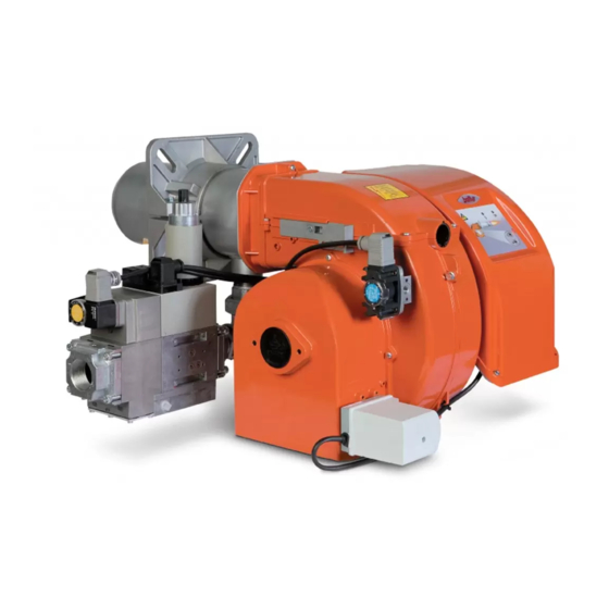
TECHNICAL DATA TBG 45PN TBG 60PN MAX kW THERMIC CAPACITY MIN kW OPERATION Two-stage progressive/ modulating versions NOx EMMISION < 80 (Classe III secondo EN 676) mg/kWh 0,50 0,75 MOTOR 2730 2800 r.p.m. ABSORBED ELECTRICAL POWER* 0,67 0,94 line fuse 4A / 400V A / 400 V IGNITION TRANSFORMER 26 kV - 40 mA - 230/240 V - 50/60 Hz VOLTAGE 1N ~ 230 V ±10%- 50 Hz 3N ~ 400 V ±10%- 50 Hz PROTECTION RATING IP 44 FLAME DETECTOR IONIZATION PROBE NOISE** WEIGHT Natural Gas (G 20) 45,3 60,3 m³n/h FLOW RATE... - Page 31 OVERALL DIMENSIONS 1) Combustion head 6) Gas train connector flange 7) Electrical panel 2) Gasket 8) Motor 3) Burner attachment flange 9) Air adjustment servomotor 4) Combustion Head adjustment device 10) Air pressure switch 5) Cover MOD. B1 B6 Ø Ø TBG 45 PN 550 270 280 435 325 160 920 140 300 137 133 215 200 245 M12 145 182 12 42,5 73,6 TBG 60 PN 550 270 280 455 325 160 920 140 300 156 152 260 225 300 M12 160 194 12 79 45,5...
-
Page 32: Power Supply Line
WORKING FIELD TBG 45PN / 60PN TBG P TBG 45P TBG P TBG 45P TBG 45P TBG P TBG 45 mbar m /h(Metano) m /h(G.P.L.) The working fields are obtained from test boilers corresponding to the standard EN267 and are indicatively for the combination burner-boiler. For correct working of the burner the size of the combustion chamber must correspond to current regulations; if not the manufacturers must be consulted. POWER SUPPLY LINE The gas supply scheme is shown in the diagram below. The gas train is certified in accordance with regulations EN 676 and is supplied separately from the burner. A manual shut off valve and anti-vibration joint must be installed upstream of the gas valve, as shown in the diagram. GENERAL GAS BURNER SYSTEM Gas train supplied by the manufacturer The job of the installer 1) Manual shut off valve 7) Valves seal control device (obligatory for burner with maximum nominal thermal out-put over 1200 kW) - Page 33 APPLICATION OF BURNER TO BOILER - Adjust the position of connector flange 5 by loosening the screws 6 so that the combustion head penetrates the advised amount into the combustion chamber as recommended by the genertor’s manufacturer. Following the drawing, connect the tube on the attachment on the flange and fix with the screw - Position the seal insulation 3 on the tube unit inserting cord 2 between flange and seal. - Fasten the Combustion Head unit 4 to the boiler 1 by means of the stud bolts, washers and the nuts provided 7. isolate completely, with suitalbe materia the space between the burner tube and the hole on the refractory material inside the boiler’s shutter.
-
Page 34: Wiring Diagram
WIRING DIAGRAM The three-phase power supply line must have a switch with fuses. The regulations further require a switch on the burner’s power sup- ply line, outside the boiler room and in an easily accessed position. For the electrical connections (line and thermostats), follow the wiring diagram enclosed. To carry out the connection of the burner to the power supply line proceed as follows: - Remove the lid by unscrewing the 4 screws (1) in figure 1. In this way the burner’s electrical panel can be accessed. - Slacken screws (2) and, after removing the cable float plate (3), pass the two 7 and 4 pole plugs through the hole (see figu- re 2). In the case of a three-phase burner, connect the power supply cables (4) to the contactor, fix the ground cable (5) and tighten its cable holder. Fig. 2 - Reposition the cable float plate as in figure 3. Turn the cam (6) so that the float exerts sufficient pressure on the two cables, then tighten the screws that fasten the cable float. Finally, con- nect the two 7 and 4-pole plugs. the housings for the cables for the 7 and 4-pole plugs are respectively for cable Ø 9.5-10 mm and Ø 8.5-9 mm, this to make sure the protection rating of IP 44 (IEC EN 60529) for the electrical panel. - To reclose the electrical panel lid, tighten the 4 screws (1) with a torque of about 5 Nm to ensure the correct seal. only qualified technicians may open the burner’s electrical panel. - Page 35 DESCRIPTION OF OPERATION DESCRIPTION OF MODULATION WORKING When the main switch and the I/O switch (22) on the electrical When the burner is running at minimum capacity, if the modulation panel are closed. If the thermostats are closed, voltage will reach probe allows, (adjusted to a temperature or pressure value gre- the command and control device, which starts up the burner (led ater than that in the boiler) the air adjustment servo motor starts 19 comes on). to turn causing gradual increase in combustion air supply and, This turns on the fan motor for preventilation of the combustion consequently also of gas, up to the maximum supply for which chamber. The ignition transformer then comes on, and 2 seconds the burner has been set. The increase in the fan air pressure is...
-
Page 36: Gas Burner Control Device Gas Lme
GAS BURNER CONTROL DEVICE GAS LME ... Operation, indication, diagnostics Lockout reset button (EK) is the key operating element for resetting the burner control and for activating / deactivating the diagnostics func-tions. The multicolor signal lamp (LED) in the lockout reset button is the key indicating element for YELLOW visual diagnostics and interface diagnostics. GREEN Both lockout reset button (EK) and signal lamp (LED) are located under the transparent cover of the lockout reset button. There are 2 diagnostics choices: 1. Visual diagnostics: Operational status indication or diagnostics of the cause of fault. 2. Interface diagnostics: With the help of the OCI400 interface adapter and the ACS410 PC software or flue gas analyzers of different makes. Visual diagnostics: In normal operation, the different operating states are indicated in the form of color codes according to the color code table given below. After lockout, the red fault signal lamp LED will remain steady on. In that condition, visual diagnostics of the cause of fault according to the error code table can be acti-vated by pressing the lockout reset button for more than 3 seconds. Pressing the reset button again for at least 3 seconds, interface diagnostics will be activated. Interface diagnostics works only if the AGK20… lockout reset button extension is not fitted. If, by accident, interface diagnostics has been activated, in which case the slightly red light of the signal lamp LED flickers, it can be deactivated by pressing again the lockout reset button for at least 3 seconds. The instant of switching over is indicated by a yellow light pulse. Operational status indication During startup, status indication takes place according to the following table: Color code table for multicolor signal lamp (LED) Status Color code Color Waiting time «tw», other waiting states... - Page 37 After lockout. the red fault signa llamp will remaln steady on. In thal conditio visual diagnostics of the cause of fault acccording to the error code table can be activated by presslng the lockout reset button for more than 3 seconds. Pressing the reset button again for at least 3 seconds, interface diagnostics will be activated The followlng sequence activates the diagnostics of Ihe cause of fault: Error code table Red blink code of signal lamp (LED) «AL» at term. 10 Possible cause No establishment of flame at the end of «TSA» -Faulty or soiled fuel 2 blinks valves -Faulty or soiled flame detector -Poor adjustment of burner, no fuel -Faulty ignition equipment «LP» faulty -No or faulty air pressure signal after completion «t10» - 3 x blinks «LP» is welded in normal position 4 blinks Extraneous light when burner startup llll 5 blinks Time out «LP» - «LP» is welded in working position lllll 6 blinks Free llllll Too many losses of flame during operation (limitation of repetitions) 7 blinks -Faulty or soiled fuel valves -Faulty or soiled flame detector lllllll -Poor adjustment of burner 8 x blinks...
- Page 38 AGK25... PTC resistor Connection diagram and control sequence of LME22… AL Error message (alarm) BCI Burner Communication Interface V... Fuel valve CPI Closed Position Indicator DBR... Wire link EK Lockout reset button (internal) EK2 Remote lockout reset button ION Ionization probe FS Flame signal FSV F lame signal amplifier GP Pressure switch H Main switch HS Auxiliary contactor, relay ION Ionization probe K1...4 Internal relays KL Low-fire LK Air damper LKP Air damper position LP Air pressure switch LR Load controller M Fan motor...
-
Page 39: Methane Gas Ignition And Adjustment
Preventilation is carried out with air open and so the adjustment METHANE GAS IGNITION AND ADJUSTMENT servo motor is switched on performs its complete opening run up to the set “maximum”. Only when the adjustment servo 1) Check that the combustion head penetrates into the combustion motor has returned to the “switch on” position will the control chamber to theextend required by the boiler manufacturer . box carry out its ignition program, switching on the transformer Check that the device that closes the air at the combustion head and gas valves for ignition. is presumable in the position suited for the required supply of Check during preventilation that the pressure switch that controls fuel (the passage of air between the disk and combustion head air pressure in fact exchanges (from the closed position where must be significantly reduced , if in the opposite case the fuel no pressure is detected it must pass to the closed position with supply is rather high, the passage between disk and combustion air pressure detection). If the air pressure switch does not detect head must be relatively open). See chapter “Adjustment of... - Page 40 must correspond to or be very near to that required by the boiler set, while the maximum pressure switch must use the contact (lowest calorific power for methane = 8550 kcal/h). You must which is closed when the pressure switch detects a pressure prevent the burner from continuing to run if the flow is greater that is lower than that set. The adjustment of the minimum than the maximum permitted for the boiler, to avoid possible and maximum gas pressure gas switches must therefore take damage to the boiler itself, and so the burner should be stopped place on inspection and testing of the burner according to the straight after the two meter readings. pressure from time to time found. The pressure switches are 13) To change the maximum gas flow, use the air flow regulator electrically connected in series, thus the triggering (i.e. with so that the gas is suitably and automatically adjusts itself to circuit opening) any one of the gas pressure switches, which the supply of air. The cam regulating the maximum opening...
- Page 41 MANUAL MODE BURNER INSTRUCTIONS Combustion control can be carried out over the whole modulation range with the manual mode operation. For this use modulation connector (B) in the diagram, which is provided with the burner as standard. After disconnecting the 4-pole plug (A) which takes the signals from the thermostat or the RWF 40 adjustor, insert the connector in position (B). Use the + button to increase the gas and air supply or - to reduce it. After the check, put the 4-pole plug (A) back in so as to reset au- tomatic mode modulation. IONISATION CURRENT MEASUREMENT To measure the ionisation current, remove the jumper between terminals 30-31 on the printed circuit with the burner off (see diagram). Connect a microampmeter to the terminals (with a suitable scale to have the burner restart). Once the flame has appeared it will be possible to measure the ionisation current, the minimum value of which to ensure the working of the equipment...
-
Page 42: Combustion Head Air Adjustment
ELECTRODES/IONISATION PROBE ADJUSTMENT DIAGRAM TBG 45PN TBG 60PN Legend: 1- Ionisation electrode 2- Ignition electrode 3- Deflector disk TBG 45PN 4- Mixer TBG 60PN 5- Gas outlet pipe COMBUSTION HEAD AIR ADJUSTMENT The combustion head has an adjustment device so that the air In practice you have to start the adjustment with the device that passage between the disk and the combustion head is opened closes the air at the combustion head in an intermediate position,... - Page 43 CAMS REGULATION SERVOMOTOR Value indicated by BURNER index 4 SQN72.6A4A20 FOR TBG ...PN TBG 45PN 3 ÷31 0 ÷ 3,2 TBG 60PN 6÷ 34 0 ÷ 3,2 INSERTION AND DISINSERTION LEVER MOTOR CONNECTION ADJUSTABLE CAMS CAMSHAFT X= Distance between combustion head and disk; adjust the distance X following the indications below: a) slacken screw 1 b) turn screw 2 to position the combustion head 3, referring...
-
Page 44: Maintenance
MAINTENANCE Periodically analyse combustion gases and check emissions val- ues. Periodically replace the gas filter, whenever it is dirty. Check that all components of the combustion head are in good condition, have not been deformed by high temperatures and con- tain no impurities or deposits from the installation environment or from poor combustion; check the efficiency of electrodes. If it is necessary to clean the outside of the combustion head, take out its components according to the procedure described below: • Loosen the screws 1 and remove the lid 2 (figure 1). • Make sure that mobile plate 3 is held in place by screw 4. This will permit the mixer unit to be reassembled in the position adjusted previously after completion of maintenance work. Loosen screw 5, which anchors the unit’s forward movement rod to the mobile plate (figure 2). -
Page 45: Preparation For Connection With Train Turned Upwards - Manual Head Gas Pressure Adjustment Device
PREPARATION FOR CONNECTION MANUAL HEAD GAS PRESSURE WITH TRAIN TURNED UPWARDS ADJUSTMENT DEVICE If you wish to turn the train entrance upwards, before applying the For the correct operation of the proportional valves throughout the burner to the boiler, follow the subsequent procedure. entire modulation range, during the initial phase of adjusting the burner it is necessary to change the opening angle of the gas throttle • Following the instructions detailed in the "Maintenance" paragraph, shown in the diagram by altering head gas pressure. extract the mixer assembly and remove the screw (1) which connect Per effettuare la regolazione, allentare la vite (1) e ruotare il volantino the unit’s forward movement rod (2) to the gas delivery pipe (3). (2) riferendosi alle tacche numerate. Position the desired mark in • Remove the screw (5) which connects the gas mixer (6) to the correspondence to the index (3), then tighten the screw again. pipe (figure 1). • Turn the bend coupling through 180° (4) and the mixer (6), in such Position 0: gas throttle completely closed a way that the inlet gas is turned upwards (figure 1). Again fix the Position 9: gas throttle completely open mixer and the unit’s forward movement rod to the gas delivery pipe. • Now remove the 4 nuts (7) in figure 2, disassemble the flame Choose the best opening angle depending on the modulation pipe (8) from the relative stud bolts, reposition them with the maximum thermal output, following that represented in the diagram threaded connection for fixing the gas train upwards. -
Page 46: Reducers Assembly Instructions For Lpg
REDUCERS ASSEMBLY In some particular applications, in the event that there are pulsations in the flame during the functioning of the burner INSTRUCTIONS FOR LPG with natural gas, it is advisable to use the intended reducers for LPG fuel. In the event of functioning with LPG fuel connect the appropriate reducers supplied with the burner. For the assembly of the reducers follow the instructions below. TBG 45PN TBG 60PN 1) After having loosened the holding screws 1 remove the reducers A (N.2) from their respective housings. 1) After having loosened the holding screws 1 remove the reducers A (N.2) from their respective housings. 2) Connect the two reducers B with holes turned towards the external part of the mixer. 2) Ensure that the reducers output hole is found at the same level as the disk flame B as shown in the figure; fixing the 3) Position the holes (C) at the same level of the disk flame new reducers properly by turning the respective screws. (D) as shown in the figure; fixing in the proper way the new reducers by turning the respective screws. 20 / 24 0006081364_201209... -
Page 47: Two-Stage Gas Burners: Trouble-Shooting Guide
TWO-STAGE GAS BURNERS: TROUBLE-SHOOTING GUIDE DETAILS OF PROBLEM POSSIBLE CAUSE SOLUTION 1) Disturbance to ionization current from igni- 1) Invert the ignition transformer power supply The apparatus goes into “lock- tion transformer.. (230V side) and check using an analog micro- out” with the flame (red light on). ammeter. Fault restricted to flame control device 2) Flame sensor (ionization probe) ineffi- 2) Replace flame sensor cient 3) Flame sensor (ionization probe) position 3) Correct the position of the flame sensor, and incorrect. then check its efficiency by inserting the analog micro-ammeter.. -
Page 48: Wiring Diagram
WIRING DIAGRAM 22 / 24 0006081364_201209... - Page 49 23 / 24 0006081364_201209...
- Page 50 CONTROL BOX "VALVES TIGHTNESS CONTROL IONISATION ELECTRODE DIN / IEC THERMAL RELAY GNYE GREEN / YELLOW FUSES BLUE EXTERNAL BLOCK LAMP BROWN OPERATION LIGHT BLACK LOCK-OUT SIGNAL LAMP BLACK CONNECTOR WITH OVERPRINT MOTOR RELAY FAN MOTOR CONTROL EXTERNAL CONTACTOR MOTOR REGULATEUR ELECTRONIQUE "GAS MAX. PRESSURE SWITCH "HOUR METER AIR PRESSURE SWITCH "GAS MIN. PRESSURE SWITCH ON-OFF SWITCH RE-SET PUSH BUTTON MIN-MAX COMMUTATOR GENERAL SWITCH 2ND STAGE THERMOSTAT IGNITION TRANSFORMER BOILER THERMOSTAT "SAFETY THERMOSTAT " BURNER TERMINAL X1B/S "POWER SUPPLY CONNECTOR X2B/S 2ND STAGE CONNECTOR Pm CONNECTOR YP CONNECTOR TRASFORMER CONNECTOR "AIR SERVOMOTOR "MAIN ELECTROVALVE 24 / 24...
- Page 52 Baltur S.p.A. Via Ferrarese, 10 44042 Cento (Fe) - Italy Tel. +39 051-6843711 Fax: +39 051-6857527/28 www.baltur.it info@baltur.it - Il presente catalogo riveste carattere puramente indicativo. La casa, pertanto, si riserva ogni possibilità di modifica dei dati tecnici e quant’altro in esso riportato.
Need help?
Do you have a question about the TBG 45 PN and is the answer not in the manual?
Questions and answers