Table of Contents
Advertisement
Available languages
Available languages
Quick Links
ITALIANO
Manuale istruzioni per l'installazione, l'uso
e la manutenzione
Instruction manual for
installation, use and maintenance
ISTRUZIONI ORIGINALI (IT)
ORIGINAL INSTRUCTIONS (IT)
BRUCIATORI DI GAS A DUE STADI PROGRESSIVI /
TWO-STAGE PROGRESSIVE / MODULATING GAS BURNERS
IT
EN
MODULANTI CON CAMMA ELETTRONICA
WITH ELECTRONIC CAM
TBG 450LX ME
TBG 510LX ME
TBG 650LX ME
TBG 750LX ME
0006160281_20 2007
Advertisement
Chapters
Table of Contents

Related Manuals for baltur TBG 450LX ME


Summary of Contents for baltur TBG 450LX ME
- Page 1 BRUCIATORI DI GAS A DUE STADI PROGRESSIVI / MODULANTI CON CAMMA ELETTRONICA TWO-STAGE PROGRESSIVE / MODULATING GAS BURNERS WITH ELECTRONIC CAM ITALIANO TBG 450LX ME Manuale istruzioni per l'installazione, l'uso e la manutenzione TBG 510LX ME Instruction manual for installation, use and maintenance...
-
Page 3: Table Of Contents
ITALIANO ITALIANO SOMMARIO Avvertenze per l'uso in condizioni di sicurezza ..............................2 Materiale a corredo ......................................7 Targa identifi cazione bruciatore..................................7 Dati registrazione prima accensione ................................7 Campo di lavoro .......................................8 Descrizione componenti ....................................9 Quadro elettrico ........................................9 Descrizione componenti ....................................10 Quadro elettrico ......................................10 Dimensioni di ingombro .................................... -
Page 4: Avvertenze Per L'uso In Condizioni Di Sicurezza
ITALIANO AVVERTENZE PER L'USO IN CONDIZIONI DI • L'apparecchio non è adatto a essere usato da persone (bambini compresi) le cui capacità fi siche, sensoriali o mentali siano ridotte, SICUREZZA oppure con mancanza di esperienza o di conoscenza. • l'uso dell'apparecchio è consentito a tali persone solo nel caso in SCOPO DEL MANUALE cui possano benefi ciare, attraverso l'intermediazione di una persona Il manuale si propone di contribuire all'utilizzo sicuro del prodotto a cui... - Page 5 • L’eventuale riparazione dei prodotti dovrà essere effettuata sola- - Tarare la portata di combustibile del bruciatore secondo la poten- mente da un centro di assistenza autorizzato da BALTUR o dal suo za richiesta dal generatore di calore. distributore locale, utilizzando esclusivamente ricambi originali.
- Page 6 ITALIANO AVVERTENZE PARTICOLARI PER L’USO DEL GAS. elettrica (pompe, bruciatore, ecc.). • Verifi care che la linea di adduzione e la rampa siano conformi alle • Usare cavi fl essibili secondo norma EN60335-1:EN 60204-1 norme e prescrizioni vigenti. - se sotto guaina di PVC almeno tipo H05VV-F; •...
- Page 7 ITALIANO • Per i dispositivi di protezione fare riferimento alle tabelle 1, 2, ripor- tate nel capitolo COLLEGAMENTI ELETTRICI. • Non ridurre la sezione dei conduttori indicati in tabella 1 e 2. E’ ri- chiesta una corrente massima di cortocircuito al punto di connessio- ne (prima dei dispositivi di protezione) di 10kA al fi ne di garantire il corretto intervento dei dispositivi di protezione, vedere capitolo COL- LEGAMENTI ELETTRICI.
- Page 8 ITALIANO MODELLO TBG 450LX ME TBG 510LX ME TBG 650LX ME TBG 750LX ME Potenza termica massima metano 4800 5100 6500 7500 Potenza termica minima metano mg/kWh ¹) emissioni metano Classe 3 Classe 3 Classe 3 Classe 3 Bistadio progressivo...
-
Page 9: Materiale A Corredo
ITALIANO MATERIALE A CORREDO MODELLO TBG 450LX ME TBG 510LX ME TBG 650LX ME TBG 750LX ME Guarnizione fl angia attacco bruciatore Prigionieri N°4 M20 N°4 M20 N°4 M20 N°4 M20 Dadi esagonali N°4 M20 - N°4 M12 N°4 M20 - N°4 M12 N°4 M20 - N°4 M12... -
Page 10: Campo Di Lavoro
ITALIANO ¹) EMISSIONI GAS METANO ²) EMISSIONI GAS PROPANO Classi defi nite secondo la normativa EN 676. Classi defi nite secondo la normativa EN 676. Emissioni NOx in mg/kWh gas Emissioni NOx in mg/kWh gas Classe Classe metano propano ≤ 170 ≤... -
Page 11: Descrizione Componenti
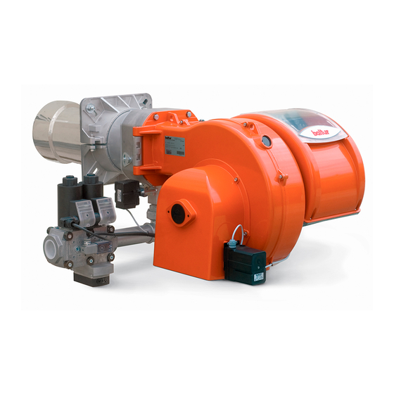
ITALIANO DESCRIZIONE COMPONENTI Testa di combustione Guarnizione Flangia attacco bruciatore Servomotore regolazione aria Sinottico Quadro elettrico Gruppo serrande aria Cerniera Motore ventola Convogliatore aria in aspirazione Presa di pressione gas alla testa di combustione Servomotore regolazione gas Dispositivo regolazione testa Targa identifi cazione bruciatore QUADRO ELETTRICO TBG 450 - 510LX ME... -
Page 12: Descrizione Componenti
ITALIANO DESCRIZIONE COMPONENTI Testa di combustione Guarnizione Flangia attacco bruciatore Servomotore regolazione aria Sinottico Quadro elettrico Gruppo serrande aria Cerniera Motore ventola Convogliatore aria in aspirazione Presa di pressione gas alla testa di combustione Servomotore regolazione gas Dispositivo regolazione testa Targa identifi cazione bruciatore QUADRO ELETTRICO TBG 650 - 750LX ME... -
Page 13: Dimensioni Di Ingombro
ITALIANO DIMENSIONI DI INGOMBRO Modello TBG 450LX ME 1060 1850 TBG 510LX ME 1060 1850 TBG 650LX ME 1110 1850 TBG 750LX ME 1180 1850 Modello E Ø F Ø LØ N Ø TBG 450LX ME 547 ÷ 597 DN80 520 ÷... -
Page 14: Caratteristiche Costruttive
ITALIANO CARATTERISTICHE COSTRUTTIVE CARATTERISTICHE TECNICO FUNZIONALI Il bruciatore risulta composto da: • Bruciatore di gas conforme alle normative europee EN 676 ed alle • Parte ventilante in lega leggera d'alluminio. Direttive Europee 2006/42/CE; 2014/30/UE; 2014/35/UE; (UE) • Ventilatore centrifugo per alte prestazioni. 2016/426. -
Page 15: Applicazione Del Bruciatore Alla Caldaia
ITALIANO APPLICAZIONE DEL BRUCIATORE ALLA CALDAIA MONTAGGIO GRUPPO TESTA La testa di combustione viene imballata separatamente dal corpo ventilante. Fissare il gruppo testa al portellone caldaia nel seguente modo: • Posizionare sul canotto la guarnizione isolante (13). • Fissare la fl angia del gruppo testa (19) alla caldaia (1) tramite i prigionieri, le rondelle e i relativi dadi in dotazione (7). - Page 16 ITALIANO MONTAGGIO CORPO VENTILANTE • Il bruciatore è predisposto di cerniera ad apertura ambidestra per un comodo accesso alla testa di combustione con bruciatore mon- tato. Dopo aver installato il gruppo testa sulla caldaia, posizionare il corpo ventilante (2) e le relative rondelle (5) in corrispondenza delle cerniere (22).
- Page 17 Sono possibili diverse soluzioni di montaggio 8, 8a 9 9a della rampa gas. A CURA DELL’INSTALLATORE 0002910902 LIMITE DI FORNITURA BALTUR Servomotore regolazione aria Valvola di sicurezza Pressostato aria Pressostato gas di minima e controllo fughe gas...
-
Page 18: Collegamenti Elettrici
ITALIANO COLLEGAMENTI ELETTRICI • Tutti i collegamenti devono essere eseguiti con fi lo elettrico fl essi- bile. • Le linee elettriche devono essere distanziate dalle parti calde. • L’installazione del bruciatore è consentita solo in ambienti con gra- do di inquinamento 2 come indicato nell’allegato M della norma EN 60335-1:2008-07. - Page 19 ITALIANO • Installare un idoneo sezionatore di manovra per ciascuna linea di alimentazione del bruciatore seguendo le indicazioni riportate nello schema a fi anco e in tabella 1. fig1 PROTEZIONE CON SEZIONATORE, MAGNETOTERMICO E INTERRUTTORE DIFFERENZIALE TABELLA 1 TBG 450 ME TBG 510 ME TBG 650 ME TBG 750 ME...
- Page 20 ITALIANO • Installare un idoneo sezionatore di manovra e i fusibili di protezione per ciascuna linea di alimentazione del bruciatore seguendo le indi- cazioni riportate nello schema a fi anco e in tabella 2. fig2 PROTEZIONE CON SEZIONATORE E FUSIBILI TABELLA 2 TBG 450 ME TBG 510 ME...
- Page 21 ITALIANO ESEMPIO 1: Si riporta, ad esclusivo titolo di esempio, il calcolo della massima im- pedenza dell’anello di guasto ammessa in un sistema "TN", defi nita la CALCOLO DELLA MASSIMA IMPEDENZA DELL’ANELLO DI taglia, la marca e il modello del fusibile di protezione. GUASTO Utilizzare la documentazione che riporta le curve di intervento relative alla marca e al modello del fusibile utilizzato per la protezione, avente...
- Page 22 ITALIANO ESEMPIO 2: Si riporta, ad esclusivo titolo di esempio, il calcolo della massima im- pedenza dell’anello di guasto ammessa in un sistema "TT", defi nita la CALCOLO DELLA MASSIMA IMPEDENZA DELL’ANELLO DI taglia, la marca e il modello del fusibile di protezione. GUASTO Utilizzare la documentazione che riporta le curve di intervento relative alla marca e al modello del fusibile utilizzato per la protezione, avente...
-
Page 23: Descrizione Del Funzionamento
ITALIANO DESCRIZIONE DEL FUNZIONAMENTO Se anche con erogazione al minimo si raggiunge il valore limite di temperatura o pressione a cui è regolato il dispositivo di controllo, il I bruciatori ad aria soffi ata con modulazione elettronica sono adatti bruciatore viene arrestato. per funzionare su focolari in forte pressione o in depressione secondo Riabbassandosi, la temperatura o pressione al di sotto del valore di le relative curve di lavoro. -
Page 24: Descrizione Del Funzionamento Della Modulazione
ITALIANO DESCRIZIONE DEL FUNZIONAMENTO DELLA MODULAZIONE Quando il bruciatore è acceso alla portata minima, se la sonda di modulazione lo consente (regolata ad un valore di temperatura o pressione superiore a quella esistente in caldaia) il servomotore di regolazione aria / gas inizia a girare; •... -
Page 25: Accensione E Regolazione
ITALIANO ACCENSIONE E REGOLAZIONE questo modo la modulazione è inserita esclusivamente con il co- mando automatico della sonda di caldaia. • Verifi care che la tensione della linea elettrica corrisponda a quella • Verifi care l'effi cienza dei termostati o pressostati di caldaia (l'inter- richiesta dal costruttore e, che tutti i collegamenti elettrici realizzati vento deve arrestare il bruciatore). -
Page 26: Sensore Fiamma
ITALIANO Qualora il pressostato aria non rilevi una pressione superiore a quella arrestarsi in “blocco”.Effettuare questa verifi ca anche con brucia- di taratura, l'apparecchiatura esegue il suo ciclo ma non si inserisce tore già acceso. Scollegando il cavo dell'elettrodo di ionizzazione, il trasformatore d'accensione e non si aprono le valvole del gas e di l’apparecchiatura si deve portare immediatamente in “blocco”. -
Page 27: Schema Di Regolazione Testa Di Combustione E Distanza Disco Elettrodi
ITALIANO SCHEMA DI REGOLAZIONE TESTA DI COMBUSTIONE E DISTANZA DISCO ELETTRODI 1 - Elettrodo ionizzazione Modello 2 - Elettrodo accensione TBG 450 3 - Disco fi amma TBG 510 TBG 650 4 - Miscelatore TBG 750 Posizione (z) Entrata gas Default Flangia attacco bruciatore Pomello regolazione testa di combustione. -
Page 28: Manutenzione
ITALIANO MANUTENZIONE Effettuare almeno una volta all’anno e comunque in conformità alle norme vigenti, l’analisi dei gas di scarico della combustione verifi can- do la correttezza dei valori di emissioni. • Pulire le serrande aria, il pressostato aria con presa di pressione ed il relativo tubo se presenti. -
Page 29: Tempi Di Manutenzione
ITALIANO TEMPI DI MANUTENZIONE Descrizione particolare Azione da eseguire TESTA DI COMBUSTIONE CONTROLLO VISIVO, INTEGRITA' CERAMICHE, SMERIGLIATURA ESTREMITA', VERIFICARE ELETTRODI ANNUO DISTANZA, VERIFICARE CONNESSIONE ELETTRICA DISCO FIAMMA CONTROLLO VISIVO INTEGRITA' EVENTUALI DEFORMAZIONI, PULIZIA ANNUO CONTROLLO VISIVO, INTEGRITA' CERAMICHE, SMERIGLIATURA ESTREMITA', VERIFICARE SONDA DI IONIZZAZIONE ANNUO DISTANZA, VERIFICARE CONNESSIONE ELETTRICA... -
Page 30: Vita Attesa
ITALIANO VITA ATTESA La vita attesa dei bruciatori e dei relativi componenti dipende molto dal tipo di applicazione su cui il bruciatore è installato, dai cicli, dalla potenza erogata, dalle condizioni dell’ambiente in cui si trova, dalla frequenza e modalità di manutenzione, ecc. ecc. Le normative relative ai componenti di sicurezza prevedono una vita attesa di progetto espressa in cicli e/o anni di funzionamento. -
Page 31: Precisazioni Sull'uso Del Propano
ITALIANO PRECISAZIONI SULL'USO DEL PROPANO PERICOLO / ATTENZIONE La potenza massima e minima (kW) del bruciatore, è consi- • Valutazione, indicativa, del costo di esercizio; derata con combustibile metano che coincide approssimativa- - 1 m3 di gas liquido in fase gassosa ha un potere calorifi co mente con quella del propano. -
Page 32: Schema Di Principio Per Riduzione Pressione G.p.l. A Due Stadi Per Bruciatore Oppure Caldaia
ITALIANO SCHEMA DI PRINCIPIO PER RIDUZIONE PRESSIONE G.P.L. A DUE STADI PER BRUCIATORE OPPURE CALDAIA Manometro e presa di pressione Riduttore di 1° salto Riduttore di 2° salto Uscita ~ 1,5 bar Uscita ~ 30 hPa (mbar) Portata ~ il doppio del massimo richiesto dall’utilizzatore Portata ~ il doppio del massimo richiesto dall’utilizzatore Giunto antivibrante Filtro... -
Page 33: Istruzioni Per L'accertamento Delle Cause Di Irregolarità Nel Funzionamento E La Loro Eliminazione
ITALIANO ISTRUZIONI PER L'ACCERTAMENTO DELLE CAUSE DI IRREGOLARITÀ NEL FUNZIONAMENTO E LA LORO ELIMINAZIONE IRREGOLARITÁ POSSIBILE CAUSA RIMEDIO 1 Invertire l'alimentazione (lato 230V) del trasformatore di accensione e verifi care con 1 Disturbo della corrente di ionizzazione da micro-amperometro analogico. parte del trasformatore di accensione. -
Page 34: Schemi Elettrici
ITALIANO SCHEMI ELETTRICI 32 / 44 0006160281_202007... - Page 35 ITALIANO 33 / 44 0006160281_202007...
- Page 36 ITALIANO 34 / 44 0006160281_202007...
- Page 37 ITALIANO 35 / 44 0006160281_202007...
- Page 38 ITALIANO 36 / 44 0006160281_202007...
- Page 39 ITALIANO 37 / 44 0006160281_202007...
- Page 40 ITALIANO 38 / 44 0006160281_202007...
- Page 41 ITALIANO 39 / 44 0006160281_202007...
- Page 42 ITALIANO 40 / 44 0006160281_202007...
- Page 43 ITALIANO 41 / 44 0006160281_202007...
- Page 44 ITALIANO 42 / 44 0006160281_202007...
- Page 45 ITALIANO 43 / 44 0006160281_202007...
- Page 46 ITALIANO APPARECCHIATURA Corrente ionizzazione minima 1,4 µA ** Solo per taratura SENSORE FIAMMA SONDA DI TEMPERATURA ACQUA CAUTELA / AVVERTENZE SONDA DI TEMPERATURA ESTERNA Per il dimensionamento delle sezioni S1, S2 e il dimensiona- mento dei dispositivi di protezione Q1, Q2, SG1, SG2, FV1, FV2 SONDA DI TEMPERATURA GAS DI SCARICO fare riferimento al capitolo "COLLEGAMENTI ELETTRICI".
- Page 47 ENGLISH ENGLISH SUMMARY Warnings for use in safety conditions ..................................2 Standard accessories .......................................7 Burner identifi cation plate ....................................7 Data recorded during fi rst start-up ..................................7 Operating range .......................................8 Component description ....................................9 Electrical panel .........................................9 Component description ....................................10 Electrical panel .......................................10 Overall dimensions ......................................
-
Page 48: Warnings For Use In Safety Conditions
ENGLISH WARNINGS FOR USE IN SAFETY • Children must be watched over to prevent them from playing with the equipment. CONDITIONS • This appliance should only be used for the purpose it has been de- signed for. Any other use is to be considered improper and therefore PURPOSE OF THIS MANUAL dangerous. - Page 49 Contact only qualifi ed personnel. locking devices of mechanical securing systems are properly • Any product repairs must only be carried out by BALTUR authorised tightened. assistance centres or by its local distributor using only original spare - Make sure that the use and maintenance manual of the burner is parts.
- Page 50 ENGLISH SPECIAL PRECAUTIONS WHEN USING GAS. - in case of rubber sheath, at least type H05RR-F; LiYCY • Check that the feed line and the train comply with current law and 450/750V regulations. - without any sheath, at least type FG7 o FROR, FG70H2R •...
- Page 51 ENGLISH • For protection devices, refer to the tables 1, 2, in the chapter ELECTRICAL CONNECTIONS. • Do not reduce the section of the conductors indicated in table 1 and 2. A maximum short-circuit current of 10kA is required at the connection point (before protection devices) in order to ensure the correct intervention of protection devices, see the chapter ELECTRI- CAL CONNECTIONS.
- Page 52 ENGLISH MODEL TBG 450LX ME TBG 510LX ME TBG 650LX ME TBG 750LX ME Maximum natural gas heat power 4800 5100 6500 7500 Minimum natural gas heat power mg/kWh ¹) natural gas emissions Class 3 Class 3 Class 3 Class 3...
- Page 53 ENGLISH STANDARD ACCESSORIES MODEL TBG 450LX ME TBG 510LX ME TBG 650LX ME TBG 750LX ME Burner coupling fl ange gasket Stud bolts N°4 M20 N°4 M20 N°4 M20 N°4 M20 Hexagon nuts No.4 M20 - No.4 M12 No.4 M20 - No.4 M12 No.4 M20 - No.4 M12...
- Page 54 ENGLISH ¹) NATURAL GAS EMISSIONS ²) PROPANE GAS EMISSIONS Classes defi ned according to EN 676 standards. Classes defi ned according to EN 676 standards. NOx emissions in mg/kWh natural NOx emissions in mg/kWh propane Class Class ≤ 170 ≤ 230 ≤...
-
Page 55: Burner Identifi Cation Plate
ENGLISH COMPONENT DESCRIPTION Combustion head Seal Burner connection fl ange Air regulation servomotor Synoptic control panel Electrical panel Air gate unit Hinge Fan motor Intake air conveyor Gas pressure port to combustion head Gas regulation servomotor Combustion head adjustment device Burner identifi cation plate ELECTRICAL PANEL TBG 450 - 510LX ME... -
Page 56: Electrical Panel
ENGLISH COMPONENT DESCRIPTION Combustion head Seal Burner connection fl ange Air regulation servomotor Synoptic control panel Electrical panel Air gate unit Hinge Fan motor Intake air conveyor Gas pressure port to combustion head Gas regulation servomotor Combustion head adjustment device Burner identifi cation plate ELECTRICAL PANEL TBG 650 - 750LX ME... -
Page 57: Overall Dimensions
ENGLISH OVERALL DIMENSIONS Model TBG 450LX ME 1060 1850 TBG 510LX ME 1060 1850 TBG 650LX ME 1110 1850 TBG 750LX ME 1180 1850 Model E Ø F Ø LØ N Ø TBG 450LX ME 547 ÷ 597 DN80 520 ÷ 600 TBG 510LX ME 547 ÷... -
Page 58: Design Characteristics
ENGLISH DESIGN CHARACTERISTICS TECHNICAL FUNCTIONAL CHARACTERISTICS The burner consists of: • Gas burner compliant with the European standards EN 676 and • Ventilating part in light aluminium alloy. with the European Directives 2006/42/CE; 2014/30/UE; 2014/35/ • Centrifugal fan for high performances. UE;... -
Page 59: Burner Connection To The Boiler
ENGLISH BURNER CONNECTION TO THE BOILER HEAD UNIT ASSEMBLY The combustion head is packaged separately from the body of the burner. Anchor the head unit to the boiler door as follows: • Position the insulating seal on the sleeve (13). •... - Page 60 ENGLISH ASSEMBLY OF VENTILATION SYSTEM • The burner has an ambidextrous hinge opening for easy access to the combustion head with fi tted burner. After having installed the head unit on boiler, position the ventilating body (2) and relevant washers (5) close to hinges (22). •...
- Page 61 The gas train can be assembled 8, 8a 9 9a in different ways. TO BE CARRIED OUT BY THE INSTALLER 0002910902 BALTUR SUPPLY LIMIT Air regulation servomotor Safety valve Air pressure switch Minimum gas pressure switch and gas leak control...
-
Page 62: Electrical Connections
ENGLISH ELECTRICAL CONNECTIONS • It is advisable to make all connections with fl exible electric wire. • The power lines must be distanced from the hot parts. • The burner installation is allowed only in environments with pollu- tion degree 2 as indicated in annex M of the EN 60335-1:2008-07 regulation. - Page 63 ENGLISH • Install a suitable disconnecting switch for each power supply line of the burner, following the indications in the diagram on the side and in the table 1. fig1 PROTECTION WITH DISCONNECTING SWITCH, CIRCUIT BREAKER AND DIFFERENTIAL SWITCH TABLE 1 TBG 450 ME TBG 510 ME TBG 650 ME...
- Page 64 ENGLISH • Install a suitable disconnecting switch and protection fuses for each power supply line of the burner, following the indications in the dia- gram on the side and in the table 2. fig2 PROTECTION WITH DISCONNECTING SWITCH AND FUSES TABLE 2 TBG 450 ME TBG 510 ME...
- Page 65 ENGLISH EXAMPLE NO. 1: Only by way of example, fi nd below the calculation of the maximum fault loop impedance allowed in a "TN" system, with the defi nition of CALCULATION OF THE MAXIMUM FAULT LOOP IMPEDANCE the protection fuse size, brand and model. Use the documentation showing the intervention curves related to the System brand and the model of the fuse used for the protection, having the size...
- Page 66 ENGLISH EXAMPLE NO. 2: Only by way of example, fi nd below the calculation of the maximum fault loop impedance allowed in a "TT" system, with the defi nition of CALCULATION OF THE MAXIMUM FAULT LOOP IMPEDANCE the protection fuse size, brand and model. Use the documentation showing the intervention curves related to the System brand and the model of the fuse used for the protection, having the size...
-
Page 67: Operating Description
ENGLISH OPERATING DESCRIPTION measures any variation in temperature or pressure and automatical- ly adjusts the fuel and combustion air fl ow rate through the relevant Blown air burners with electronic modulation may be used on hearths servomotors. under strong pressure or in a vacuum, according to the corresponding •... -
Page 68: Modulation Operation Description
ENGLISH MODULATION OPERATION DESCRIPTION When the burner is ignited at the minimum fl ow-rate, if the modula- tion probe allows it (adjusted to a temperature or pressure which is greater than that present in the boiler) the air adjustment servomotor begins to operate, •... -
Page 69: Starting Up And Regulation
ENGLISH STARTING UP AND REGULATION The air pressure switch stops the equipment operation if air pressure is not at the expected value. • Make sure that the mains voltage corresponds to the manufactu- The pressure switch must therefore be adjusted so that it is triggered rer's requirements and that all electrical connections made at the to close the NO (normally open) contact when the air pressure in the installation site are effected properly as illustrated in our wiring dia-... -
Page 70: Flame Sensor
ENGLISH If the air pressure switch does not detect a pressure greater than that ionisation electrode lead, the equipment must immediately go into calibrated, the equipment runs through its cycle but does not switch its “lock-out” action. on the ignition transformer and does not open the gas valves and so When fi rst switching on the burner it is essential to check that they the burner “locks-out”. -
Page 71: Diagram For Regulating The Combustion Head And The Electrode Disk Distance
ENGLISH DIAGRAM FOR REGULATING THE COMBUSTION HEAD AND THE ELECTRODE DISK DISTANCE 1 - Ionisation electrode Model 2 - Ignition electrode TBG 450 3 - Flame disc TBG 510 TBG 650 4 - Mixer TBG 750 Position (z) Gas inlet Default Burner connection fl... -
Page 72: Maintenance
ENGLISH MAINTENANCE Analyse combustion gases and check that the emission values are correct at least once a year, in compliance with current law. • Clean air dampers, the air pressure switch with pressure port and the relevant pipe, if any. •... -
Page 73: Maintenance Time
ENGLISH MAINTENANCE TIME Part description Action to be performed COMBUSTION HEAD VISUAL INSPECTION OF THE INTEGRITY OF CERAMICS. TIP GRINDING, CHECK DISTANCE, ELECTRODES YEARLY CHECK ELECTRICAL CONNECTION FLAME DISC INTEGRITY VISUAL CHECK FOR ANY DEFORMATIONS, CLEANING, YEARLY VISUAL INSPECTION OF THE INTEGRITY OF CERAMICS. TIP GRINDING, CHECK DISTANCE, IONISATION PROBE YEARLY CHECK ELECTRICAL CONNECTION... -
Page 74: Expected Lifespan
ENGLISH EXPECTED LIFESPAN The expected lifespan of burners and relevant components depends very much from the type of application on which the burner is installed, from cycles ,of delivered power, from the conditions of the environment in which it is located, from maintenance frequency and mode, etc. Standards about safety components provide for a project expected lifespan expressed in cycles and/or years of operation. -
Page 75: Specifications For Propane Use
ENGLISH SPECIFICATIONS FOR PROPANE USE DANGER / ATTENTION The maximum and minimum power (kW) of the burner refers • Operating costs approximate assessment; to natural gas which is more or less the same as with propane. - 1 m3 of liquid gas in gaseous stage has a lower heating capaci- •... -
Page 76: Block Diagram Illustrating The Principle Of L.p.g. Pressure Reduction In Two Stages For Burner Or Boiler
ENGLISH BLOCK DIAGRAM ILLUSTRATING THE PRINCIPLE OF L.P.G. PRESSURE REDUCTION IN TWO STAGES FOR BURNER OR BOILER Pressure gauge and pressure intake 1st step reducer 2nd step reducer Output ~ 1.5 bar Output ~ 30 hPa (mbar) Flow rate ~ double the maximum required by the user Flow rate ~ double the maximum required by the user Vibration-proof joint Filter... -
Page 77: Instructions For Determining The Cause Leading To Irregularities In The Operation And Their Elimination
ENGLISH INSTRUCTIONS FOR DETERMINING THE CAUSE LEADING TO IRREGULARITIES IN THE OPERATION AND THEIR ELIMINATION IRREGULARITY POSSIBLE CAUSE REMEDY 1 Invert the ignition transformer power supply (230V side) and check using an analogue 1 Disturbance to ionization current from the micro-ammeter. -
Page 78: Wiring Diagrams
ENGLISH WIRING DIAGRAMS 32 / 44 0006160281_202007... - Page 79 ENGLISH 33 / 44 0006160281_202007...
- Page 80 ENGLISH 34 / 44 0006160281_202007...
- Page 81 ENGLISH 35 / 44 0006160281_202007...
- Page 82 ENGLISH 36 / 44 0006160281_202007...
- Page 83 ENGLISH 37 / 44 0006160281_202007...
- Page 84 ENGLISH 38 / 44 0006160281_202007...
- Page 85 ENGLISH 39 / 44 0006160281_202007...
- Page 86 ENGLISH 40 / 44 0006160281_202007...
- Page 87 ENGLISH 41 / 44 0006160281_202007...
- Page 88 ENGLISH 42 / 44 0006160281_202007...
- Page 89 ENGLISH 43 / 44 0006160281_202007...
- Page 90 ENGLISH CONTROL BOX Minimum ionisation current 1.4 μA ** For calibration only Flame sensor WATER TEMPERATURE PROBE CAUTION / WARNINGS EXTERNAL TEMPERATURE PROBE For the dimensioning of sections S1, S2 and the dimensioning of protection devices Q1, Q2, SG1, SG2, FV1, FV2 refer to the EXHAUST GAS TEMPERATURE PROBE chapter “ELECTRICAL CONNECTIONS”.
- Page 92 BALTUR S.P.A. Via Ferrarese, 10 44042 Cento (Fe) - Italy Tel. +39 051-6843711 Fax. +39 051-6857527/28 www.baltur.it info@baltur.it Il presente catalogo riveste carattere puramente indicativo. La casa, pertanto, si riserva ogni possibilità di modifica dei dati tecnici e di quant'altro in esso riportato.
Need help?
Do you have a question about the TBG 450LX ME and is the answer not in the manual?
Questions and answers