Table of Contents
Advertisement
Quick Links
Advertisement
Table of Contents

Related Manuals for PerkinElmer Frontier Optica FT-IR


Summary of Contents for PerkinElmer Frontier Optica FT-IR
- Page 1 MOLECULAR SPECTROSCOPY FT-IR RONTIER PTICA User’s Guide...
- Page 2 The information contained in this document is subject to change without notice. Except as specifically set forth in its terms and conditions of sale, PerkinElmer makes no warranty of any kind with regard to this document, including, but not limited to, the implied warranties of merchantability and fitness for a particular purpose.
-
Page 3: Table Of Contents
Warning Signs on the Instrument ..............21 EMC Compliance ....................22 EC Directive ....................22 FCC rules and regulations................22 An Overview of the Frontier Optica FT-IR Spectrometer ......23 A Guided Tour of the Frontier Optica FT-IR Spectrometer ........24 Optical system ...................25 Top panel controls ..................26 The sample compartment ................26... - Page 4 Appendix 1: Changing the Sampling Accessory ..........86 Appendix 2: Instrument Self-Checks ..............88 Appendix 3: Instrument Performance Validation Kit ........... 90 Appendix 4: Decontamination and Cleaning ............91 Appendix 5: WEEE Instructions for PerkinElmer Products ........92 Index ......................93...
-
Page 5: Introduction
Introduction... -
Page 6: About This Manual
6 . Frontier Optica FT-IR User's Guide About This Manual This manual contains the following sections: • Introduction • Warnings and Safety Information • An Overview of the Frontier Optica FT-IR Spectrometer Unpacking and Installation • Using the Spectrometer • Measuring Optical Components • •... -
Page 7: Conventions Used In This Manual
ALT+F. All eight digit numbers are PerkinElmer part numbers unless stated otherwise. The term “instrument” refers to the Frontier Optica FT-IR spectrometer, and any sampling accessory fitted. - Page 8 8 . Frontier Optica FT-IR User's Guide We use the term CAUTION to inform you about situations that could result in serious damage to the instrument or other equipment. Details CAUTION about these circumstances are in a box like this one.
- Page 9 Introduction . 9 We use the term WARNING to inform you about situations that could result in personal injury to yourself or other persons. Details about these circumstances are in a box like this one. WARNING Warning (Warnung) Bedeutet, daß es bei Nichtbeachten der genannten Anweisung zu einer Verletzung des Benutzers kommen kann.
- Page 10 10 . Frontier Optica FT-IR User's Guide...
-
Page 11: Warnings And Safety Information
Warnings and Safety Information... -
Page 12: Safety Summary
12 . Frontier Optica FT-IR User's Guide Safety Summary The Frontier Optica FT-IR spectrometer has been designed to comply with a wide variety of international standards governing the safety of laboratory equipment. In routine use, the instruments pose virtually no risk to you. If you take some simple, common-sense... -
Page 13: General Safety
Warnings and Safety Information . 13 General Safety The Frontier Optica FT-IR spectrometer has been designed and tested in accordance with PerkinElmer specifications and in accordance with the safety requirements of the International Electrotechnical Commission (IEC). The instruments conform to IEC publication 61010-1 (“Safety requirements for electrical equipment for measurement, control, and... -
Page 14: Location And Ventilation
14 . Frontier Optica FT-IR User's Guide Location and Ventilation Make sure that the switch at the electrical supply inlet on the rear of the instrument is not obstructed. WARNING To allow for adequate cooling Do not site the instrument near to room heating equipment, for example, central heating radiators. -
Page 15: Use Of Flammable Solvents And Samples
Warnings and Safety Information . 15 Use of flammable solvents and samples The instrument contains a hot source and contact with flammable vapors may cause an explosion. When working with flammable solvents or samples, particularly during unattended operation with flow-cells, it is recommended that the instrument optics area should be continuously WARNING purged with dry air or nitrogen to maintain a positive pressure and... -
Page 16: Electrical Safety
16 . Frontier Optica FT-IR User's Guide Electrical Safety Connect the instrument to a power supply line that includes a switch or other means of • disconnection from the electricity supply. • Only plug the instrument into an electricity-supply socket that is provided with a protective earth connection. -
Page 17: Laser Safety Regulations
Warnings and Safety Information . 17 Laser Safety Regulations The Frontier Optica FT-IR spectrometer is a Class 1 laser product as defined by IEC 60825-1. The optical module contains a Class 2 Helium Neon (HeNe) laser, which emits visible, continuous wave radiation at a wavelength of 633 nm and has a maximum output power of 1 mW. -
Page 18: Laser Radiation Hazards And Their Classification
18 . Frontier Optica FT-IR User's Guide Laser Radiation Hazards and their Classification Indirect observation of the laser beam radiation in the optical path is not hazardous. Directly viewing the laser beam along its axis (allowing the laser beam radiation to pass into the eye) can be hazardous, depending upon the power of the beam, the length of time that the eye is exposed to the beam and the optical efficiency of the exposed eye. -
Page 19: Labels
The product identification label is on the front of the instrument. Other labels are fixed to the Frontier Optica FT-IR spectrometer in the locations shown in Figure 1 and Figure 2: Figure 1 Labels (rear of instrument) - Page 20 20 . Frontier Optica FT-IR User's Guide Serial number, part number and date of manufacture NOTE: There is a second copy of the CAUTION label inside the sample compartment cover. Figure 2 Labels (sample compartment)
-
Page 21: Warning Signs On The Instrument
Warnings and Safety Information . 21 Warning Signs on the Instrument Caution, hot surface. Caution, risk of electric shock. Caution, laser radiation hazard. Caution, risk of danger. Refer to accompanying documents in all cases where this symbol is used to find out the nature of the potential hazard and any actions which have to be taken. -
Page 22: Emc Compliance
EMC Compliance EC Directive The Frontier Optica FT-IR spectrometer has been designed and tested to meet the requirements of the EC Directive 2004/108/EC. The instrument complies with the EMC standard EN 61326-1 (EMC standard for electrical equipment for measurement, control and laboratory use). -
Page 23: An Overview Of The Frontier Optica Ft-Ir Spectrometer
An Overview of the Frontier Optica FT-IR Spectrometer... -
Page 24: A Guided Tour Of The Frontier Optica Ft-Ir Spectrometer
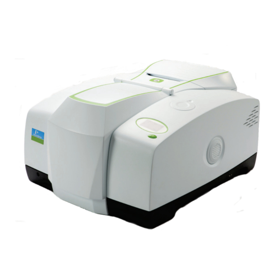
24 . Frontier Optica FT-IR User's Guide A Guided Tour of the Frontier Optica FT-IR Spectrometer The PerkinElmer Frontier Optica FT-IR spectrometer (Figure 3) is a bench-top instrument that has been designed to provide high ordinate accuracy for measurements on optical components. -
Page 25: Optical System
(an internal humidity sensor is available as an option). In the Frontier Optica FT-IR spectrometer, KBr windows separate the sample compartment from the purged optical system. You can purge the sample compartment with clean, dry, oil-free air or nitrogen. -
Page 26: Top Panel Controls
26 . Frontier Optica FT-IR User's Guide Top panel controls Display Go button Figure 4 Top panel controls The display on the front right of the top of your instrument has two purposes: • To display messages generated by the instrument’s firmware, such as those that monitor initialization and diagnostics when the instrument is switched on. -
Page 27: Accessories For The Frontier Optica Ft-Ir Spectrometer
An Overview of the Frontier Optica FT-IR Spectrometer . 27 The Frontier Optica FT-IR spectrometer is fitted with sample compartment windows that are composed of KBr that, although coated, can be CAUTION damaged by high levels of humidity. If you spill a liquid in the sample compartment, wipe it up quickly. When working with water-based samples open to the air, either purge the sample compartment or leave the cover open. -
Page 28: Storage Compartment
28 . Frontier Optica FT-IR User's Guide Storage compartment You can store your polystyrene reference film, sample slides and other small accessories in the storage compartment on the top of the spectrometer (Figure 7). Figure 7 Storage compartment on top of the spectrometer... -
Page 29: Unpacking And Installation
Unpacking and Installation... -
Page 30: Requirements
They contain important information. Electrical requirements The Frontier Optica FT-IR spectrometer can operate on electricity supplies of 50 or 60 Hz and in the 100 V to 230 V range without any adjustment. The nominal power consumption of the instrument is 120 VA. - Page 31 Unpacking and Installation . 31 The instrument has been designed for indoor use and operates correctly under the following conditions: Ambient temperature 15 °C to 35 °C Ambient relative humidity 80% maximum (non-condensing).
-
Page 32: Unpacking The Spectrometer
2 A, 250 V time lag fuse L9003693 8.0 mm hexagonal wrench L1050002 IR & Raman Manuals CD L1250450 Germanium test sample kit LX108873 Spectrum Standard Software Kit L1250230 Spectrum Configuration Disk If any items are missing or damaged, contact your local PerkinElmer office. - Page 33 Unpacking and Installation . 33 2. Carefully remove the instrument from the shipping container, but not from the bag in which it was shipped. The spectrometer must be allowed to reach the temperature of its surroundings before it is removed from the bag. This means leaving it CAUTION overnight if it has been moved from a cold area, and at least 4 hours after removal from the shipping container.
-
Page 34: The Desiccant Indicator
34 . Frontier Optica FT-IR User's Guide The Desiccant Indicator The optical system of the spectrometer is purged at the factory. This protects the beamsplitter and the sample compartment windows from being damaged by humidity. Replaceable packs of desiccant keep the optics dry and free of CO The top panel of the instrument includes a desiccant indicator, whose sectors change sequentially from blue to pink as the desiccant packs are exhausted (Figure 8). -
Page 35: Connecting Up The Spectrometer
Unpacking and Installation . 35 Connecting up the Spectrometer Connecting to the PC NOTE: To control your instrument from a PC, use the crossover cable supplied. To control your instrument over your network, use a standard Ethernet cable (not supplied). 1. -
Page 36: Other Connectors
36 . Frontier Optica FT-IR User's Guide Other connectors The communication ports for peripheral devices are shown in Figure 10. Instrument purge 10101 Spt. Lt. Sample area purge EXT.R Figure 10 Communication ports Icons that identify the function of each of the Communication ports are printed on the hinge molding directly above the port. -
Page 37: Connecting The Spectrometer To The Electrical Supply
+5 V Microscope external detector 15-way +12 V 0.65 A module. Connects to a high density PerkinElmer infrared microscope, D-type −12 V 0.65 A placed on the left of the instrument. +5 V Connecting the spectrometer to the electrical supply The power cable for the electrical supply plugs into the rear of the instrument. - Page 38 38 . Frontier Optica FT-IR User's Guide The Frontier Optica FT-IR spectrometer can operate on electricity supplies of 50 Hz or 60 Hz and in the 100 V to 230 V range without any adjustment. 1. Fit the molded socket of the power cable into the electrical supply inlet (Figure 11) of the instrument.
-
Page 39: Installing The Instrument In The Software
Unpacking and Installation . 39 Installing the Instrument in the Software Before you can use the instrument it must be set up in the software. Installing the software NOTE: If you are supplying your own computer, make sure that it meets the minimum requirements for hardware and software set out in the “PC Requirements”... - Page 40 40 . Frontier Optica FT-IR User's Guide...
-
Page 41: Using The Spectrometer
Using the Spectrometer... -
Page 42: Basics Of Software Control
To save time, we suggest that you leave the instrument switched on at all times. 2. From the Start menu select Programs; the PerkinElmer Applications group; the Spectrum sub-group and then the Spectrum application. Double-click the shortcut icon on the desktop. -
Page 43: Scanning Samples
Using the Spectrometer . 43 Scanning samples When you connect to your spectrometer the instrument settings will default to appropriate values for your instrument type and accessory. The configurable Scan toolbars at the top of the workspace include the tools you need to collect a sample spectrum. -
Page 44: Working With The Instrument Display And Go Button
44 . Frontier Optica FT-IR User's Guide 3. Place your sample in the instrument and then click to begin scanning your sample. By default, during scanning the sample data is displayed on the Live tab in the Viewing Area. The completed spectrum is displayed on the Graph tab, and added to the current Samples View in the Data Explorer. -
Page 45: Atmospheric (Co O) Suppression
Using the Spectrometer . 45 Atmospheric (CO O) Suppression Atmospheric suppression can be selected in the Setup Instrument Advanced tab (Figure 14). Figure 14 Setup Instrument Advanced tab in Spectrum What is atmospheric suppression? This is an atmospheric correction routine. This routine is more powerful than simple subtraction, overcoming the following issues: •... - Page 46 46 . Frontier Optica FT-IR User's Guide Figure 16 Atmospheric suppression NOTE: Atmospheric suppression should be used with caution when measuring optical –1 components. For example, when measuring a 1600 cm passband filter suppressing the CO absorption may produce errors in that region of the spectrum.
-
Page 47: Avi Correction
Using the Spectrometer . 47 AVI Correction AVI correction can be selected in the Setup Instrument Advanced tab in Spectrum (Figure 14). AVI correction can only be performed if an AVI Calibration has been set up for the current configuration and resolution. Select AVI from the Adjustments Toolbox, available from the Setup Instrument Advanced Tab. -
Page 48: Look Ahead
48 . Frontier Optica FT-IR User's Guide Look Ahead Look Ahead can be selected in the Setup Instrument Advanced tab (Figure 14). What is Look Ahead? Look Ahead is a novel system where the spectrometer scans continuously and uses the properties of the measured spectrum to identify changes corresponding to sample removal, sample insertion, or sample change, automatically. -
Page 49: Quality Checks
Using the Spectrometer . 49 Quality Checks Quality Checks can be selected in the Setup Instrument Advanced tab (Figure 14). What are Quality Checks? Quality checking is a tool for less experienced IR users that identifies possible problems in the spectrum being collected and suggests ways of improving the measurement. What do Quality Checks do? Simply select the Quality Checks that you want to perform from the list in the Setup Instrument Advanced tab and, if required, adjust the threshold range using the slider bars. - Page 50 50 . Frontier Optica FT-IR User's Guide...
-
Page 51: Measuring Optical Components
Measuring Optical Components... -
Page 52: Optimizing Your Instrument Settings
52 . Frontier Optica FT-IR User's Guide Optimizing Your Instrument Settings The Frontier Optica FT-IR instrument has been designed to have high ordinate accuracy for use in applications such as optical component measurements. This section contains some guidelines to help you to get the best performance out of your instrument. -
Page 53: B-Stop
FT-IR measurements in wavenumbers (cm ) have constant resolution over the entire range. If wavenumbers are converted to wavelength (for the Frontier Optica FT-IR, measured in microns or nanometers) the resolution varies as a function of wavelength. The relationship between wavenumber resolution, wavenumber, wavelength resolution and wavelength is given by: υ... -
Page 54: Phase Correction
54 . Frontier Optica FT-IR User's Guide Phase correction Phase correction is a necessary part of the process of converting the measured interferogram into a spectrum. There are three options available: Background Background uses the information in the interferogram of the background scan to correct both the background and sample spectra. -
Page 55: Sample Properties
If a sample is tilted, then the beam will be displaced from its axis. Any multiple reflections will also be displaced. The detector optics in the Frontier Optica FT-IR are more susceptible to error when the beam is displaced horizontally (when, for example, the sample is tilted about a vertical axis) than when displaced vertically. -
Page 56: Sample Thickness
56 . Frontier Optica FT-IR User's Guide Sample thickness The sample thickness impacts on the image focus at the detector, and therefore may affect the accuracy of the measurement. You may find reduced accuracy when, for example, measuring germanium ( ≈... -
Page 57: Summary
Measuring Optical Components . 57 Summary In this chapter, we have described a number of parameters that affect the accuracy of your optical measurements when measuring transmittance. It is important to ensure that the resolution is good enough to measure the features of interest, with the limitation that using higher resolution will increase the noise or the measurement time. - Page 58 58 . Frontier Optica FT-IR User's Guide...
-
Page 59: Routine Maintenance
Routine Maintenance... -
Page 60: Cleaning The Spectrometer
60 . Frontier Optica FT-IR User's Guide Cleaning the Spectrometer Clean the outside of the instrument using a damp cloth. If necessary, a mild detergent may be used. Before you clean the entire instrument, always perform a patch test on an inconspicuous area. -
Page 61: Moving The Spectrometer
Lifting handhold, (repeated on left of the instrument) Figure 21 Frontier Optica FT-IR lifting points Condensation Be aware that condensation caused by moving your spectrometer from a cooler environment to a warmer one can damage the windows of the sample compartment. To prevent this... -
Page 62: The Desiccant Indicator In Detail
62 . Frontier Optica FT-IR User's Guide The Desiccant Indicator in Detail The optical system of the spectrometer is purged at the factory. This protects the KBr beamsplitter and the sample compartment windows from being damaged by humidity. Replaceable packs of desiccant maintain the purge. -
Page 63: Changing The Desiccant
Routine Maintenance . 63 Changing the Desiccant Expect to change the desiccant spectrometer every six months. in the Old, used desiccant releases moisture. CAUTION In regions experiencing high humidity levels we recommend you change the desiccant more often. The desiccant change interval is set in the Desiccant change due in (days) option on the Setup Instrument BeamPath tab in Spectrum software (Figure 23). -
Page 64: Renewing The Instrument Desiccant
Do not use damaged packs of desiccant. Make sure that the packs you use have not been left in contact with the air. You can purchase disposable desiccant kits from PerkinElmer (part number N0171159). A kit contains two packs of desiccant, and three kits are required. -
Page 65: Installing Rechargeable Desiccant In The Instrument
Routine Maintenance . 65 4. Open the cover and remove all the exhausted desiccant packs (Figure 26), noting how they are installed. Desiccant compartment (empty) Figure 26 Desiccant removed 5. Place the first three packs of desiccant upright in the recess on the right of the desiccant holder then, one at a time, lay the three remaining packs flat in the upper part of the holder. -
Page 66: Purging The Spectrometer
66 . Frontier Optica FT-IR User's Guide Purging the Spectrometer Under most circumstances, you do not need to purge the optical system. However, after performing any maintenance tasks that involved opening the main cover, you may purge the optical system to remove water vapor and CO that entered while the system was open. - Page 67 Routine Maintenance . 67 1. The tubing is connected to the instrument by a universal pipe fitting which is secured to the tubing with a nut. Two sets of fittings are supplied with the instrument. Assemble the fittings to the tubing as illustrated in Figure 28. Knurled nut Beveled end of connector...
- Page 68 68 . Frontier Optica FT-IR User's Guide 7. Disconnect the fitting from the instrument by pushing the locking clip located on the side of the purging port (Figure 30). Locking clip Figure 30 Disconnect the locking clip...
-
Page 69: Changing The External Fuse
There is one spare fuse in the fuse drawer. If you need more, order 2 A, 250 V Time Lag fuses (part number 04970839) from PerkinElmer. You must only replace the fuse with one of this type and rating. Do not use makeshift fuses and do not short-circuit fuse holders. - Page 70 70 . Frontier Optica FT-IR User's Guide 1. Lever out the fuse drawer so that it swings down over the power socket. The fuse is in the right hand slot. 2. Remove the old fuse and discard it. 3. Fit the new fuse into the slot (Figure 32).
-
Page 71: Advanced Maintenance
Advanced Maintenance... -
Page 72: Opening The Main Cover
72 . Frontier Optica FT-IR User's Guide Opening the Main Cover To perform most maintenance tasks, you have to open the main cover of the spectrometer. NOTE: If you have any samples or reference materials in the storage compartment, you are advised to remove these before opening the main cover. - Page 73 Advanced Maintenance . 73 Sample cover release clip Figure 34 Removing the sample compartment cover 5. Remove the fitted sampling accessory, by pulling the release handle towards you and sliding the accessory towards you. Sampling accessory release handle Figure 35 Removing the sampling accessory 6.
- Page 74 74 . Frontier Optica FT-IR User's Guide 9. Perform the necessary maintenance inside the instrument. Figure 37 illustrates the primary component parts of a Frontier Optica FT-IR spectrometer. Source Laser Power supply unit Laser PSU Filter wheel Beamsplitter Detector (behind baffle) Figure 37 Frontier Optica FT-IR component parts 10.
-
Page 75: Replacing The Source
Advanced Maintenance . 75 Replacing the Source Switch off the mains power supply to the spectrometer, wait 60 seconds and disconnect the power cable before you open the cover of the spectrometer. This makes sure that you are safe from electrical shock and laser radiation. - Page 76 76 . Frontier Optica FT-IR User's Guide 2. Slacken the two terminal screws (Figure 39) securing the wires leading to the source. Disconnect the white MIR source wires from the connectors. Top of connector block Source Terminal screw Source housing...
-
Page 77: Installing/Replacing Windows
Advanced Maintenance . 77 Installing/Replacing Windows The following procedure describes how to install a window in one of the external beam ports. The details apply equally to windows in the sample compartment. Switch off the mains power supply to the spectrometer, wait 60 seconds, and disconnect the power cable before you open the cover of the spectrometer. - Page 78 78 . Frontier Optica FT-IR User's Guide 3. Fit the window to the main cover from the outside in. Ensure the seal is fully seated and the key on the window lines up with the notch in the main cover.
-
Page 79: Installing Filters In The Filter Wheel
Advanced Maintenance . 79 Installing Filters in the Filter Wheel The following procedure describes how to install a filter in the filter wheel. The same procedure should be followed when replacing a filter or the methane cell. The filter wheel assembly is removed from its mounting and placed on the standard sample slide baseplate. - Page 80 80 . Frontier Optica FT-IR User's Guide 3. Install the standard sample holder baseplate, but remove the sample holder itself by unscrewing the knurled screw. Knurled screw Figure 43 Knurled screw 4. To remove the filter wheel, loosen the set screw that secures it to its shaft using a 1.5 mm Allen key, and then gently ease the filter wheel off the shaft, rotating the filter...
- Page 81 Advanced Maintenance . 81 5. Place the assembly face down on the sample holder baseplate. By default, three of the seven filter wheel positions are filled, leaving Positions 5, 6 and 7 are available for your custom filters. NOTE: Do not change the positions of the standard filters, or place a filter in Position 1. Position 4: Position 5: Methane cell...
- Page 82 82 . Frontier Optica FT-IR User's Guide 9. Refit the filter wheel to its spindle, gently pressing it against the spacer ring, and secure it with the set screw. Make sure that you tighten the set screw onto the flat of the shaft.
-
Page 83: Replacing The Laser And Power Supply
Advanced Maintenance . 83 Replacing the Laser and Power Supply Switch off the main power supply to the spectrometer, wait 60 seconds and disconnect the power cable before you open the cover of the spectrometer. This makes sure that you are safe from electrical shock and laser radiation. - Page 84 Make sure that the laser cabling is secured so that it does not get trapped in the cover. 12. Close and secure the main cover. Refer to page 74, steps 10 to 15. NOTE: Allow the Frontier Optica FT-IR spectrometer to equilibrate for approximately 2 hours before using the instrument.
-
Page 85: Appendices
Appendices... -
Page 86: Appendix 1: Changing The Sampling Accessory
86 . Frontier Optica FT-IR User's Guide Appendix 1: Changing the Sampling Accessory 1. Remove the sample area cover if fitted by opening the cover, pressing the clip and pulling the cover vertically to remove (Figure 50). Sample cover release clip Figure 50 Removing the sample area cover 2. - Page 87 Appendices . 87 3. Install the new accessory (Figure 52) by sliding it onto the ledge and pushing it into the sample compartment until it engages with the connector. Figure 52 Installing the sampling accessory Spectrum automatically recognizes which accessory is installed, and displays the accessory information on the Setup Instrument tabs.
-
Page 88: Appendix 2: Instrument Self-Checks
88 . Frontier Optica FT-IR User's Guide Appendix 2: Instrument Self-Checks NOTE: It can take the instrument up to 2 hours to equilibrate when switched on after being switched off overnight. To save time, we suggest that you leave the instrument switched on at all times. - Page 89 Appendices . 89 Initialization errors If your instrument generates one of the following error messages, switch off the instrument, then switch the instrument on again. Consult your PerkinElmer Service Engineer if the problem persists. Error message Action Program Integrity Failed The instrument’s firmware may be corrupt, so must be...
-
Page 90: Appendix 3: Instrument Performance Validation Kit
90 . Frontier Optica FT-IR User's Guide Appendix 3: Instrument Performance Validation Kit The MIR Performance Validation Kit (L1250404) available for the Frontier Optica FT-IR contains a polystyrene reference sample. Macros are supplied with Spectrum software (version 10.3 or later) that can be used with the... -
Page 91: Appendix 4: Decontamination And Cleaning
(Brussels) 0800 90 66 42 (Monza) If you are located outside of these regions, please call your local PerkinElmer sales office for more information. Cleaning the Instrument Exterior surfaces may be cleaned with a soft cloth, dampened with a mild detergent and... -
Page 92: Appendix 5: Weee Instructions For Perkinelmer Products
Customer care department in your region. http://las.perkinelmer.com/OneSource/Environmental-directives.htm Products from other manufacturers may also form a part of your PerkinElmer system. These other manufacturers are directly responsible for the collection and processing of their own waste products under the terms of the WEEE Directive. Please contact these manufacturers directly before discarding any of their products. -
Page 93: Index
Index . 93 Index FCC rules ........22 Standard EN 61326-1 ....22 About this manual ......6 Accessory Changing ........86 FCC rules and regulations ....22 Release handle ......86 Filter wheel Apodization Filter ......... 81 Theory ........54 Filter holder ....... - Page 94 94 . Frontier Optica FT-IR User's Guide Installation ......... 84 Laser ......... 17 Replacing ........83 Laser radiation hazard ....18 Laser safety regulations ....17 Location and ventilation ....14 Lifting points ......... 61 Summary ........12 Locking bolts Use of flammable solvents and samples Undoing ........
Need help?
Do you have a question about the Frontier Optica FT-IR and is the answer not in the manual?
Questions and answers
We are planning to move, Perkin Elmer FT-IR Spectrometer Frontier to another lab in same building. I would like to know if moving of instrument can impact it's performance or accuracy? Do calibration required after moving? Can you please provide guidance or recommendation?
Yes, moving the PerkinElmer Frontier Optica FT-IR Spectrometer to another lab can affect its performance or accuracy. The instrument is a heavy precision device that requires careful handling. Improper movement or environmental changes, such as differences in temperature, humidity, or exposure to magnetic fields, can impact its operation. Additionally, issues like beam displacement and sample alignment can influence measurement accuracy.
Recalibration is recommended after the move to ensure proper performance. The instrument's calibration can be affected by changes in environmental conditions or physical disturbances during transport. Users should follow the procedures in the manual and may need to consult a PerkinElmer service representative if issues arise.
This answer is automatically generated