Advertisement
1
.
I
n
t
r
o
d
u
c
t
i
1
.
I
n
t
r
o
d
u
c
t
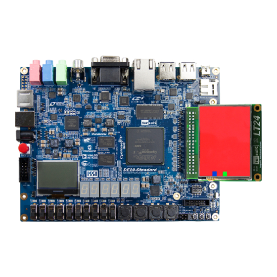
This document illustrates how to setup the LT24-Display demo on the DE10-Standard
and the LT24 as shown in
demonstration, please refer to the DE10-Standard user manual. For details about the
LT24, please refer to the user manual of LT24 daughter card.
2
.
S
y
s
t
e
m
R
2
.
S
y
s
t
e
m
R
The following items are required to perform this demonstration:
DE10-Standard and power supply
LT24 LCD touch module
3
.
E
x
e
c
u
t
e
D
3
.
E
x
e
c
u
t
e
D
Please follow the procedures below to setup the demonstration:
1. Make sure both Quartus II and USB-Blaster II driver are installed on the host
PC.
2. Power off the DE10-Standard board.
3. Connect a mini-USB cable to an UB2 port of the DE10-Standard and the host
PC.
4. Mount the LT24 onto the 2x20 GPIO (JP1) expansion header of the DE10-
Standard.
5. Power on the DE10-Standard Board.
6. Make sure Quartus Prime 16.0 Standard or later is installed on your host PC.
7. Launch
the
\DE10_Standard_LT24_Display\demo_batch
8. The RGB-Display demo should be up and running on the LCD.
DE10-Standard
LT24 Display
o
n
i
o
n
Figure
1. The basic design content is also included. In this
Figure 1 LT24 Painter Demo
e
q
u
i
r
e
m
e
n
t
s
e
q
u
i
r
e
m
e
n
t
s
e
m
o
n
s
t
r
a
t
i
e
m
o
n
s
t
r
a
t
i
"test.bat"
from
1
o
n
o
n
the
folder
demo_batch
of
www.terasic.com
March 20, 2017
the
Advertisement
Table of Contents

Related Manuals for Terasic LT24


Summary of Contents for Terasic LT24
- Page 1 2. Power off the DE10-Standard board. 3. Connect a mini-USB cable to an UB2 port of the DE10-Standard and the host 4. Mount the LT24 onto the 2x20 GPIO (JP1) expansion header of the DE10- Standard. 5. Power on the DE10-Standard Board.
- Page 2 Figure 2 shows the system block diagram of LT24-Display demonstration. LT24_Display of RTL (Verilog) code on the demo project of "/ip/lt24_display" folder. As shown Figure 2 , lt24_display the top module - lt24_display.v contains four block. Pat_update.v is used with Touch (AD7843) connection, pat_update module will...
Need help?
Do you have a question about the LT24 and is the answer not in the manual?
Questions and answers