Table of Contents
Advertisement
Quick Links
Advertisement
Table of Contents

Related Manuals for CYP CPLUS-V8PT


Summary of Contents for CYP CPLUS-V8PT
- Page 1 CPLUS-V8PT 4K UHD 2×8 HDMI Splitter Operation Manual Operation Manual...
- Page 3 DISCLAIMERS The information in this manual has been carefully checked and is believed to be accurate. Cypress Technology assumes no responsibility for any infringements of patents or other rights of third parties which may result from its use. Cypress Technology assumes no responsibility for any inaccuracies that may be contained in this document.
- Page 4 SAFETY PRECAUTIONS Please read all instructions before attempting to unpack, install or operate this equipment and before connecting the power supply. Please keep the following in mind as you unpack and install this equipment: • Always follow basic safety precautions to reduce the risk of fire, electrical shock and injury to persons.
-
Page 5: Table Of Contents
CONTENTS 1. Introduction ............1 2. Applications .............1 3. Package Contents ..........1 4. System Requirements ........2 5. Features ............2 6. Operation Controls and Functions ....3 6.1 Front Panel ..........3 6.2 Rear Panel ..........4 6.3 OSD Menu ..........5 6.4 RS-232 Control ......... 14 6.5 RS-232 Commands ........ -
Page 6: Introduction
1. INTRODUCTION This 4K UHD Switching Splitter with HDCP 2.2 is an advanced solution providing high performance audio and video support including HDR and other features defined by the HDMI 2.0a specification. 4K UHD HDMI video sources, up to and including 4K@60Hz (4:4:4, 8-bit) as well as 10/12-bit sources with HDR, are able to be passed along to the 8 outputs. -
Page 7: System Requirements
4. SYSTEM REQUIREMENTS • HDMI source equipment such as media players, video game consoles or set-top boxes. • HDMI receiving equipment such as HDTVs, monitors or audio amplifiers. • The use of “Premium High Speed HDMI” cables is highly recommended. 5. -
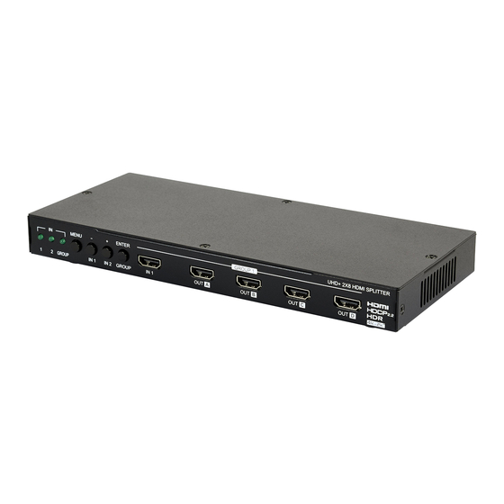
Page 8: Operation Controls And Functions
6. OPERATION CONTROLS AND FUNCTIONS 6.1 Front Panel UHD+ 2X8 HDMI SPLITTER MENU ENTER GROUP 1 GROUP IN 1 IN 2 GROUP IN 1 IN LEDs: The behavior of these LEDs depend on if Group Mode has been enabled or not. Group Mode Off IN 1~2: The illuminated LED indicates which source is currently selected. -
Page 9: Rear Panel
ENTER & GROUP: Press to confirm a selection within the OSD or to go deeper into a menu item. When not in the OSD menu, press this button to toggle Group Mode on and off. Note: Press and hold the “MENU” and “ENTER” buttons together for 3 seconds to lock or unlock the front panel. -
Page 10: Osd Menu
6.3 OSD Menu All primary functions of this unit can be controlled by using the OSD (On Screen Display) which is activated by pressing the Menu button on the front of the unit. Use the + (PLUS), − (MINUS), and ENTER buttons to navigate the OSD menu. - Page 11 Note: Auto Switch only works when Group Mode is disabled. Group Mode: Enable or disable Group Mode. MAIN MENU LEVEL 2 LEVEL 3 Input Information In1~2 [Detailed Source Information] Name Reso Freq Depth Color HDCP Audio In1~2: Show the current input’s vendor name based on the source’s info-frame data.
- Page 12 MAIN MENU LEVEL 2 LEVEL 3 Output 4K Converter Bypass To YUV420 To 1080p AUTO Out A~H Bypass To YUV420 To 1080p AUTO All: Sets the 4K conversion mode for all outputs. Setting this to bypass will disable the 4K conversion function. Note: Making changes to this setting will overwrite the individual output’s settings.
- Page 13 MAIN MENU LEVEL 2 LEVEL 3 EDID Control In 1 Int HDR MCH User 1 User 2 Copy Out A Copy Out B Copy Out C Copy Out D Copy Out E Copy Out F Copy Out G Copy Out H INT FHD 2CH In 2 Int FHD MCH...
- Page 14 MAIN MENU LEVEL 2 LEVEL 3 EDID Control Vndr [Detailed EDID Information] Name Reso Freq Depth YCbCr In 1: Assign the selected EDID to Input 1. Note: Changing the EDID may result in the source changing resolutions and blanking the output for a couple seconds. In 2: Assign the selected EDID to Input 2. Note: Changing the EDID may result in the source changing resolutions and blanking the output for a couple seconds.
- Page 15 MAIN MENU LEVEL 2 LEVEL 3 HDCP Control In 1 Apple Mode Refer Source REFER SINK In 2 Apple Mode Refer Source REFER SINK Out A~H [HDCP Status Information] In 1: Sets the HDCP mode to use with Input 1. In 2: Sets the HDCP mode to use with Input 1.
- Page 16 MAIN MENU LEVEL 2 LEVEL 3 Remote Control Link With Out A~H [OUT A] Hot Key [Button and Hot Key Assignment] Link With: Select the display to accept CEC remote control commands from to control the unit or disable the functionality. The selected display’s remote control can be used to navigate this unit’s OSD menu using the remote’s red, green, yellow and blue buttons by assigning them to the functions of the unit’s front panel...
- Page 17 MAIN MENU LEVEL 2 LEVEL 3 OSD Setting Font Color Black White Green BLUE Yellow Cyan Magenta Free Run Green BLUE Black Color Default Timeout: Set the OSD menu timeout in seconds or disable the timeout. Horizontal: Set the OSD menu’s horizontal position. Vertical: Set the OSD menu’s vertical position.
- Page 18 MAIN MENU LEVEL 2 LEVEL 3 System Setting [Vendor ID] [Product ID] [Serial Number] FW Ver [Firmware Version] Factory Reset Software Control VID: Show the unit’s Vendor ID. PID: Show the unit’s Product ID. SN: Show the unit’s Serial Number. FW Ver: Show the unit’s current firmware version.
-
Page 19: Rs-232 Control
6.4 RS-232 Control UNIT SERIAL PORT SETTINGS Pinout Pinout Baud Rate 19200 Data Bits Parity Bit None Stop Bits Flow Control None 6.5 RS-232 Commands COMMAND DESCRIPTION & PARAMETERS System Commands ? Show the full command list. HELP Show the full command list. HELP N1... - Page 20 COMMAND DESCRIPTION & PARAMETERS SET SYSTEM REBOOT Reboot the unit. SET DESCRIPTION N1 Set the description/name of the unit. N1 = {Unit Name} [Alphanumeric, 64 chars max] GET DESCRIPTION Show the unit’s current description/name. SET KEYLOCK N1 Enable or disable the front panel key lock. Available values for N1: [Enable Key Lock] [Disable Key Lock]...
- Page 21 COMMAND DESCRIPTION & PARAMETERS Valid response values are: [Not Active] [DVI Mode] [HDMI Mode] GET IN N1 COLOR SPACE Show Input N1’s current color space. N1 = 1 ~ 2 [Input Port] Valid response values are: [Not Active] [RGB] [YUV 4:4:4] [YUV 4:2:2] [YUV 4:2:0] GET IN N1 COLOR DEPTH...
- Page 22 COMMAND DESCRIPTION & PARAMETERS Available settings for N2: [Apple Mode] [Refer to Source] [Refer to Sink] GET IN N1 HDCP MODE Get Input N1’s current HDCP mode. N1 = 1 ~ 2 [Input Port] GET IN N1 HDCP STATUS Get Input N1’s current HDCP status. N1 = 1 ~ 2 [Input Port] Valid response values are:...
- Page 23 COMMAND DESCRIPTION & PARAMETERS [Copy Output B] [Copy Output C] [Copy Output D] [Copy Output E] [Copy Output F] [Copy Output G] [Copy Output H] GET IN N1 EDID Show Input N1’s current EDID mode. N1 = 1 ~ 2 [Input Port] GET IN N1 EDID DATA...
- Page 24 COMMAND DESCRIPTION & PARAMETERS SET OUT AUTO SWITCH N1 Enable or disable automatic input source switching. Available values for N1: [Auto Switch Enabled] [Auto Switch Disabled] Note: Only active when Group Mode is disabled. GET OUT AUTO SWITCH Shows the current automatic input source switching setting. SET OUT GROUP MODE N1...
- Page 25 COMMAND DESCRIPTION & PARAMETERS GET OUT N1 HPD Show the current hot-plug status of Output N1. N1 = A ~ H [Output Port] GET OUT N1 RSENSE Show the current receiver sense status of Output N1. N1 = A ~ H [Output Port] GET OUT N1 HDCP STATUS...
- Page 26 COMMAND DESCRIPTION & PARAMETERS GET USER N1 EDID DATA Show the raw hex data of the EDID stored in User EDID N1. N1 = 1 ~ 2 [User EDID Number] GET USER N1 EDID INFORMATION Show a description of the EDID stored in User EDID N1. N1 = 1 ~ 2 [User EDID Number] OSD Commands...
- Page 27 COMMAND DESCRIPTION & PARAMETERS Available values for N1: [Fully Opaque] 1 ~ 6 [Levels of Transparency] [Fully Transparent] GET OSD TRANSPARENCY Show the OSD menu’s current transparency level. SET OSD CONTRAST N Set the OSD menu’s contrast level. Available values for N1: [High Contrast] [Low Contrast] GET OSD CONTRAST...
- Page 28 COMMAND DESCRIPTION & PARAMETERS [Blue] [Yellow] [Cyan] [Magenta] GET OSD FONT COLOR Show the OSD menu’s current font color. SET OSD FREERUN COLOR N1 Set the Free Run mode and the color used when the input signal is lost and Free Run is active. Available values for N1: [Free Run Disabled] [Red]...
- Page 29 COMMAND DESCRIPTION & PARAMETERS SET CEC AUTO STANDBY N1 Enable or disable sending the CEC “standby” command to connected displays if there has been no live input source detected for more than 10 minutes. Available values for N1: [Enable Auto Standby] [Disable Auto Standby] Note: The connected display must support the CEC “standby”...
-
Page 30: Edid Management
6.6 EDID Management This unit uses an EDID Management application which allows the user to copy the EDID from an attached display, edit an existing EDID file stored on the PC or create a basic EDID from scratch. The EDID can then be uploaded to the unit for use.Please obtain the EDID Management software from your authorized dealer and save it in a directory where you can easily find it. - Page 31 • Save/Upload/Analysis: EDIDs may also be saved, uploaded or analyzed. - Save: Any EDID from the unit or a connected HDMI display can be saved to your PC as a *.bin file by selecting the EDID source from the drop-down menu and then clicking the “Save” icon.
-
Page 32: Edid Creator
6.6.2. EDID Creator • Select: Click on the “EDID Creator” tab to begin designing a new EDID from scratch (select the “New” icon), to modify an existing EDID stored on the PC as a *.bin file (select the “Load” icon) or to edit an EDID copied from the unit via the EDID Analyzer’s edit option. -
Page 33: System
Once the user is finished editing or creating an EDID it can be saved to a *.bin file locally or uploaded directly to the unit using the “Save” and “Upload” icons respectively. 6.6.3. System • Configuration & Firmware: Select the “System” tab to edit the software’s description (select the “Rename”... -
Page 34: Connection Diagram
7. CONNECTION DIAGRAM Media Player Game Console HDMI HDMI Input Input Power Supply UHD+ 2X8 HDMI SPLITTER GROUP 2 MENU ENTER GROUP 1 POWER GROUP IN 1 IN 2 GROUP IN 1 IN 2 SERVICE RS-232 DC 5V RS-232 RS-232 Controlling PC HDMI HDMI... -
Page 35: Specifications
8. SPECIFICATIONS 8.1 Technical Specifications HDMI Bandwidth 600MHz/18Gbps Input Ports 2×HDMI Output Ports 8×HDMI Control Interfaces 1×RS-232 [3-pin Terminal Block] 1×USB [Mini-B] HDMI Cable Distance 5m, 4K@60Hz (YUV 4:4:4, 8-bit) 10m, 1080p@60Hz (12-bit) 15m, 1080p@60Hz (8-bit) Power Supply 5V/3A DC (US/EU standards, CE/FCC/UL certified) ESD Protection Human Body Model:... -
Page 36: Video Specifications
8.2 Video Specifications Support Convert to Convert to Resolutions/Timing (Hz) 1080p 4:2:0 640×480p@60 640×480p@72 640×480p@75 640×480p@85 720×400p@70 720×400p@85 ... - Page 37 Support Convert to Convert to Resolutions/Timing (Hz) 1080p 4:2:0 1152×864p@85 1280×720p@23 1280×720p@24 1280×720p@25 1280×720p@29 1280×720p@30 1280×720p@50 ...
- Page 38 Support Convert to Convert to Resolutions/Timing (Hz) 1080p 4:2:0 1400×1050p@60 (RB) 1440×900p@60 1440×900p@60 (RB) 1440×900p@75 1600×900p@60 (RB) 1600×1200p@50 ...
- Page 39 Support Convert to Convert to Resolutions/Timing (Hz) 1080p 4:2:0 2048×1080p@23 2048×1080p@24 2048×1080p@25 2048×1080p@29 2048×1080p@30 2048×1080p@50 2048×1080p@59 ...
- Page 40 Support Convert to Convert to Resolutions/Timing (Hz) 1080p 4:2:0 4096×2160p@25 (4:2:2) 4096×2160p@29 (4:2:2) 4096×2160p@30 (4:2:2) 4096×2160p@50 (4:2:0) 4096×2160p@59 (4:2:0) 4096×2160p@60 (4:2:0) ...
-
Page 41: Acronyms
9. ACRONYMS ACRONYM COMPLETE TERM Consumer Electronics Control Digital Visual Interface EDID Extended Display Identification Data High-Definition HDCP High-bandwidth Digital Content Protection HDMI High-Definition Multimedia Interface High Dynamic Range LPCM Linear Pulse-Code Modulation Ultra-High-Definition Universal Serial Bus Video Graphics Array (640×480@60Hz) WUXGA Wide Ultra Extended Graphics Array (1920×1200@60Hz) - Page 44 CYPRESS TECHNOLOGY CO., LTD. www.cypress.com.tw...
Need help?
Do you have a question about the CPLUS-V8PT and is the answer not in the manual?
Questions and answers