
Related Manuals for Sega SOUL SURFER


Summary of Contents for Sega SOUL SURFER
- Page 1 1ST PRINTING JULY ‘02 Owner’s Manual SEGA ENTERPRISES, INC. USA MANUAL NO. 999-1479...
- Page 2 VISIT OUR WEBSITE!
- Page 3 BEFORE USING THE PRODUCT, BE SURE TO READ THE FOLLOWING: To maintain the safety: To ensure the safe usage of the product, be sure to read the following before using the product. The following instructions are intended for the users, operators and the personnel in charge of the opera- tion of the product.
- Page 4 SEGA shall not be held responsible for any accidents, compensation for damage to a third party, resulting from the specifications not designated by SEGA.
-
Page 5: Table Of Contents
TABLE OF CONTENTS BEFORE USING THE PRODUCT, BE SURE TO READ THE FOLLOWING: TABLE OF CONTENTS INTRODUCTION OF THE OWNER'S MANUAL 1. HANDLING PRECAUTIONS..................1 2. PRECAUTIONS CONCERNING INSTALLATION LOCATION .........3 3. OPERATION ........................5 4. NAME OF PARTS......................11 5. ACCESSORIES ......................12 6. -
Page 6: Introduction Of The Owner's Manual
STOP Indicates that mishandling the product by disregarding this display can cause the product's intrinsic performance not to be obtained, resulting in malfunctioning. IMPORTANT! SEGA ENTERPRISES, INC. (U.S.A.)/CUSTOMER SERVICE 45133 Industrial Drive, Fremont, California 94538, U.S.A. Phone: (415) 701-6580 Facsimile: (415) 701-6594... - Page 7 DEFINITION OF LOCATION'S MAINTENANCE MAN AND SERVICEMAN Non-technical personnel who do not have technical knowledge and expertise should refrain from performing such work that this manual requires the location's main- WARNING! tenance man or a serviceman to carry out, or work which is not explained in this manual.
-
Page 8: Handling Precautions
• SEGA shall not be held responsible for damage, compensation for damage to a third party, caused by specification changes not designated by SEGA. - Page 9 ● Some parts are the ones designed and manufactured not specifically for this game machine. The manufacturers may discontinue, or change the specifications of, such general-purpose parts. If this is the case, Sega cannot repair or replace a failed game machine whether or not a warranty period has expired.
-
Page 10: Precautions Concerning Installation Location
2. PRECAUTIONS CONCERNING INSTALLATION LOCATION This product is an indoor game machine. Do not install it outside. Even indoors, avoid installing in places mentioned below so as not to cause a fire, electric shock, WARNING! injury and or malfunctioning. ● Places subject to rain or water leakage, or places subject to high humidity in the proximity of an indoor swimming pool and or shower, etc. - Page 11 To avoid machine malfunctioning and a fire, do not place any obstacles near the ventilation opening. ● SEGA shall not be held responsible for damage, compensation for damage to a third party, resulting from the failure to observe this instruction.
-
Page 12: Operation
3. OPERATION PRECAUTIONS TO BE HEEDED BEFORE STARTING THE OPERATION To avoid injury and trouble, be sure to constantly give careful attention to the behavior and manner of the visitors and players. In order to avoid accidents, check the following before starting the operation: ●... - Page 13 ● Perform a test run and confirm whether the surfboard is locks and unlocks properly. WARNING! ● Be sure to take particular care to conduct the Sensor Mat input test. Failing to conduct the test and operating the machine when the Sensor Mat is not in optimum condition may cause accidents.
- Page 14 PRECAUTIONS TO BE HEEDED DURING OPERATION (PAYING ATTENTION TO CUSTOMERS) To avoid injury and trouble, be sure to constantly give careful attention to the behavior and manner of the visitors and players. ● To avoid injury and accidents, those who fall under the following categories are not allowed to play the game.
- Page 15 ● Be sure to instruct players not to wear high-heeled shoes, WARNING! as this increases the chances of an accident occurring. In addition, instruct players not to wear sneakers, sandals or other footwear that slips off easily when playing the game, as this increases the chances of an accident occurring.
- Page 16 ● Instruct the player to hold on firmly to the Safety Bar during CAUTION! game. Caution the customers who are most likely to cause injury by playing without holding the Safety Bar, for example. ● To avoid injury, do not allow persons other than the player to access to the Sensor Mat during game play.
- Page 17 ● Regarding this product, the weight of the player is limited CAUTION! to 330 lbs. To avoid machine damage and injury due to machine damage, playing by those who are as heavy as 330 lbs or heavier is strictly prohibited. Weight 330 lbs or heavier ●...
-
Page 18: Name Of Parts
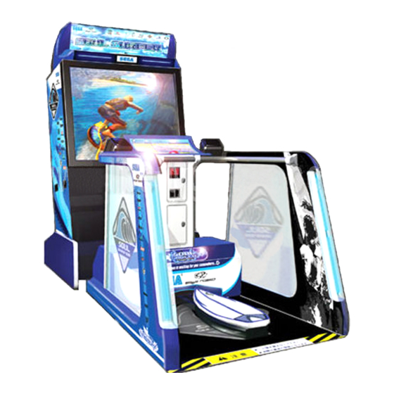
4. NAME OF PARTS BILLBOARD 50” Type Projector CONTROL PANEL COIN CHUTE DOOR CASHBOX DOOR PTV BASE SURFBOARD AC UNIT FRONT CABI REAR CABI SAFETY BAR SENSOR MAT FIG. 4 a OVERVIEW ASSY TUBE PHOTO 4 ASSY TUBE FIG. 4 b TABLE 4 Dimensions and Weights Width ×... -
Page 19: Accessories
5. ACCESSORIES When transporting the machine, make sure that the following parts are supplied. TABLE 5 ACCESSORIES DESCRIPTION KEY MASTER OWNERS MANUAL 9301A(2) Part No. (Qty.) 999-1479 (1) For opening/closing For the CASHBOX DOOR Note the doors Figures Parts not labeled with part numbers are as yet unregistered The Keys are inside the Coin or cannot be registered. - Page 20 HOW TO USE THE CARTON BOX When transporting NAOMI 2 for repair/servicing, follow the instructions below. STOP The accessory carton box is needed when transporting NAOMI 2 for repair/servicing. Be sure to safely store the Carton Box. IMPORTANT! ● When sending for repair/servicing, remove all of the wire harnesses and cables from the Filter BD in front.
- Page 21 The following Table 5b lists the parts that had been separately packed when the product was shipped from the factory but are necessary when you use the product. These parts will be mounted on the product when installing and assembling it. TABLE 5 b AC Cable (Power Cord) 600-6695-01 (1) USA...
-
Page 22: Assembling And Installation
6. ASSEMBLING AND INSTALLATION ● Perform assembly work by following the procedure herein stated. Failing to comply with the instructions can cause electric shock hazard. WARNING! ● Perform assembling as per this manual. Since this is a complex machine, er- roneous assembling can cause an electric shock, machine damage and or not functioning as per specified performance. - Page 23 When carrying out the assembly work, follow the procedure in the following 6-item sequence: ASSEMBLING THE PTV (FRONT CABI) WIRING CONNECTIONS BETWEEN THE CABINETS SECURING IN PLACE (ADJUSTER ADJUSTMENT) POWER SUPPLY, AND EARTH CONNECTION TURNING POWER ON ASSEMBLING CHECK The master key (accessories) in addition to the tools such as a Phillips type screwdriver, Box nut screwdriver and wrench are required for the assembly work.
- Page 24 ASSEMBLING THE PTV (FRONT CABI) By using the specified screws, secure the 2 Mask Holders to the PTV ceiling. Insert the TV Mask from the underside as shown and secure with a total of 6 screws. FLAT HEAD SCREW (2 each) M4×12 MASK HOLDER MASK...
- Page 25 Mount the assembled PTV on the PTV Base. After mounting the PTV, move it to the rear part of the PTV Base. When performing this work, be sure to use 4 or more persons. (FIG. 6. 1 b) Install Panel Mount Bracket L and R to the front of the PTV by using 2 screws for each of them. Connecting the 2 connectors to the connector panel PANEL MOUNT BRACKET R...
- Page 26 Install the Front Panel to the front of PTV. Use the 4 truss screws for securing. TRUSS SCREW (4),black M5×20 flat washer used. PHOTO 6. 1 b Assemble the hole lid and the front lid under the front lid. When facing the PTV screen, the hole lid is to the right and the front lid is to the left.
- Page 27 SCREW (2) black M5×16,w/flat & spring washers For performing work, use 3 workers. Connect the FIG. 6. 1 d Connector. FIG. 6. 1 e When performing work, be sure to use a step. FIG. 6. 1 f www.seuservice.com...
- Page 28 WIRING CONNECTIONS BETWEEN THE CABINETS With the ASSY Tube installed to the Front and Rear Cabinets, perform the cabinet-to-cabinet wiring. The connectors can be inserted only into those with the same number of pins, respectively, and can be inserted only in the fixed orientation. If you attempt to apply constrained force when inserting the connector, the connector or wiring may be damaged.
- Page 29 TRUSS SCREW (3),black M4×16 Install the Tube Lid of the Assy Tube to the Rear Cabinet. Attach it using the 3 screws. Be careful not to pinch the wiring. PHOTO 6. 2 c Locate the Front and Rear Cabinets close to each other. If you apply too much force when joining the connectors, the wiring may be damaged.
- Page 30 Join the connector of the Assy Tube to the connector of the Front Cabinet. Join the connectors to those with the same number of pins, respectively. Connect the 6 Connectors. PHOTO 6. 2 e TRUSS SCREW (4),black M4×16 Install the Tube Lid of the Assy Tube to the Front Cabinet.
- Page 31 SECURING IN PLACE (ADJUSTER ADJUSTMENT) Make sure that all of the adjusters are in contact with the floor. If they are not, the cabinet can move and cause an accident. WARNING! Be careful to store the shipping beam as it is used when moving the rear cabinet with a forklift.
- Page 32 Reinsert these four hexagon-head bolts into their original holes. Reinsert the hexagon-head bolt (2 each on both sides) into the original hole. PHOTO 6. 3 b Make sure all of the adjusters are in contact with the floor. By using a wrench, change height of the adjusters to ensure that the machine's position is level.
- Page 33 After making adjustments, fasten the adjuster nut upward and secure the height of the adjuster. (FIG. 6.3b) ADJUSTER CASTER FASTEN UPWARD. Approx..75 inches ADJUSTER FIG. 6. 3 b ADJUSTER 6 inches 5.1 inches FIG. 6. 3 d FIG. 6. 3 c Be sure to provide space as shown between the Air Vent and the wall Refer to this Fig.
- Page 34 Pass the wire through the corner hole. MAT HOLDER FRONT HEXAGON NUT (2 each) M4, flat washer used. PHOTO 6. 3 d Assemble the mat holder fronts in the same way on the side of the Sensor Mat without wires. PHOTO 6.
- Page 35 Attach the mat holder fronts to the rear cabinet. Secure it to each one with two screws. Be careful not to pinch the wires at this time. SCREW (2 each) M5×8, w/flat & spring washers PHOTO 6. 3 g Connect the Sensor Mat wire connectors to the connectors to the undersurface of the rear cabinet. (FIG.
- Page 36 Attach the mat wire cover to the mat holder fronts and secure it with two truss screws. Assemble a mat wire cover in the same way on the side of the Sensor Mat without wires. MAT WIRE COVER TRUSS SCREW (2 each), black M4×16 PHOTO 6.
- Page 37 Attach the Mat Bracket L and R to the left and right rear of the mat holder. Secure each with two hexagon-head bolts. Assembling the mat brackets cause the rear of the mat holder to restrain the Sensor Mat. The left and right mat brackets are different. Confirm their assembly locations and directions before assembling.
- Page 38 POWER SUPPLY, AND EARTH CONNECTION ● Be sure to independently use the power supply socket outlet equipped with an Earth Leakage Breaker. Using a power supply without an Earth Leakage WARNING! Breaker can cause a fire when electric leakage occurs. ●...
- Page 39 *Note that the Earth Wire is incorporated in Connect the Earth Wire to the Earth Terminal. the Power Cord for the Areas of AC 120V (USA) and AC 220 ~ 240V, and therefore, this procedure is not necessary. FIG. 6. 4 b *Earth Wire Connection <EXCEPT USA> Firmly insert the power plug into the socket outlet.
- Page 40 TURNING POWER ON Turn on the AC unit main switch to power on the machine. Once it is powered on, the Billboard fluorescent lamp and the four Cold-Cathode Tubes to the left and right of the Rear Cabinet light up. After several seconds, the screen changes to the Advertise Screen, which is in the wait-for-guest mode (Advertise Mode).
- Page 41 ASSEMBLING CHECK In the TEST MODE, ascertain that the assembly has been made correctly and IC BD. is satisfactory (refer to Section 9). In the test mode, perform the following test: 1 MEMORY TEST Selecting the RAM TEST on the system test mode menu screen causes the on-board memory to be tested automatically.
- Page 42 3 SOUND TEST In the system test mode, selecting SOUND TEST causes the screen (on which sound re- SOUND TEST lated BD and wiring connections are tested) to be displayed. RIGHT SPEAKER Check if the sound is satisfactorily emitted LEFT SPEAKER from each speaker and the sound volume is ->...
-
Page 43: Precautions To Be Heeded When Moving The Machine
7. PRECAUTIONS TO BE HEEDED WHEN MOVING THE MACHINE ● When moving the machine, be sure to unplug the power plug. Moving the machine with the plug as is inserted can damage the power cord and cause fire WARNING! and electric shock hazards. ●... - Page 44 ● When transporting the product in places with steps, disassemble into each unit STOP before transporting. Inclining the product in an as is assembled condition or placing the cabinet in places with steps can damage the unit's joining portions. IMPORTANT! ●...
- Page 45 When transporting the product in places with steps or step-like differences in grade, disassemble into each unit before transporting. GRIP Remove the Sensor Mat and the Mat Holder Rear when moving the machine. FIG. 7 b Do not hold or press these hatched parts to move the product.
-
Page 46: Game Contents
8. GAME CONTENTS The following explanations apply to the case the product is functioning satisfactorily. Should there be any moves different from the following contents, some sort of faults may have occurred. Immediately look into the cause of the fault and eliminate the cause thereof to ensure satisfactory operation. - Page 47 Controls Start Button (Includes: Input/Restart) Select Button Surfboard Surfboard Movements Left/Right Swing Left/Right Roll Back Pitch Basic Turns Turn Assist Perform Action Players swing the board left and right to turn. Turning power changes according to the amount of swing. By leaning into a roll during a turn, players can make sharper turns.
- Page 48 Selecting a Surfer and a Course After inserting enough coins for one player, press the Start Button to start the game. CHARACTER SELECT HAWK Select: & Confirm: NAME : HAWK STANCE : REGULAR HOME : CALIFORNIA SPONSOR : Choose one of the four surfers. FOX is the only goofy-footed (left-handed) character. Move the cursor with the Select Button to select the character, and press the Start Button to input the choice.
- Page 49 Courses There are two courses (and some additional material). Each course is composed of four stages. Players can play a bonus stage (Staff Roll) after clearing the final stage of the HARD course only. Easy Course ❏ ”California” The shape of the waves hardly changes at all, making this an appropriate introductory stage for practicing turn tricks and air tricks.
- Page 50 Current Trick and Grade Time Remaining Points Required to Clear Points to Clear Current Number of Con- 32" secutive Combos 5000 pts. × COMBO 1270 Off The Lip Current Trick Score (Multiplied by the number of combos) Tube Ride Off The Lip Ollie Stage Score Air Take Off...
- Page 51 Stage Result Screen STAGE CLEAR 6236 Stage Score pts. 12700 Total Score pts. BEST COMBO × Your Rank A screen displaying a player evaluation for the stage will appear after each stage has been completed. The ranking is based on: ❍...
- Page 52 Total Result Screen RESULT 12700 Total Score pts. 4'00"00 Total Time 4 / 4 Cleared Stage Your Rank A screen displaying a total player evaluation for game play will appear after the game has been ended. The average rank of plays completed at that point will be displayed as "YOUR RANK". The six grade levels are E, D, C, B, A, and S, with S as the highest rank.
- Page 53 Name Entry A display for entering three initials will be displayed at the following times: When all of stages of a course have been cleared. When a player has placed in the high scores of the game machine (up to the top 44 names) When a player has beaten the high score of any of the four stages (or additional material) of each course Players select letters to enter by scrolling through the character columns with the Select Button and...
- Page 54 Game Flow Character Select Course Select EASY 1-3 stage only Controller Explanation Stage Preview Screen Continue Stage Migration Screen Game Stage has been cleared Stage Result Screen Continue Screen Stage has not been cleared All HARD stages have been cleared Do not continue Staff Roll Stage Result Screen...
- Page 55 Executing Tricks Takeoff Players can delay the timing of their takeoffs by stomping on the back of the board while the character is paddling (paddling to advance the surfboard). Points are awarded even if takeoff is delayed only a little, but the player will wipeout by delaying takeoff too much. Executable Tricks Late Takeoff (slightly delayed takeoff) (E Grade) ■...
- Page 56 Executable Tricks (HAWK) Surfing to the right of the wave: ■ “Kickflip” (D Grade) ■ “Ollie Method” (C Grade) ■ “Mute Tailpoke” (B Grade) ■ “Varial Heelflip Indy Grab” (A Grade) ■ “Ollie McTwist” (S Grade) Surfing to the left of the wave: ■...
- Page 57 Turn Tricks Players can execute turn tricks by surfing out the flat part of the wave, then climbing the face of the wave, jumping off at the last minute and stomping hard on the back of the board while swinging to reverse direction.
- Page 58 Other Turn Tricks ■ 360 (D Grade) All turn tricks are performed by swinging the board to reverse direction an stomping on the back of the board, but players can execute the "360" trick by stomping on the back of the board with the swing entered in the forward direction.
- Page 59 Other Special Tricks ■ Ollie (E Grade) Stomp on the back of the board while surfing the wave incline to perform and Ollie (jump). ■ Reverse (E Grade) Players can perform a reverse and continue surfing reversed by landing backward after an Ollie or other air trick.
- Page 60 ■ Edge Ride (S Grade) Players can descend along with a wave edge (Edge Ride) by surfing in parallel with the crest of a wave ahead and stopping on the back of the board the moment it breaks. Stomp on the back of the board the moment it breaks ahead www.seuservice.com...
-
Page 61: Explanation Of Test And Data Display
9. EXPLANATION OF TEST AND DATA DISPLAY By operating the switch unit, periodically perform the tests and data check. When installing the ma- chine initially or collecting cash, or when the machine does not function correctly, perform checking in accordance with the explanations given in this section. The following shows tests and modes that should be utilized as applicable. - Page 62 TABLE 9 EXPLANATION OF TEST MODE ITEMS DESCRIPTION REFERENCE SECTIONS INSTALLATION When the machine is installed, perform the following: OF MACHINE 1. Check to see that each setting is as per standard setting made at 9-3D, E the time of shipment. 2.
- Page 63 9 - 1 SWITCH UNIT AND COIN METER STOP ● Adjust the sound to the optimum volume, taking into consideration the envi- ronmental requirements of the installation location. IMPORTANT! ● If the COIN METER and the game board are electrically disconnected, game play is not possible.
- Page 64 9 - 2 SYSTEM TEST MODE ● The contents of settings changed in the TEST mode are stored when the test STOP mode is finished from EXIT in the menu mode. If the power is turned off be- fore the TEST mode is finished, the contents of setting change become ineffec- IMPORTANT! tive.
- Page 65 9 - 3 GAME TEST MODE ● When changing the game configuration, changes will not be enabled until the STOP Game Test Mode has been completed. Be sure to exit the Game Test Mode properly after configuration changes. IMPORTANT! ● Do not configure the game in ways not described in this text, as this may lead to game malfunctions.
- Page 66 B. INPUT TEST ● Entering this mode unlocks the surfboard. It will automatically return to center and move in the direction of the load. Be careful so as to avoid accidents such CAUTION! as falling from the surfboard or allowing it to hit your legs. ●...
- Page 67 Input values related to the surfboard will change in real time. Confirm that the values change smoothly in response to motion of the board. Press the SERVICE and TEST Buttons simultaneously to return to the Game Test Menu screen. Recommended Display Values ● BOARD SWING 7 0 H ~ 9 0 H ● BOARD ROLL 7 0 H ~ 9 0 H...
- Page 68 C. OUTPUT TEST Entering this mode unlocks the surfboard. It will automatically return to center and move in the direction of the load. Be careful so as to avoid accidents such as falling from the surfboard or allowing it to hit your legs. CAUTION! Select OUTPUT TEST to display the following screen and check the status of each lamp.
- Page 69 D. GAME ASSIGNMENTS Select GAME ASSIGNMENTS to display the current game settings and make changes. GAME ASSIGNMENTS GAME DIFFICULTY NORMAL CONTINUE DEFAULT CHARA HAWK DOLPHIN BOARD DEFAULT SETTING > EXIT SELECT WITH SERVICE BUTTON PRESS TEST BUTTON FIG. 9. 3 d GAME ASSIGNMENTS Screen ●...
- Page 70 DEFAULT CHARA: ● This sets the first character to be used after the start of the game. Choose from HAWK/VIPER/FOX/DAISY. The default value is HAWK. DOLPHIN BOARD: ● This enables or disables the use of the hidden character DOLPHIN RIDER. If set to ON, DOLPHIN RIDER can be selected by inputting a command at the character select screen.
- Page 71 E. CALIBRATION When entering this mode to adjust the volume settings, be aware that pressing the Service Button will unlock the surfboard. The board will automatically return to CAUTION! center and move in the direction of the load. Be careful so as to avoid accidents such as falling from the surfboard or allowing it to hit your legs.
- Page 72 Volume Calibration When setting volume calibration, first press the SERVICE Button. The surfboard will unlock, so be careful. Part of the screen display will change as follows. CALIBRATION BOARD SWING RIGHT C0 LEFT 40 CENTER 80 BOARD ROLL RIGHT C0 LEFT 40 CENTER 80 BOARD PITCH REAR 40...
- Page 73 F. BOOKKEEPING Select BOOKKEEPING to display the following screens of operating status data. Pressing the TEST button toggles between the first (BOOKKEEPING 1/2) and second (BOOKKEEPING 2/2) screens. BOOKKEEPING 1/2 NUMBER OF GAMES PLAY TIME 0D 0H 0M 0S AVERAGE PLAY TIME 0H 0M 0S LONGEST PLAY TIME 0H 0M 0S...
- Page 74 G. BACKUP DATA CLEAR Select BACKUP DATA CLEAR to clear the contents of BOOKKEEPING and Ranking Data. BACKUP DATA CLEAR YES(CLEAR) > NO(CANCEL) SELECT WITH SERVICE BUTTON PRESS TEST BUTTON FIG. 9. 3 g BACKUP DATA CLEAR Screen To clear data, use the SERVICE Button to move the cursor to YES (CLEAR) and then press the TEST Button.
-
Page 75: Maintenance Of Surfboard Mechanism Unit
10. MAINTENANCE OF SURFBOARD MECHANISM UNIT ● Before starting to work, ensure that the Power SW is OFF. Failure to observe this can cause electric shock or short circuit. WARNING! ● Use care so as not to damage wirings. Damaged wiring can cause electric shock or short circuit. - Page 76 ADJUSTING PROCEDURE Turn of the power. Remove the four screws that secure the volume lid under the cache box door and remove the volume lid. VOLUME LID TRUSS SCREW (4), black M4×10 PHOTO 10. 1 a There is a Metal Plate behind the Volume Lid.
- Page 77 Loosen the two screws that secure the unit. Be careful not to loosen them too much at this time. The screws may fall into the interior of the cabinet if removed. SCREW (2), black M4×12, w/flat & spring washers PHOTO 10. 1 c Remove the SWING VR unit.
- Page 78 Tighten the two loosened screws after performing the adjustment. Install the SWING VR unit in its original position. Install the VR guide so that it straddles the interior shaft and secure it by tightening the two loosened screws. SHAFT PHOTO 10. 1 f Connect the connector and secure the wiring with the cord clamp.
- Page 79 Remove the hexagon nuts that secure the volumes to the VR plate and remove them from the VR plate. VOLUME 220-5484 PHOTO 10. 1 h The wiring attached to the volumes is used as is. Cut the connection areas with the nippers. PHOTO 10.
- Page 80 Pass each of the included heat- shrinkable tubes through to the wiring. Insert the wire into heat-shrinkable tube. PHOTO 10. 1 k Solder the wires to the terminal posts of the volumes to be replaced. Check the wiring diagram and be careful not to solder the wrong wires.
-
Page 81: Adjustment/Replacement Of The Roll Direction Volume
10 - 2 ADJUSTMENT/REPLACEMENT OF THE ROLL DIRECTION VOLUME The surfboard ROLL motion (tilt) detector volume is located to the interior of the bellows under the rear of the surfboard. PITCH DETECTION VOLUME ROLL DIRECTION VOLUME PHOTO 10. 2 a The following tools are required for the operations below: an M4 screw Phillips screwdriver, a hexagonal wrench with an opposite side distance of 1.5 millimeters, an adjustable spanner with an opposite side distance of 10 to 11 millimeters, nippers, cutters, a wire stripper, a soldering iron and an... - Page 82 Remove the one screw from the lower rear surface of the surfboard. SCREW (1), black M4×12, w/flat & spring washers PHOTO 10. 2 c Remove the catch from the bellows and remove the tail lid from the surfboard. TAIL LID Remove the three screws from each of the bellows sashes and PHOTO 10.
- Page 83 Lift the bellows to be able to see the ROLL VR unit. Loosen the two screws that secure the ROLL VR unit and adjust the gear engagement. When the surfboard is level to the ground, engage the gears so that the D-cut face of the volume axle is arranged as shown in Figure 10.2. PHOTO 10.
- Page 84 REPLACING PROCEDURE Perform the operations listed in "Adjustments" 1 through 6, listed above. Loosen the harness lug that secures the wiring and remove the connector from the bottom right side of the surfboard. CONNECTOR (1) PHOTO 10. 2 g Remove the two screws and remove the ROLL VR unit.
- Page 85 Loosen the two hexagon socket screws that secure the gears and remove the gears from the volume axle. HEXGAON SOCKET SCREW (2) M3×6 PHOTO 10. 2 i Remove the hexagon nuts that secure the volume to the VR bracket and remove it from the VR bracket.
- Page 86 Attach the volume to the VR bracket and secure the gears to the volume axles. Install the ROLL VR unit. At this time, assemble it so that the gears engage as explained in "Adjustments" 6 and 7, listed above. Secure the wiring with harness lugs after connecting the connector.
-
Page 87: Pitch Detection Volume Replacement
10 - 3 PITCH DETECTION VOLUME REPLACEMENT The surfboard's PITCH detection volume is located to the interior of the bellows under the surfboard to the rear. The following tools are required for the operations below: an M4 screw Phillips screwdriver, a hexagonal wrench with an opposite side distance of 1.5 millimeters, an adjustable spanner with an opposite side distance of 10 to 11 millimeters, nippers, cutters, a wire stripper, a soldering iron and an industrial dryer. - Page 88 Loosen the two hexagon socket screws that secure the VR guide and remove the VR guide from the volume axle. HEXAGON SOCKET SCREW (2) M3×6 PHOTO 10. 3 c Remove the hexagon nuts that secure the volume to the VR bracket and remove the VR bracket.
- Page 89 PAttach the PITCH VR unit so that the pin is inserted into the VR guide notch. Connect the connectors and secure the wiring with the two harness lugs. PHOTO 10. 3 e Turn on the power and perform calibration in TEST MODE. (Refer to 9-3 E.) At this time, be especially careful that the VR guide rotates smoothly in line with operation and that the interior constituent parts will not damage the wiring.
-
Page 90: Greasing
10 - 4 GREASING ● Grease is inflammable and must never be close to fire. ● Grease may be apt to be erroneously used or drunk, and must not be placed in WARNING! a location where children can access. ● Grease does harm to your body if you aspirate it. Do not perform any work related to grease in a location where ventilation is insufficient. - Page 91 ROLL VR UNIT PITCH VR UNIT PHOTO 10. 4 c VR GUIDE SLIDING PORTION PHOTO 10. 4 b GEAR MESH PORTION GREASING UP THE SWING MECHANISM The rear cabinet must be moved in order to grease up the SWING mechanism for the surfboard lock.
- Page 92 Attach the extension tube to the spray grease nozzle and spray grease on the gear mesh portion. PHOTO 10. 4 e www.seuservice.com...
-
Page 93: Replacing The Bellows
10 - 5 REPLACING THE BELLOWS Be sure to replace abnormal hazard preventive parts immediately. Failure to observe this may cause accidents. WARNING! The bellows beneath the surfboard is a part essential to the prevention of accidents. Be sure to inspect in before commencing operation and replace it immediately if torn. - Page 94 Remove the nose lid from the front of the surfboard. Remove the two screws. SCREW (2), black NOSE LID M4×8, w/flat & spring washers PHOTO 10. 5 c PHOTO 10. 5 d Remove the eight hexagon nuts from the bottom of the surfboard. This is the pairing of the carriage bolts and hexagon nuts other than for the two areas to the front of the surfboard.
- Page 95 Remove the surfboard by lifting it straight up. SURFBOARD PHOTO 10. 5 g Remove each pair of hexagon-head bolts and remove the two board holders. BOARD HOLDER PHOTO 10. 5 i PHOTO 10. 5 h HEXAGON-HEAD BOLT (2 each) M8×30, w/spring washer www.seuservice.com...
- Page 96 Remove the ASSY board from the SWING mechanism. The bellows are attached below the wooden board of the ASSY board. ASSY BOARD PHOTO 10. 5 j BELLOWS PHOTO 10. 5 k Remove each set of three screws and remove the left and right bellows holder sides.
- Page 97 Remove each pair of screws and remove the front and back bellows holders. PHOTO 10. 5 n SCREW (2 each) M4×16, w/flat & spring washers BELLOWS HOLDER Remove and replace the damaged bellows. Attach the bellows "seam" to the wooden board so that comes to the front.
-
Page 98: Projector
PROJECTOR Since the Projector has been adjusted at the time of shipment, avoid making further adjustments without good reason. WARNING! The Projector is subject to color deviation due to Convergence deviation caused STOP by the geomagnetism at the installation location and peripheral magnetic field. After the installation of machine, and before commencing operation, check for IMPORTANT! Convergence deviation and if deviated, make adjustments. -
Page 99: Projector Adjustment
11 - 2 PROJECTOR ADJUSTMENT SETTING THE INTERFACE In this product, set to INPUT LEVEL: 0.7V and IMPEDANCE: 75Ω. Failure STOP to observe this can cause CRT membrane to burn or Shutdown device to function resulting in power off. IMPORTANT! The Projector's Connector Panel contains the Interface setting SW. - Page 100 AUTOMATIC COLOR MATCHING The Projector may be subject to color deviations affected by earth magnetism, the building steel frames, etc. When the Projector is initially installed or the Projector's installation position is changed, have the color matching performed automatically. Keep pressing the P button (red) for approximately 3 seconds to have the ensuing movements performed automatically.
- Page 101 ADJUSTING THE ON-SCREEN CONTRAST Although the on-screen picture quality has been adjusted at the time of shipment from the factory, the on-screen contrast can be readjusted if desired. When the Game Board is replaced, readjustment may be necessary. Changing the CONTRAST causes the light and shade of the on-screen images to be changed.
- Page 102 ADJUSTING THE SCREEN BRIGHTNESS Although the on-screen picture quality has been adjusted at the time of shipment from the factory, readjustment can be made if desired. When the Game Board is replaced, readjustment may be neces- sary. Changing the BRIGHTNESS causes the brightness of the on-screen images of black portions to be changed.
- Page 103 ADJUSTING THE ON-SCREEN DISPLAY POSITION Although the on-screen display position (H. POSI, V. POSI) has been adjusted at the time of ship- ment from the factory, readjustment can be made if desired. When the Game Board is replaced, readjustments may be necessary. Press either ...
- Page 104 ADJUSTING THE SCREEN SIZE Although the on-screen size (H. SIZE, V. SIZE) has been adjusted at the time of shipment from the factory, readjustment can be made if desired. When the Game Board is replaced, readjustments may be necessary. Press either or PIC - ADJ button. The on-screen menu will have one PIC-ADJ CONTRAST...
- Page 105 CONVERGENCE ADJUSTMENT (manual color matching) To avoid circuitry malfunctioning due to electrical load increase, never utilize CONVERGENCE ADJUSTMENT (Line Convergence Adjustment in particular) for adjusting screen size changes. CAUTION! There is no means to restore the Convergence Adjustment data once stored, to its original state.
- Page 106 STATIC CONVERGENCE ADJUSTMENT In the static convergence adjustment, each of red and blue images is comprehensively moved to and superimposed on the green color. If automatic color matching function is not sufficiently satisfac- tory, perform this adjustment. Be sure to perform automatic color matching before starting the above adjustment.
- Page 107 POINT CONVERGENCE ADJUSTMENT In the POINT CONVERGENCE adjustment, each of red, green and blue images is partially moved for color matching. The adjustment may be necessary when the Game Board is replaced or changed, or screen size is changed. Be sure to perform automatic color matching before starting the adjustment. Keep pressing the TEST button for approximately 3 seconds.
- Page 108 LINE CONVERGENCE ADJUSTMENT In the LINE CONVERGENCE ADJUSTMENT, the adjustment point of the column line (vertical) or row line (horizontal) is comprehensively moved for color matching. It is convenient to utilize this adjustment when the color of the column line or row line is uniformly deviated. Keep pressing the TEST button for approximately 3 seconds.
-
Page 109: Coin Selector
12. COIN SELECTOR HANDLING THE COIN JAM If the coin is not rejected when the REJECT button is pressed, open the coin chute door and open the selector gate. After removing the jammed coin, put a normal coin in and check to see that the selector correctly functions. - Page 110 www.seuservice.com...
- Page 111 www.seuservice.com...
- Page 112 OPTIONAL DOLLAR BILL ACCEPTOR ● THE COIN DOOR ASSEMBLY USED ON SOUL SURFER COMES EQUIPPED TO ACCEPT A DOLLAR BILL ACCEPTOR. ALL NEEDED WIRING CONNECTIONS ARE CONVENIENTLY LOCATED INSIDE THE GAME FOR THIS APPLICATION. ● THE COIN DOOR CAN ACCOMMODATE THE FOLLOWING...
-
Page 113: Replacing The Fluorescent Lamp, And Lamps
13. REPLACING THE FLUORESCENT LAMP, AND LAMPS ● When performing work, be sure to turn power off. Working with power on can cause electric shock and short circuit hazards. WARNING! ● The Fluorescent Lamp, when it gets hot, can cause burn. Be very careful when replacing the Fluorescent Lamp. - Page 114 Draw out the Billboard Plate toward you. BILLBOARD PLATE PHOTO 13 b Replace the fluorescent lamps. FLUORESCENT LAMP (2 qty)12w 15” GLOW LAMPS PHOTO 13 c START BUTTON LAMP Turn off the power. Remove the 6 truss screws securing the Control Panel Plate. TRUSS SCREW (4) M4×16,chrome plated TRUSS SCREW (2)
- Page 115 Remove the Control Panel Plate. The Control Panel Plate contains wiring connections. Remove this panel, taking care not to damage the wiring. CONTROL PANEL PLATE PHOTO 13 e LAMP 6V 3W(WEDGE BULB) Hold both sides of the switch portion with 390-5160 fingers and pull out from the button's base portion.
- Page 116 Be careful of the strength and direction of cover removal when removing the lamp covers from the wall. Removing the lamp covers without care may damage them. LAMP COVER PHOTO 13 g * Remove the truss screws (four in all) that secure the lamp units. There is one pair above and another pair below.
- Page 117 Remove the lamp units from the wall. There are wiring connections to the interior, so be careful. Bring the lamp units down slowly until the two connectors can be seen. Remove the connectors. LAMP UNIT CONNECTOR (2) PHOTO 13 i * Remove tube holder B from the center of the lamp units.
- Page 118 Remove tube holder A from the side of the Light Rope to be replaced. Remove the two truss screws. Then remove the upper bracket of the Light Rope to be replace and the lower bracket. TUBE HOLDER A PHOTO 13 m * TRUSS SCREW (2) PHOTO 13 l * M4×8, chrome plated...
- Page 119 LIGHT ROPE SOLID STATE RELAY BD Any trouble of turning on/off a Light Rope may be due to breakage of the Solid State Relay BD (SSR BD) for the Light Rope as well as the end of the safe useful life or failure of the lamp unit itself. On its backside, the lamp unit is equipped with the SSR BD for the respective Light Rope.
- Page 120 Disconnect the connectors attached to the SSR Bds. Relay BD For Upper Light Rope Disconnect the connector. Relay BD For Lower Light Rope PHOTO 13 q Remove the four screws that secure each board and replace the board. Then replace the cage (SSR BD Cover) over the two SSR BD.
-
Page 121: Periodic Inspection Table
14. PERIODIC INSPECTION TABLE The items listed below require periodic check and maintenance to retain the performance of this ma- chine and to ensure safe business operation. ● Be sure to check once a year to see if Power Cords are damaged, the plug is securely inserted, dust is accumulated between the Socket Outlet and the WARNING! Power Plug, etc. -
Page 122: Troubleshooting
15. TROUBLESHOOTING ● In order to prevent electric shock and short circuit, be sure to turn power off before performing work. WARNING! ● Be careful so as not to damage wirings. Damaged wiring can cause electric shock or short circuit. ●... - Page 123 TABLE 15 b PROBLEMS CAUSE COUNTERMEASURES Fluorescent Lamp Poor connection of connector in the Billboard. Accurately connect the connector (see Sec. 6). does not light up. Fluorescent lamp need replacement. Replace Fluorescent Lamp (see Sec. 13). The Cold-Cathode Connection fault of connector between Front & Accurately connect the connector (see Sec.
-
Page 124: Game Board
16. GAME BOARD ● In order to prevent electric shock and short circuit hazards, be sure to turn power off before performing work. WARNING! ● Be careful so as not to damage wirings. Damaged wiring can cause fire, electric shock and short circuit hazards. ●... - Page 125 Unlock and remove the Back Door. PHOTO 16. 1 b There is a game board (NAOMI 2 Board) above the wooden board of the ASSY MAIN board to the interior of the back door. Disconnect all of the connectors that are connected to the game board.
-
Page 126: Composition Of Game Board
16 - 2 COMPOSITION OF GAME BOARD ASSY CASE NAT SSF USA 840-0095D-01 USA TRUSS SCREW (4) M3×30,chrome plated ROM CASE NAT SSF 840-0095C DIP SW ASSY CASE NAOMI2 MAIN BD USA / 840-0046A-01 : USA FIG. 16. 2 a DIP SW SETTING In this product, set all of the DIP SWes to OFF. -
Page 127: Design Related Parts
17. DESIGN RELATED PARTS For the Warning Display stickers, refer to Section 1. www.seuservice.com... -
Page 128: Parts List
18. PARTS LIST � ������������ � �������� ����������� � ������� � �������� � �������� ������������������ �������� � �������� � �������� �������������� �������������� � �������� �� �������� ������������������ ������������������ � �������� �� �������� �� �������� ��������������� ������������ ����������������� �� �������� �� �������� ���������... - Page 129 1 TOP ASSY SSF (D-1/3) www.seuservice.com...
- Page 130 1 TOP ASSY SSF (D-2/3) ITEM NO. PART NO. DESCRIPTION NOTE SSF-0100 ASSY FLOOR MAT SSF-0200 ASSY SHIPPING BEAM SSF-1000 ASSY FRONT CABI SSF-1200 ASSY PTV SSF-3000 ASSY REAR CABI ATR-1300 ASSY FRONT PANEL SSF-0003 FRONT LID SSF-0004 MAT BRKT L SSF-0005 MAT BRKT R SSF-0006...
- Page 131 CAUTION INSTR COP U/R 421-6690-01 STICKER 120V <AC 120V Area> 421-6690-03 STICKER 220V <AC 220V Area> 421-6690-06 STICKER 110V <AC 110V Area> 421-6690-05 STICKER 240V <AC 240V Area> 421-6119-91 STICKER FCC <USA> 421-6120-93 STICKER SEGA USA <USA> 421-7308-~ DENOMI SH 1GAME~ www.seuservice.com...
- Page 132 2 ASSY FLOOR MAT (SSF-0100) (D-1/2) www.seuservice.com...
- Page 133 2 ASSY FLOOR MAT (SSF-0100) (D-2/2) ITEM NO. PART NO. DESCRIPTION NOTE SSF-0101 MAT SW SSF-0102 MAT CONN PART SSF-0103 MAT TARMINAL 999-1480 MAT REINFORCEMENT PLATE LEFT 999-1481 MAT REINFORCEMENT PLATE RIGHT 000-P00320-W M SCR PH W/FS M3×20 050-F00300 FLG NUT M3 000-T00408 M SCR TH M4×8 SSF-60050...
- Page 134 3 ASSY SHIPPING BEAM (SSF-0200) (D-1/2) www.seuservice.com...
- Page 135 3 ASSY SHIPPING BEAM (SSF-0200) (D-2/2) ITEM NO. PART NO. DESCRIPTION NOTE SSF-0201 SHIPPING BEAM SSF-0202 SHIPPING BEAM BRKT SSF-0203 SHIPPING SPACER 030-000820-S HEX BLT W/S M8×20 068-852216 FLT WSHR 8.5-22 ×1.6 000-P00520-W M SCR PH W/FS M5×20 www.seuservice.com...
- Page 136 4 ASSY FRONT CABI (SSF-1000) (D-1/2) www.seuservice.com...
- Page 137 4 ASSY FRONT CABI (SSF-1000) (D-2/2) ITEM NO. PART NO. DESCRIPTION NOTE SSF-1001 ASSY SUBCABI FRONT SSF-4000 ASSY MAIN BD SSF-4100 ASSY XFMR 421-11416 STICKER CAUTION FORK 000-P00530-S M SCR PH W/S M5×30 068-552016 FLT WSHR 5.5-20 ×1.6 000-P00630 M SCR PH M6×30 060-S00600 SPR WSHR M6 068-652016...
- Page 138 5 ASSY SUBCABI FRONT (SSF-1001) (D-1/2) www.seuservice.com...
- Page 139 5 ASSY SUBCABI FRONT (SSF-1001) (D-2/2) ITEM NO. PART NO. DESCRIPTION NOTE SSF-1002 BASE CABINET SSF-1030 ASSY WOOFER ATR-1050 AC UNIT ATR-1060 FAN UNIT ATR-1070 ASSY BACK DOOR ASK-1152 LOCK BRKT ARC-1006 LEG BRACKET 117-5233 PLATE LEG BRACKET BLACK 253-5460-01 AIR VENT BLACK 117-5402-06-91 EARTH TERMINAL PLATE 6P...
- Page 140 6 ASSY WOOFER (SSF-1030) ITEM NO. PART NO. DESCRIPTION NOTE SSF-1031 WOOFER BRKT 130-5097 SPEAKER BOX SUPER WOOFER 209-0023 CONN CLOSED END 011-T03512 TAP SCR TH 3.5×12 SSF-60029 WH WOOFER www.seuservice.com...
- Page 141 7 AC UNIT (D-1/2) ITEM NO. PART NO. DESCRIPTION NOTE JBA-1031 AC BRKT 421-7468-01 STICKER C.P W/PIC 214-0202 AC INLET PANEL TYPE 512-5046-8000 C.P 8000MA CE UL <AC 110-120V Area> 512-5046-5000 C.P 5000MA CE UL <AC 220-240V Area> 509-5453-91-V-B SW ROCKER J8 V-B www.seuservice.com...
- Page 142 8 FAN UNIT (ATR-1060) Connector ITEM NO. PART NO. DESCRIPTION NOTE ATR-1061 FAN BRKT 260-0011-02 AXIAL FLOW FAN AC100V 50-60HZ 601-8543 FAN GUARD 000-P00312-W M SCR PH W/FS M3×12 www.seuservice.com...
- Page 143 9 ASSY BACK DOOR (ATR-1070) ITEM NO. PART NO. DESCRIPTION NOTE ATR-1071 BACK DOOR TH-1015 LOCKING TONGUE 253-5460-01 AIR VENT BLACK 220-5575 CAM LOCK MASTER W/O KEY 000-T00408-0B M SCR TH BLK M4×8 www.seuservice.com...
- Page 144 10 ASSY WIRE FRONT DC (SSF-6002) This is comprised of the following wire harnesses. ASSY drawing is not available. ITEM NO. PART NO. DESCRIPTION NOTE 601-0460 PLASTIC TIE BELT 100 MM SSF-60016 WH EXT WOOFER SSF-60023 WH EXT SOUND FRONT SSF-60024 WH EXT TOWER FRONT SSF-60025...
- Page 145 11 ASSY MAIN BD (SSF-4000) (D-1/2) www.seuservice.com...
- Page 146 11 ASSY MAIN BD (SSF-4000) (D-2/2) ITEM NO. PART NO. DESCRIPTION NOTE SSF-4001 MAIN BD BASE APC-4002 SW REGU BRKT 840-0095D-01 ASSY CASE NAT SSF USA <USA> 837-13551-92 I/O CONTROL BD FOR JVS 839-1073-03 SSR BD 1 DC 2A 400-5397-01 SW REGU FOR JVS VA 400-5421-03024 SW REGU LCA30S-24...
- Page 147 12 ASSY XFMR (SSF-4100) Note: Do not wire across the diagonal lines. ITEM NO. PART NO. DESCRIPTION NOTE SSF-4101 XFMR BASE NCR-4202 C.P.BRKT 421-7468-01 STICKER C.P W/PIC 560-5448-V XFMR 100-120V 100V10A <AC 100-120V Area> 117-5225 TERMINAL 3P 20A 512-5046-8000 C.P 8000MA CE UL 000-P00516-W M SCR PH W/FS M5×16 011-T03512...
- Page 148 13 ASSY PTV (SSF-1200) ITEM NO. PART NO. DESCRIPTION NOTE SSF-1210 PTV W/STICKER SSF MGL-1150 ASSY MASK SSF-1250 ASSY BILLBOARD RAL-0501 MASK HOLDER DYN-0501 PANEL MOUNT BRKT L DYN-0502 PANEL MOUNT BRKT R 000-P00520-W M SCR PH W/FS M5×20 000-T00525-0C M SCR TH CRM M5×25 068-552016-0C FLT WSHR CRM 5.5-20×1.6...
- Page 149 14 PTV W/STICKER SSF (SSF-1210) ITEM NO. PART NO. DESCRIPTION NOTE SSF-1211 STICKER PTV SIDE L SSF-1212 STICKER PTV SIDE R 200-5788-31 PROJECTION DSPL T 50TYPE 31K www.seuservice.com...
- Page 150 15 ASSY BILLBOARD (SSF-1250) (D-1/2) www.seuservice.com...
- Page 151 (D-2/2) ITEM NO. PART NO. DESCRIPTION NOTE SSF-1251 BILLBOARD BOX SSF-1252 WOOD PILLAR L SSF-1253 WOOD PILLAR R SSF-1254 SEGA PLATE SSF-1255 BILLBOARD PLATE SSF-1256 BOX REFLECTOR SSF-1257 BILLBOARD HALF MIRROR SSF-1258 BOX LIB SSF-1259 MIRROR SHEET SSF-1260 WSHR PLATE...
- Page 152 16 ASSY MASK (MGL-1150) ITEM NO. PART NO. DESCRIPTION NOTE MGL-1102 TV MASK MGL-1151 SLIT PLATE MGL-1152 MASK SIDE HOLDER 012-F00408-0B TAP SCR FH BLK 4×8 000-F00410 M SCR FH M4×10 www.seuservice.com...
- Page 153 17 ASSY FRONT PANEL (ATR-1300) (D-1/2) www.seuservice.com...
- Page 154 17 ASSY FRONT PANEL (ATR-1300) (D-2/2) ITEM NO. PART NO. DESCRIPTION NOTE ATR-1301 FRONT PANEL ATR-1302 FRONT LID EZT-0603 SIDE BRKT EZT-0604 BRKT UPPER ATR-1303 BRKT LOWER 440-WS0002XEG STICKER W POWER OFF ENG 000-T00420-0B M SCR TH BLK M4×20 068-441616-0B FLT WSHR BLK 4.4-16×1.6 050-F00500 FLG NUT M5...
- Page 155 18 ASSY REAR CABI (SSF-3000) (D-1/3) www.seuservice.com...
- Page 156 18 ASSY REAR CABI (SSF-3000) (D-2/3) ITEM NO. PART NO. DESCRIPTION NOTE SSF-3100 ASSY REAR BASE COIN TOWER (HAPP CONTROLS) SSF-3580 ASSY CONTROL PANEL SSF-3600 ASSY SIDE WALL L SSF-3650 ASSY SIDE WALL R LAMP UNIT SSF-3700 ASSY SPEAKER L SSF-3750 ASSY SPEAKER R SSF-3001...
- Page 157 18 ASSY REAR CABI (SSF-3000) (D-3/3) ITEM NO. PART NO. DESCRIPTION NOTE 030-000630-SB HEX BLT BLK W/S M6×30 068-652016-0B FLT WSHR BLK 6.5-20×1.6 030-000820-S HEX BLT W/S M8×20 060-F00800 FLT WSHR M8 000-T00416-0C M SCR TH CRM M4×16 068-441616-0C FLT WSHR CRM 4.4-16×1.6 FAS-300032 HEX BLT BLK M8×110 068-852216...
- Page 158 19 ASSY REAR BASE (SSF-3100) (D-1/2) www.seuservice.com...
- Page 159 19 ASSY REAR BASE (SSF-3100) (D-2/2) ITEM NO. PART NO. DESCRIPTION NOTE SSF-3101 ASSY SUBCABI REAR SSF-3140 ASSY SHOCK ABSORBER L SSF-3150 ASSY SHOCK ABSORBER R SSF-3160 SWING VR UNIT SSF-3170 ROLL VR UNIT SSF-3180 PITCH VR UNIT SSF-3190 ASSY TALE COVER SSF-3200 ASSY SWING MECHA SSF-3300...
- Page 160 20 ASSY SUBCABI REAR (SSF-3101) ITEM NO. PART NO. DESCRIPTION NOTE SSF-3102 REAR BASE FRAME 601-5882 LEG ADJUSTER 601-6056-01 CASTER 50 PH 050-H01600-3 HEX NUT TYPE3 M16 030-000620-S HEX BLT W/S M6×20 060-F00600 FLT WSHR M6 www.seuservice.com...
- Page 161 21 ASSY SHOCK ABSORBER L (SSF-3140) Note: Attach 101 , 102 using the nuts included. ITEM NO. PART NO. DESCRIPTION NOTE SSF-3141 STOPPER BASE L 601-11144 SHOCK ABSORBER SSF 601-11146 STOPPER RUBBER RI-45HD L=19.1 Use the nuts included (and discard the spring washers).
- Page 162 22 ASSY SHOCK ABSORBER R (SSF-3150) Note: Attach 101 , 102 using the nuts included. ITEM NO. PART NO. DESCRIPTION NOTE SSF-3151 STOPPER BASE R 601-11144 SHOCK ABSORBER SSF 601-11146 STOPPER RUBBER RI-45HD L=19.1 Use the nuts included (and discard the spring washers).
- Page 163 23 SWING VR UNIT (SSF-3160) (D-1/2) D cut direction Note: Apply greasing to the gear portion. www.seuservice.com...
- Page 164 23 SWING VR UNIT (SSF-3160) (D-2/2) ITEM NO. PART NO. DESCRIPTION NOTE SSF-3161 SWING VR BRKT SSF-3162 SWING VR PIN SSF-3163 SWING VR PLATE SSF-3164 SWING VR GUIDE 601-8966 GEAR HOLDER 601-6959 GEAR 64 601-7945 GEAR 20 220-5484 VOL CONT B-5K OHM 220-5753 VOL CONT B-5K OHM 100-5257...
- Page 165 24 ROLL VR UNIT (SSF-3170) ITEM NO. PART NO. DESCRIPTION NOTE SSF-3171 ROLL VR BRKT 601-7944 GEAR 15 220-5484 VOL CONT B-5K OHM 220-5753 VOL CONT B-5K OHM 310-5029-F20 SUMITUBE F F 20MM 028-A00306-P SET SCR HEX SKT CUP P M3×6 SSF-60052 WH ROLL VR www.seuservice.com...
- Page 166 25 PITCH VR UNIT (SSF-3180) ITEM NO. PART NO. DESCRIPTION NOTE SSF-3181 PITCH VR BRKT SSF-3182 PITCH VR GUIDE SSF-3183 PITCH VR HOLDER 220-5484 VOL CONT B-5K OHM 220-5753 VOL CONT B-5K OHM 310-5029-F12 SUMITUBE F F 12MM 000-P00410-W M SCR PH W/FS M4×10 028-A00306-P SET SCR HEX SKT CUP P M3×6 SSF-60053...
- Page 167 26 ASSY TALE COVER (SSF-3190) ITEM NO. PART NO. DESCRIPTION NOTE SSF-3191 TALE LID SSF-3192 CUSHION RUBBER TALE 280-6622-50040 SPACER TUBE 050-U00400 U NUT M4 068-441616-0B FLT WSHR BLK 4.4-16×1.6 www.seuservice.com...
- Page 168 27 ASSY SWING MECHA (SSF-3200) (D-1/2) GREASE ALBANIA Notes: 1. Apply greasing to the gear portion. 2. Apply greasing. (Grease Albania: Showa Shell Sekiyu) www.seuservice.com...
- Page 169 27 ASSY SWING MECHA (SSF-3200) (D-2/2) ITEM NO. PART NO. DESCRIPTION NOTE SSF-3230 ASSY ROSTA SSF-3250 ASSY BRAKE SSF-3270 ASSY GEAR SSF-3201 SWING FRAME SSF-3202 SWING BASE SSF-3203 WIRE GUARD 280-5169 CORD CLAMP TL-20S 280-0419 HARNESS LUG FAS-200005 HEX SKT H CAP SCR B 0Z M14×40 FAS-200026 HEX SKT CAP SCR BLK OZ M14×50 060-S01400...
- Page 170 28 ASSY ROSTA (SSF-3230) (D-1/2) www.seuservice.com...
- Page 171 28 ASSY ROSTA (SSF-3230) (D-2/2) ITEM NO. PART NO. DESCRIPTION NOTE SSF-3231 SWING ROSTA ARM UPPER SSF-3232 SWING ROSTA ARM LOWER SSF-3233 SWING ARM PIN SSF-3234 ARM PIN COLLAR SSF-3235 SWING LINK SHAFT SSF-3236 SWING ROSTA BASE SSF-3237 SWING ROSTA HOLDER 601-11147 ROSTA DR-S-38×80 111-0049...
- Page 172 29 ASSY BRAKE (SSF-3250) ITEM NO. PART NO. DESCRIPTION NOTE ATR-3350 BRAKE UNIT SSF-3251 BRAKE BASE 601-5962-094 BUSH 3.2T 280-0419 HARNESS LUG 030-000820-S HEX BLT W/S M8×20 060-F00800 FLT WSHR M8 050-F00400 FLG NUT M4 www.seuservice.com...
- Page 173 30 BRAKE UNIT (ATR-3350) Fastening Torque: M5: 3.7N m M4: 1.8N m ITEM NO. PART NO. DESCRIPTION NOTE ATR-3351 BRAKE BASE ASL-3352 PINION GEAR 25 ATR-3353 BRAKE SHAFT ASL-3354 KEY 5×5×24 ASK-3606 KEY 5×5-10.5 601-10806 BRAKE BXH-08 100-5229 BEARING 17 020-000530-0Z HEX SKT H CAP SCR BLK OZ M5×30 060-S00500...
- Page 174 31 ASSY GEAR (SSF-3270) ITEM NO. PART NO. DESCRIPTION NOTE SSF-3271 SWING GEAR HOLDER SSF-3272 SWING GEAR 020-001020-0Z HEX SKT CAP SCR BLK 0Z M10×20 060-S01000 SPR WSHR M10 www.seuservice.com...
- Page 175 32 ASSY BOARD MECHA (SSF-3300) ITEM NO. PART NO. DESCRIPTION NOTE SSF-3330 ASSY ROLL SHAFT SSF-3350 ASSY PITCH BASE SSF-3301 ROLL ROSTA HOLDER 020-001020-0Z HEX SKT CAP SCR BLK 0Z M10×20 060-S01000 SPR WSHR M10 060-F01000 FLT WSHR M10 030-000820-S HEX BLT W/S M8×20 060-F00800 FLT WSHR M8...
- Page 176 33 ASSY ROLL SHAFT (SSF-3330) (D-1/2) www.seuservice.com...
- Page 177 33 ASSY ROLL SHAFT (SSF-3330) (D-2/2) ITEM NO. PART NO. DESCRIPTION NOTE SSF-3331 ROLL SHAFT SSF-3332 ROLL SHAFT COLLAR SSF-3333 FLT WSHR 12.5-30×3.2 SSF-3334 GEAR HOLDER 110 ASL-3251 MOUNT BLOCK 601-6450 GEAR 110 100-5410 BEARING UNIT 20 601-8458 ROSTA 22 DR-S27×100 050-H01200 HEX NUT M12 060-S01200...
- Page 178 34 ASSY PITCH BASE (SSF-3350) Use the nuts included. Use the nuts included. ITEM NO. PART NO. DESCRIPTION NOTE SSF-3351 PITCH BASE SSF-3352 ROLL STOPPER BRKT SSF-3353 PITCH STOPPER HOLDER SSF-3354 PITCH STOPPER RUBBER 601-11146 STOPPER RUBBER RI-45HD L=19.1 Use the nuts included (and discard the spring washers).
- Page 179 35 ASSY BOARD (SSF-3400) The joint position of the bellows. ITEM NO. PART NO. DESCRIPTION NOTE SSF-3401 BOARD SSF-3402 BOARD BASE SSF-3403 ROLL STOPPER RUBBER SSF-3404 ROLL STOPPER HOLDER SSF-3405 BELLOWS SSF-3406 BELLOWS HOLDER SSF-3407 BELLOWS HOLDER SIDE 030-000620-S HEX BLT W/S M6×20 060-F00600 FLT WSHR M6 000-P00416-W...
- Page 180 36 ASSY COINCHUTE TOWER (SSF-3500) (D-1/2) www.seuservice.com...
- Page 181 36 ASSY COINCHUTE TOWER (SSF-3500) (D-2/2) ITEM NO. PART NO. DESCRIPTION NOTE SSF-3501 COINCHUTE TOWER SSF-3502 STICKER BOX UPPER L SSF-3503 STICKER BOX UPPER R INY-1180 SW UNIT CKT-1160-01 METER UNIT TWIN 105-5172 CHUTE PLATE DOUBLE DP-1167 TNG LKG Locally supplied NOT USED 253-5366 CASH BOX...
- Page 182 37 SW UNIT (INY-1180) ITEM NO. PART NO. DESCRIPTION NOTE INY-1181 SW BRKT 421-8911 STICKER SW UNIT 220-5179 VOL CONT B-5K OHM 220-5754 VOL CONT B5KOHM 509-5028 SW PB 1M 601-0042 KNOB 22 MM 600-6609-32 WIRE HARN TEST & SERVICE 600-6609-33 WIRE HARN VOLUME A 600-6609-34...
- Page 183 38 METER UNIT TWIN (CKT-1160-01) ITEM NO. PART NO. DESCRIPTION NOTE CKT-1161 METER BRKT 421-6591-01 STICKER COIN METER 220-5643-01 MAG CNTR DC5V 6P WH MZ-674-D04 220-5643-02 MAG CNTR DC5V 6P YE MZ-674-D05 280-5009-01 CORD CLAMP 21 601-5525-027 BUSH 1.2T www.seuservice.com...
- Page 184 39 ASSY CONTROL PANEL (SSF-3580) Note: Attach direction of the terminal 101 102 , as shown in the figure. ITEM NO. PART NO. DESCRIPTION NOTE SSF-3581 CONTROL PANEL PLATE 509-5712-01S SW PB W/L 6V YELLOW 509-5499-05-LN SW PB TRIANGLE BLUE W/O LAMP SSF-60049 WH SW PANEL www.seuservice.com...
- Page 185 40 ASSY SIDE WALL L (SSF-3600) ITEM NO. PART NO. DESCRIPTION NOTE SSF-3601 SIDE PANEL L SSF-3602 SIDE FRAME L 280-0419 HARNESS LUG FAS-290032 HEX SKT SCR BH BLK M8×80 060-S00800-0B SPR WSHR BLK M8 068-852216-0B FLT WSHR BLK 8.5-22×1.6 011-T03512 TAP SCR TH 3.5×12 000-T00408...
- Page 186 41 ASSY SIDE WALL R (SSF-3650) ITEM NO. PART NO. DESCRIPTION NOTE SSF-3651 SIDE PANEL R SSF-3652 SIDE FRAME R 280-0419 HARNESS LUG FAS-290032 HEX SKT SCR BH BLK M8×80 060-S00800-0B SPR WSHR BLK M8 068-852216-0B FLT WSHR BLK 8.5-22×1.6 011-T03512 TAP SCR TH 3.5×12 000-T00408...
- Page 187 42 LAMP UNIT (SSF-3630) * (D-1/2) Note: Attach 105 using the nuts and the spring washers included. * Drawing differs from actual part www.seuservice.com...
- Page 188 42 LAMP UNIT (SSF-3630) (D-2/2) ITEM NO. PART NO. DESCRIPTION NOTE SSF-3631 REFLECTOR SSF-3632 TUBE HOLDER A SSF-3633 TUBE HOLDER B ATR-3604 LAMP HOLDER SSF-3634 LAMP BASE SSF-3636 DUMPER BRKT 999-1420 LIGHT ROPE - BLUE 270-5052-04 L.FILTER D 280-5286 SELF MOUNT TIE 3.3 601-8288 RUBBER DUMPER Use the nuts and...
- Page 189 43 �ASSY�SPEAKER�L�(SSF-3700)������������������������������������������������������������������� ��� ITEM�NO. ����� PART�NO. ������������������ DESCRIPTION ����������������������������������� NOTE ��������� 1����������� SSF-3701�������������������� SPEAKER�HOLDER�L ������� 101 ��������� 130-5228 �������������������� SPEAKER�BOX�4OHM�40W ������� 102 ��������� 280-5275-SR10 ������������� CORD�CLAMP�SR10 ������� 201 ��������� 012-P00512-0B ������������� TAP�SCR�#2�PH�BLK�5×12 ������� 202 ��������� 060-F00500-0B ������������� FLT�WSHR�BLK�M5 ������� 203 ��������� 050-H00400����������������� HEX�NUT�M4 �������...
- Page 190 44 ASSY SPEAKER R (SSF-3750) ITEM NO. PART NO. DESCRIPTION NOTE SSF-3751 SPEAKER HOLDER R 130-5228 SPEAKER BOX 4OHM 40W 280-5275-SR10 CORD CLAMP SR10 012-P00512-0B TAP SCR #2 PH BLK 5×12 060-F00500-0B FLT WSHR BLK M5 050-H00400 HEX NUT M4 060-S00400 SPR WSHR M4 060-F00400...
- Page 191 45 ASSY TUBE (SSF-6001) (D-1/2) www.seuservice.com...
- Page 192 45 ASSY TUBE (SSF-6001) (D-2/2) ITEM NO. PART NO. DESCRIPTION NOTE SSF-0012 TUBE LID ATR-0006 TUBE PLATE S004-264-000 TUBBING 1”X 2’L -GRAND PRODUCTS (HUBBLE B2100) S0042-073-100 CONN L 24 -GRAND PRODUCTS (HUBBLE P100NBKA) 601-10360-29 STOPPER RING 29 050-H00400 HEX NUT M4 060-S00400 SPR WSHR M4 060-F00400...
-
Page 193: Wire Color Code Table
19. WIRE COLOR CODE TABLE THE WIRE COLOR CODE is as follow: PINK SKY BLUE BROWN PURPLE LIGHT GREEN Wires other than those of any of the above 5 single colors will be displayed by 2 alphanumeric characters. BLUE YELLOW GREEN WHITE ORANGE... - Page 194 Warranty Your new Sega Product is covered for a period of 90 days from the date of shipment. This certifies that the Printed Circuit Boards, Power Supplies and Monitor are to be free of defects in workman- ship or materials under normal operating conditions. This also certifies that all Interactive Control Assemblies are to be free from defects in workmanship and materials under normal operating condi- tions.
Need help?
Do you have a question about the SOUL SURFER and is the answer not in the manual?
Questions and answers