Table of Contents
Advertisement
Advertisement
Table of Contents

Related Manuals for Sega Racing Classic


Summary of Contents for Sega Racing Classic
- Page 2 BEFORE USING THE PRODUCT, BE SURE TO READ THE FOLLOWING: To maintain safety: To ensure the safe operation of this product, be sure to read the following before usage. The following instructions are intended for the users, operators and the personnel in charge of the operation of the product.
- Page 3 SEGA shall not be held responsible for any accidents, compensation for damage to a third party, resulting from the specifications not designated by SEGA.
-
Page 4: Table Of Contents
TABLE OF CONTENTS T ABLE OF CONTENTS BEFORE USING THE PRODUCT, BE SURE TO READ THE FOLLOWING: TABLE OF CONTENTS INTRODUCTION Definition of 'Site Maintenance Personnel or Other Qualified Individuals'..............v HANDLING PRECAUTIONS PRECAUTIONS REGARDING INSTALLATION LOCATION LIMITATIONS OF USAGE ............5 OPERATION AREA .............. - Page 5 TABLE OF CONTENTS EXPLANATION OF TEST AND DATA DISPLAY SWITCH UNIT ............... 32 SYSTEM TEST MODE ............33 GAME TEST MODE .............. 34 9-3-1 GAME TEST MODE ..........34 9-3-2 BOOKKEEPING ............ 36 9-3-3 INPUT TEST............38 9-3-4 OUTPUT TEST............39 9-3-5 DRIVE BD TEST ........... 40 9-3-6 GAME ASSIGNMENTS .........
- Page 6 INSTALLATION PRECAUTIONS .......... 88 19-2 HOW TO CONNECT 2 CABINETS ........90 19-3 HOW TO CONNECT 3 OR 4 CABINETS ......93 19-4 NETWORK PLAY PRECAUTIONS ........97 DESIGN-RELATED PARTS PARTS LIST WIRE COLOR CODE TABLE WIRING DIAGRAM SEGA AMUSEMENTS OFFICES...
-
Page 7: Introduction
This manual is intended to provide detailed descriptions together with all the necessary information covering the general operation of electronic assemblies, electro-mechanicals, servicing control, spare parts, etc. for the product, “SEGA RACING CLASSIC.” This manual is intended for the owners, personnel and managers in charge of operation of the product. -
Page 8: Definition Of 'Site Maintenance Personnel Or Other Qualified Individuals
INTRODUCTION Definition of 'Site Maintenance Personnel or Other Qualified Individuals' Procedures not described in this manual or marked as 'to be carried out by site maintenance personnel or other qualified professionals' should not be carried out by personnel without the necessary skill or technology. Work carried out by unqualified persons may cause serious accidents, including electrocution. Parts replacement, maintenance inspections and troubleshooting should be carried out by site maintenance personnel or other qualified professionals. This manual includes directions that potentially dangerous procedures should only be carried out by professionals with the appropriate specialized knowledge. -
Page 10: Handling Precautions
● Specification changes, removal of equipment, conversion and/or addition, not designated by SEGA are not permitted. - Failure to observe this may cause a fire or an electric shock. Non-compliance with this instruction can have a bad influence upon physical conditions of the players or the onlookers, or result in injury during play. - SEGA shall not be held responsible for damage, compensation for damage to a third party, caused by specification changes not designated by SEGA. ● Be sure to perform periodic maintenance inspections herein stated. - Page 11 Before handling the IC board, touch a grounded metallic surface so that the static electricity can be discharged. ● Some parts are not designed and manufactured specifically for this game machine. The manufacturers may discontinue, or change the specifications of such general-purpose parts. If this is the case, SEGA cannot repair or replace a failed game machine whether or not a warranty period has expired. ● When cleaning the monitor surfaces, use a soft and dry cloth. Do not apply chemicals such as thinner, benzene, etc.
- Page 12 HANDLING PRECAUTIONS CONCERNING THE STICKER DISPLAY This SEGA product has stickers attached describing the product manufacture No. (Serial No.) and Electrical Specifications. It also has a Sticker describing where to contact for repair and for purchasing parts. When inquiring about or asking for repairs, mention the Serial No. and Name of Machine indicated on the Sticker.
-
Page 13: Precautions Regarding Installation Location
PRECAUTIONS REGARDING INSTALLATION LOCATION PRECAUTIONS REGARDING INSTALLATION LOCATION This product is an indoor game machine. Do not install it outside. Even indoors, avoid installing in places mentioned below so as not to cause a fire, electric shock, injury and/or malfunction. - Places subject to rain or water leakage, or places subject to high humidity in the proximity of an indoor swimming pool and/or shower, etc., or places where a water jet (high pressure washing device) could be used. - Places subject to direct sunlight, or places subject to high temperatures in the proximity of heating units, etc. -
Page 14: Limitations Of Usage
PRECAUTIONS REGARDING INSTALLATION LOCATION 2-1 LIMITATIONS OF USAGE ● Be sure to check the electrical specifications. Ensure that this product is compatible with the location’s power supply, voltage, and frequency requirements. A plate describing electrical specifications is attached to the product. Non-compliance with the electrical specifications can cause a fire and electric shock. ● This product requires a breaker and earth mechanism as part of the location facilities. Using the product without these can cause a fire and electric shock. ● Be sure to use an independent power supply equipped with an earth leakage breaker. Using a power supply without an earth leakage breaker can cause an outbreak of fire if a power surge occurs. ● Putting many loads on one electrical outlet can cause generation of heat and a fire resulting from overload. ● Ensure that the indoor wiring for the power supply is rated at 15 A or higher (AC single phase 100 V ~ 120 V area), and 7 A or higher (AC 220 V ~ 240 V area). Non- compliance with the electrical specifications can cause a fire and electric shock. -
Page 15: Operation Area
1.63 m (64.2 in) in width and 2.52 m (99.2 in) in depth. The area prescribed in this manual is absolutely necessary, for if one should fall over and hit their head against something, there could be a serious accident. ● Be sure to provide sufficient space specified in this manual. Do not allow objects to block the ventilation ports. It can cause generation of heat and a fire. ● SEGA shall not be held responsible for damage or compensation for damage to a third party, resulting from the failure to observe this instruction. ● For the sake of safety and workability, the ceiling where this product is installed must be at least 2.4 m (94.5 in) high. If the ceiling is not at least 2.4 m (94.5 in) high, exercise due caution to avoid hitting the ceiling and lights. -
Page 16: Precautions Regarding Product Operation
PRECAUTIONS REGARDING PRODUCT OPERATION PRECAUTIONS REGARDING PRODUCT OPERATION To avoid injury and trouble, be sure to pay attention to the behavior of visitors and players. 3-1 BEFORE OPERATION In order to avoid accidents, check the following before starting the operation: ● To ensure maximum safety for the players and the customers, ensure that where the product is operated has sufficient lighting to allow any warnings to be read. Operation under insufficient lighting can cause bodily contact with each other, hitting accident, and/or trouble between customers. ● Check if all of the adjusters are in contact with the surface. If they are not, the Cabinet can move and cause an accident. - Page 17 PRECAUTIONS REGARDING PRODUCT OPERATION ● Make sure to perform appropriate adjustment of the monitor. Do not operate the product when the screen is flickering, distorted, or experiencing other abnormalities. Images from an improperly adjusted screen could cause players and other customers to experience dizziness, headaches, and other ailments. ● It is suggested to ensure a space allowing the players who feel sick while playing the game to take a rest. ● To avoid injury, be sure to provide sufficient space by considering the potentially crowded situation at the installation location. Insufficient installation space can cause contact, collisions, and/or trouble between customers. ● During daily cleaning, be sure to check the surface of the steering wheel, gear shifter, and other parts that the player touches with his hands for damage, cracks, or loose screws.
-
Page 18: During Operation (Paying Attention To Customers)
PRECAUTIONS REGARDING PRODUCT OPERATION 3-2 DURING OPERATION (PAYING ATTENTION TO CUSTOMERS) To avoid injury and trouble, be sure to pay attention to the behavior of visitors and players. ● For safety reasons, do not allow any of the following people to play the game. - Those who need assistance such as the use of apparatus when walking. - Those who are intoxicated or under the influence of drugs. - Page 19 PRECAUTIONS REGARDING PRODUCT OPERATION ● For safety reasons, do not allow any of the following people to play the game. - Those who have experienced muscle convulsion or loss of consciousness when playing video games, etc. - Those who are not in good health. - Those who have high blood pressure or a heart problem. - Those who have neck or spinal cord problems. - Pregnant women. - Persons susceptible to motion sickness. ● Even players who have never been adversely affected by light stimulus might experience dizziness or headache depending on their physical condition when playing the game. Small children are especially likely to experience these symptoms. Caution guardians of small children to keep watch on their children during play.
-
Page 20: Part Descriptions
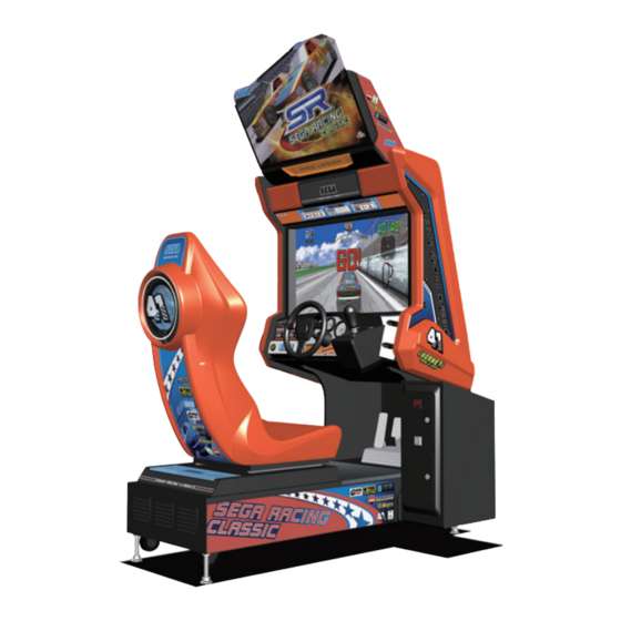
PART DESCRIPTIONS PART DESCRIPTIONS BILLBOARD STEERING WHEEL SHIFT LEVER LCD MONITOR COIN CHUTE DOOR SEAT CASHBOX DOOR ACCELERATOR & BRAKE UPPER DOOR LOWER DOOR AC UNIT Cabinet's Dimensions before Installation ITEMS Width Depth Height CABINET 1,015 mm (40.0 in) 1,510 mm (59.4 in) - 1,620 mm (63.8 in) 1,965 mm (77.4 in) -
Page 21: Accessories
ACCESSORIES ACCESSORIES Confirm that the accessories listed in the table below are present when setting up the product. Accessories marked Spare in the note column are consumable items but included as spares. Parts not labeled with part numbers are as yet unregistered or cannot be registered. Be sure to handle all parts with care, as some parts are not available for purchase separately. - Page 22 ACCESSORIES Part name/Part no. Diagram/Use etc. Quantity DC POWER SUPPLY WIRE 600-8026-200 For software installation VOLUME 220-5753 Spare MICROSWITCH 509-5636 Spare LAMP, 6.3 V, 1 W 390-5445-01 Spare DVD SOFTWARE KIT 610-0816-0009 When you order the DVD-ROM disc only, specify the part number DVR-0009 (RGW DVDROM SRC).
- Page 23 ACCESSORIES The DVD DRIVE is sold separately. If software installation becomes necessary, contact the point-of-purchase for this product. You can also order the parts using the kit numbers below. <XKT-1515-01: DVD DRIVE KIT FOR LBG ENG> Part name/Part no. Diagram/Use etc. Quantity DVD DRIVE SERVICE MANUAL 420-6923-01...
-
Page 24: Assembly And Installation
ASSEMBLY AND INSTALLATION ASSEMBLY AND INSTALLATION ● Perform assembly work by following the procedure herein stated. Failure to comply with the instructions can cause electric shock. ● Perform assembling as per this manual. Since this is a complex machine, incorrect assembling can cause an electric shock, machine damage and/or improper functioning as per specified performance. ● Ensure that connectors are properly connected. Improper connections can cause electric shock. ● This work should be carried out by the site maintenance personnel or other qualified professionals. Work performed by non-technical personnel can cause a severe accident such as electric shock. Failing to comply with this instruction can cause a severe accident such as electric shock to the player during operation. If no one with proper technological expertise is available, request service from the office indicated in this document or the point-of-purchase so as to ensure safety. - Page 25 ASSEMBLY AND INSTALLATION ● When opening/closing, attaching/removing doors or lids, be careful that your hand or finger does not get caught in anything. ● Support and hold parts in place securely and fasten them with screws and/or bolts. Use two workers, one to support the part and another to fasten it in place. If a part is not supported securely, it might fall down, resulting in an accident. ● Wear appropriate work clothing so that work can be performed safely. Use gloves and safety shoes to prevent accidents or injuries.
-
Page 26: Attaching The Billboard
ASSEMBLY AND INSTALLATION 6-1 ATTACHING THE BILLBOARD Attach the billboard (acrylic board) to the ASSY billboard. Insert it diagonally forward from above. Affix the billboard with 2 truss screws. TRUSS SCREW (2), black M3 x 6... -
Page 27: Securing In Place
ASSEMBLY AND INSTALLATION 6-2 SECURING IN PLACE ● Make sure that all the adjusters are resting on the floor. The cabinet may move and cause an accident if the adjusters are not laid out properly. ● Be sure to provide sufficient space for customers to pass and for ventilation as specified in this manual. If the cabinet is installed in a space that is narrower than specified, ventilation will be reduced and dust will accumulate quicker, and may cause overheating or fire. This product has 4 casters and adjusters each. ADJUSTER CASTER ADJUSTER Up to 4 cabinets can be connected for network play. See Chapter 19 for details on installing multiple machines. Move the product to the installation site. - Page 28 ASSEMBLY AND INSTALLATION Views are reduced to 1/100. Use them for reference in installation site layout. VENTILATION PORT SPACE: 0.2 m (7.9 in) 0.15 m (5.9 in) 0.7 m (27.6 in) or more Provide sufficient space for ventilation on the side with the vent. Leave at least 0.7 m (27.6 in) on the side that customers will pass by.
-
Page 29: Connecting The Power Cable And Earth
ASSEMBLY AND INSTALLATION 6-3 CONNECTING THE POWER CABLE AND EARTH ● Use the power supply equipped with an earth leakage breaker. Use of power supply without such a breaker could result in fire if there is a current leakage. ● Have available a securely grounded indoor earth terminal. Without proper grounding, customers could be electrocuted and product operations might not always be stable. ● Do not expose the power cable or earth wire. If these are exposed, customers could stumble over them, for instance, and easily damage them. Additionally, if these lines are damaged, there could be a risk of electrical shock or short circuit. Set these lines at locations where they will not interfere with customer traffic, or attach covers to them. - Page 30 ASSEMBLY AND INSTALLATION Connect one end of the earth wire to the AC earth terminal, and the other end to the indoor earth terminal. The accessory power cable contains earth wire. Connect power cable to AC unit inlet, and then insert power plug into “power outlet with earth terminal.”...
-
Page 31: Assembling Check
ASSEMBLY AND INSTALLATION 6-4 ASSEMBLING CHECK Initialization Operation Turn on the main power switch on the AC unit. Initialization will begin after the fluorescent lamp on the billboard lights up and the RINGWIDE startup screen displays on the monitor. The steering wheel will rotate left and right, then return to the middle. Once the initialization is complete for RINGWIDE and the internal system, the advertising (standby) screen will display on the monitor. - Page 32 ASSEMBLY AND INSTALLATION (1) MONITOR TEST In the SYSTEM TEST MODE menu, selecting MONITOR TEST allows the screen (on which the monitor is tested) to be displayed. Although the monitor adjustments have been made at the time of shipment from the factory, make needed by watching the TEST MODE screen.
-
Page 33: Precautions When Moving The Machine
PRECAUTIONS WHEN MOVING THE MACHINE PRECAUTIONS WHEN MOVING THE MACHINE ● Always disconnect the power cable before moving the product. If it is moved with the power cable connected, the cable could be damaged, causing fire or electric shock. ● To move the unit over the floor, pull in the adjustors and have the casters contact the floor. While moving the unit, be careful that the casters do not roll over the power cable or the earth wire. If cable or wire is damaged, there could be electrical shocks and/or short circuits. ● Do not push the cabinet from the left/right when attempting to move the cabinet. Pushing from the sides may cause the unit to tip and result in injury and damage to parts. - Page 34 PRECAUTIONS WHEN MOVING THE MACHINE Ground the casters. Do not push the cabinet from the left/right direction. Do not push on the slanted portion.
-
Page 35: Playing The Game
PLAYING THE GAME PLAYING THE GAME 8-1 GAME OUTLINE Speeds in excess of 300 km/h (186 mph)! Exhilarating head-to-head racing! The roar of powerful V8 engines and fiery exhaust! Experience the high-octane thrills of stock car racing on a world stage! This game is equipped with a network function, enabling up to 4 players to play simultaneously when the cabinets are connected. -
Page 36: Game Screens
PLAYING THE GAME 8-2 GAME SCREENS Tachometer & Speedometer Position Time limit Number of laps Surroundings Lap Time Rival car 8-3 GAME RULES The point of the game is to drive as fast as possible and take 1st place in the race. The time limit will begin running down as soon as the game starts. -
Page 37: How To Play
PLAYING THE GAME 8-4 HOW TO PLAY Start the game Insert coins. The game will start automatically when you have met the required amount of credits. Wait for opponents When multiple cabinets are connected and network play is enabled, cabinets without players will accept new players. - Page 38 PLAYING THE GAME Playing the game If the Beginner Course is selected, the cars will already be moving when the game starts (rolling start). NOTE: If you selected the 4-speed manual transmission, you should start out in 4th gear. On the Advanced and Expert courses, the cars will be sitting still when the game starts. BEGINNER COURSE ADVANCED COURSE/EXPERT COURSE Name entry...
-
Page 39: Hints For Playing The Game
PLAYING THE GAME 8-5 HINTS FOR PLAYING THE GAME Drift When turning sharp curves, drifting allows you to run the shortest path with minimal slowdown. The key to playing the game better is to drift skillfully using the brake and steering wheel. Drift Pit Stop You can keep your car in good condition by entering the pit on the course. -
Page 40: Explanation Of Test And Data Display
EXPLANATION OF TEST AND DATA DISPLAY EXPLANATION OF TEST AND DATA DISPLAY Do not touch any parts that are not specified in these directions. Touching unspecified locations may lead to electric shock or cause short circuits. When exit the TEST MODE, the steering wheel moves automatically for initializing. Do not touch the steering wheel until the steering wheel has completely stopped moving to prevent accidents or injuries. If you touch the steering wheel before initialization is finished, there could be problems with operability. ● Adjust the sound to the optimum volume, taking into consideration the environmental requirements of the installation location. -
Page 41: Switch Unit
EXPLANATION OF TEST AND DATA DISPLAY 9-1 SWITCH UNIT Be careful that a finger or hand does not get caught when opening/closing the door. ● Adjust the sound to the optimum volume, taking into consideration the environmental requirements of the installation location. ● Removing the coin meter circuitry renders the game inoperable. Unlock and open the coin chute door. Inside is a switch unit. Switch Unit TEST Button Establishes TEST MODE. Becomes the button to confirm selections in TEST (TEST) MODE. -
Page 42: System Test Mode
EXPLANATION OF TEST AND DATA DISPLAY 9-2 SYSTEM TEST MODE ● The details of changes to TEST MODE settings are saved when you exit from TEST MODE by selecting EXIT from the SYSTEM TEST MODE menu. Be careful because if the power is turned off before that point, changes to the settings will be lost. ● Use with the specified settings. If settings other than those specified are used, inappropriate operations or malfunction may occur. -
Page 43: Game Test Mode
● Use with the specified settings. If settings other than those specified are used, inappropriate operations or malfunction may occur. Select GAME TEST MODE from the SYSTEM TEST MENU screen to display the GAME TEST MODE screen as follows. SEGA RACING CLASSIC GAME TEST MODE BOOKKEEPING INPUT TEST OUTPUT TEST DRIVE BD TEST... - Page 44 EXPLANATION OF TEST AND DATA DISPLAY Use the SERVICE Button to move the cursor to the desired test item. Press the TEST Button to select the test item. The various input devices can be used to perform operations in TEST MODE. SHIFT LEVER cursor UP/DOWN START button...
-
Page 45: Bookkeeping
EXPLANATION OF TEST AND DATA DISPLAY 9-3-2 BOOKKEEPING Each game record can be viewed. On the GAME TEST MODE screen, select BOOKKEEPING and press the TEST Button. The BOOKKEEPING 1/2 screen appears. BOOKKEEPING 1/2 CREDIT COIN 1 COIN 2 COIN 3 COIN 4 TOTAL COINS COIN CREDITS... - Page 46 EXPLANATION OF TEST AND DATA DISPLAY Press the TEST Button to move to the BOOKKEEPING 2/2 screen. BOOKKEEPING 2/2 OPERATION NUMBER OF GAMES TOTAL TIME **:**:** TOTAL PLAY TIME **:**:** AVERAGE PLAY TIME **:** LONGEST PLAY TIME **:** SHORTEST PLAY TIME **:** BEGINNER COURSE NUMBER OF GAMES...
-
Page 47: Input Test
EXPLANATION OF TEST AND DATA DISPLAY 9-3-3 INPUT TEST Select INPUT TEST to display the following screen and check the status of input devices. This test should be used periodically to check that each input device is functioning correctly. On the GAME TEST MODE screen, select INPUT TEST and press the TEST Button. The INPUT TEST screen appears. -
Page 48: Output Test
EXPLANATION OF TEST AND DATA DISPLAY 9-3-4 OUTPUT TEST This screen is for confirming the proper operation of each output device used by the game. Periodically use this screen to check the status of each output device. On the GAME TEST MODE screen, select OUTPUT TEST and press the TEST Button. The OUTPUT TEST screen appears. -
Page 49: Drive Bd Test
EXPLANATION OF TEST AND DATA DISPLAY 9-3-5 DRIVE BD TEST This screen is for checking the steering wheel's force feedback. Periodically use this screen to check that the steering wheel's force feedback is operating normally. On the GAME TEST MODE screen, select DRIVE BD TEST and press the TEST Button. The DRIVE BD TEST screen appears. - Page 50 EXPLANATION OF TEST AND DATA DISPLAY <DIP SW Settings Chart> The DIP SW settings on the drive board can be used to set the steering wheel resistance, select whether to perform the power on check, etc. Leave DIP SW 5-8 OFF. The drive board is mounted on the sub electric unit (ASSY ELEC).
-
Page 51: Game Assignments
EXPLANATION OF TEST AND DATA DISPLAY 9-3-6 GAME ASSIGNMENTS All settings such as level of game difficulty or mode of the game are adjusted. On the GAME TEST MODE screen, select GAME ASSIGNMENTS and press the TEST Button. The GAME ASSIGNMENTS screen appears. GAME ASSIGNMENTS START UP MODE SINGLE... - Page 52 EXPLANATION OF TEST AND DATA DISPLAY Use the SERVICE Button to move the cursor to the desired test item. Press the TEST Button to select the test item. When all setting adjustments are completed, select EXIT and press the TEST Button. The GAME TEST MODE screen reappears.
-
Page 53: Game System Information
View information about the game. On the GAME TEST MODE screen, select GAME SYSTEM INFORMATION and press the TEST Button. The GAME SYSTEM INFORMATION screen appears. GAME SYSTEM INFORMATION TITLE: SEGA RACING CLASSIC DATE: ****-**-** T **:**:**:** **:** VERSION: *.**.**... -
Page 54: Backup Data Clear
EXPLANATION OF TEST AND DATA DISPLAY 9-3-8 BACKUP DATA CLEAR Delete all game records (game scores and GAME TEST MODE BOOKEEPING data). On the GAME TEST MODE screen, select BACKUP DATA CLEAR and press the TEST Button. The BACKUP DATA CLEAR screen appears. BACKUP DATA CLEAR YES (CLEAR) ->NO (CANCEL) -
Page 55: Lcd Monitor
LCD MONITOR LCD MONITOR Do not make careless adjustments. Making the wrong adjustment to the settings could lead to problems that are not easily fixed. If you are unable to make the adjustments you desire, contact the office listed in this manual or the point-of- purchase for this product. 10-1 CLEANING THE LCD MONITOR SCREEN ● The LCD monitor screen is easily scratched, so be careful when cleaning it. - Do not contact the antistatic sheet on the screen surface, or rub it, with a hard implement (pointed bar or pen, etc.). -
Page 56: Adjusting The Lcd Monitor
LCD MONITOR 10-2 ADJUSTING THE LCD MONITOR ● Avoid any unnecessary adjustment. Adjusting the monitor may lead to electric shock or cause short circuits. If a mistake is made while performing adjustments, the game may stop operating. ● Be careful not to damage the wires. Damaged wires may cause electric shock or short circuit or present a risk of fire. ● Do not touch any parts that are not specified in these directions. Touching unspecified locations may lead to electric shock or cause short circuits. ● Be sure to perform appropriate adjustment of the monitor (LCD). For operation of this machine, do not leave monitor's flickering or deviation as is. Failure to observe this can have a bad influence upon the players' or the customers' physical conditions. ● When attaching or removing doors, be careful that your hand or finger does not get caught in anything. - Page 57 LCD MONITOR How to Access the Adjustment Board Turn off the power switch of the cabinet. Remove the 2 truss screws and take off the upper door on the back side of the cabinet. TRUSS SCREW (2), black M4 x 30, w/flat & spring washers, large flat washer used M4 x 30, w/flat &...
- Page 58 LCD MONITOR Description of Functions ↓ AUTO MENU MODE + − Power LED Green Light is with the signal; Red Light is signal out of range or no signal. ↓MODE Enter selected item/move down. “+” Press the button to adjust the increasing value of selected OSD control item. “-”...
- Page 59 LCD MONITOR OSD Operation Appearance Press MENU and the screen will appear the following OSD Menu. Display Adjustment Language Selection Input Signal Selection Color Menu Adjustment Selection H . Pos i t i o n V . Pos i t i o n H ....
- Page 60 Set Display Mode. W mode Enter 4:3, 5:4 or 16:9, 16:10 the display image will stretch to full screen. (Used for Sega Racing Classic.) N1 Mode Enter 4:3, 5:4, or 16:10, the image will display in the middle and settle the vertical rate, but in order to adjust only horizon display image to 1:1.
- Page 61 LCD MONITOR Input Signal Selection Analog Input Analog signal (Used for Sega Racing Classic.) Digital Input Digital signal NOTE: If it can’t find the input signal or input signal is cut off, the display will start stand-by mode in 5 seconds.
-
Page 62: Control Panel (Steering Wheel Mechanism)
CONTROL PANEL (STEERING WHEEL MECHANISM) CONTROL PANEL (STEERING WHEEL MECHANISM) ● When working with the product, be sure to turn the power off. Working with the power on may cause an electric shock or short circuit. However, the unit must be switched on when using TEST MODE. Do not touch any part of the unit except those areas indicated. ● Be careful not to damage the wires. Damaged wires may cause electric shock or short circuit or present a risk of fire. ● This work should be performed by the site maintenance individual or other skilled professional. Performing work with non-technical personnel can cause electric shock. -
Page 63: Volume Adjustment
CONTROL PANEL (STEERING WHEEL MECHANISM) 11-1 VOLUME ADJUSTMENT Check the volume value of the steering wheel once a month and adjust it if necessary. At the same time, check the handling of the steering wheel. The steering wheel has two volumes. The upper side is for the drive board, and the lower side is for the game board. Check the volume value of the drive board volume on the DRIVE BD TEST screen, and check the volume value of the game board volume on the INPUT TEST screen. -
Page 64: Volume Replacement
CONTROL PANEL (STEERING WHEEL MECHANISM) 11-2 VOLUME REPLACEMENT Turn the power off. Remove the 2 screws and take off the upper door on the back of the cabinet. (See 10-2.) Remove the wire connector coming out from the volume. The wire for the upper drive board volume has an “UP”... -
Page 65: Greasing
CONTROL PANEL (STEERING WHEEL MECHANISM) 11-3 GREASING ● Be sure to use the designated grease. Using undesignated grease can cause parts damage. ● Do not apply grease to locations other than as specified. Doing so may create a risk of operational problems and deterioration of parts. ● The designated periods for greasing serve only as a guide. Whenever there are squeaks or other anomalies, apply grease at designated locations. Grease the parts listed below once every 3 months. Use GREASE MATE (PART No. 090-0066) as spray grease. Remove the upper door on the back of the cabinet, and apply grease to the teeth of the gears that turn the volume axis. -
Page 66: Shift Lever
SHIFT LEVER SHIFT LEVER ● When working with the product, be sure to turn the power off. Working with the power on may cause an electric shock or short circuit. However, the unit must be switched on when using TEST MODE. Do not touch any part of the unit except those areas indicated. ● Be careful not to damage the wires. Damaged wires may cause electric shock or short circuit or present a risk of fire. ● This work should be performed by the site maintenance individual or other skilled professional. Performing work with non-technical personnel can cause electric shock. ● Do not touch the steering wheel when switching on the unit. The steering wheel undergoes automatic initialization after the unit is switched on. -
Page 67: Replacing Microswitches
SHIFT LEVER 12-2 REPLACING MICROSWITCHES Turn off the power switch of the cabinet. Remove the 4 tamperproof screws, and remove the shift cover. SHIFT COVER TAMPERPROOF SCREW (4), black M4 x 12 Remove the 2 screws and take off the upper door on the back of the cabinet. (See 10-2.) Disconnect the connector farthest to the left when facing the inside of the upper door. - Page 68 SHIFT LEVER Remove the 4 special bolts, and remove the shift lever. Be sure not to damage the wiring. SPECIAL BOLT (4) DYN-1224X Each microswitch is fastened in place with 2 screws. Remove each set of screws and replace the microswitches.
-
Page 69: Accelerator & Brake
ACCELERATOR & BRAKE ACCELERATOR & BRAKE ● When working with the product, be sure to turn the power off. Working with the power on may cause an electric shock or short circuit. However, the unit must be switched on when using TEST MODE. Do not touch any part of the unit except those areas indicated. ● Be careful not to damage the wires. Damaged wires may cause electric shock or short circuit or present a risk of fire. ● This work should be performed by the site maintenance individual or other skilled professional. Performing work with non-technical personnel can cause electric shock. -
Page 70: Volume Adjustment And Replacement
ACCELERATOR & BRAKE 13-1 VOLUME ADJUSTMENT AND REPLACEMENT The appropriate value for acceleration volume is under 30H when released and over C0H when stepped on. The appropriate value for brake volume is under 35H when released and over D0H when stepped on. Check Volume values in the TEST mode. - Page 71 ACCELERATOR & BRAKE Replacement Method Turn off the power switch of the cabinet. Remove 2 screws, and remove the potentiocover. TRUSS SCREW (2), chrome M4 x 8 POTENTIOCOVER POTENTIOBASE Undo the connector of the volume to be replaced. Remove the screw that fastens the potentiobase. (See the figure above.) With the volume still attached, remove the potentiobase.
-
Page 72: Greasing
ACCELERATOR & BRAKE 13-2 GREASING Be sure to use the designated grease. Using undesignated grease can cause parts damage. Grease the spring and gear alignment area once every 3 months. Use GREASE MATE (PART No. 090-0066) as spray grease. Apply grease. -
Page 73: Coin Selector
COIN SELECTOR COIN SELECTOR 14-1 COIN INSERTION TEST Once every month, when performing the coin switch test, simultaneously check the following: □ Does the coin meter count satisfactorily? □ Does the coin drop into the cashbox correctly? □ Is the coin rejected when inserted while keeping the reject button pressed down? REJECT BUTTON COIN INSERT SLOT COIN RETURN SLOT... -
Page 74: Cleaning The Coin Selector
COIN SELECTOR 14-2 CLEANING THE COIN SELECTOR ● Remove and clean smears by using a soft cloth dipped in water or diluted chemical detergent and then squeezed dry. ● Never apply machine oil, etc. to the coin selector. ● After cleaning the coin selector, insert a regular coin in the normal working status and ensure that the selector correctly functions. The coin selector should be cleaned once every 3 months. When cleaning, follow the procedure below: Turn off the power switch of the cabinet. Unlock the coin chute door with the master key, and open it. -
Page 75: Handling The Coin Jam
COIN SELECTOR 14-3 HANDLING THE COIN JAM If the coin is not rejected when the REJECT button is pressed, open the coin chute door and open the selector gate. After removing the jammed coin, put a normal coin in and check to see that the selector correctly functions. -
Page 76: Ringwide (Game Board)
RINGWIDE (GAME BOARD) RINGWIDE (GAME BOARD) ● When working with the product, be sure to turn the power off. Working with the power on may cause an electric shock or short circuit. ● Have work pertaining to electric circuitry such as with the game board done by the site maintenance personnel or other qualified professionals. Otherwise there could be an electric shock or other serious accident. If no one with proper knowledge and skills is available, request work from the point of purchase or the office indicated in these instructions. ● Be careful not to damage the wires. Damaged wires may cause electric shock or short circuit or present a fire risk. - Page 77 RINGWIDE (GAME BOARD) ● Static electricity from your body may damage some electronics devices on the IC board. Before handling the IC board, touch a grounded metallic surface so that the static electricity can be discharged. ● For replacement or repair, pack the game board and send it without disassembling it. Order for servicing might not be accepted if any part of the game board has been removed. If any part is removed, a service fee will be charged even if the warranty period has not yet expired. ● For replacement or repair, remove the key chip from the game board and send for servicing.
-
Page 78: Cleaning The Game Board And Surrounding Parts
RINGWIDE (GAME BOARD) 15-1 CLEANING THE GAME BOARD AND SURROUNDING PARTS Clean the game board and surrounding parts once a year, or when an “Error 0090” or “Error 0091” appears. Clean the game board exhaust vent area and surrounding parts once a year with a vacuum cleaner. Turn off the power switch of the cabinet. Remove 1 truss screw each from left and right sides of Base Lid. Unlock the base with the master key. -
Page 79: Removing The Game Board
RINGWIDE (GAME BOARD) 15-2 REMOVING THE GAME BOARD Components, software and settings vary by game board. Return the game board to the cabinet it was removed from. Returning it to the wrong cabinet may lead to malfunctions or failure. Turn the power off. Lower the seat towards. -
Page 80: Composition Of Ringwide
RINGWIDE (GAME BOARD) 15-3 COMPOSITION OF RINGWIDE ● With the key chip inserted into it, this board serves as a special-purpose game board for the product. ● The DIP SW (dip switches) on the board must be set as specified below. If set incorrectly for this product, an error will be displayed and the game will not run. ● Do not connect the DVI terminal. Accidentally connecting it could lead to damage or malfunction. ASSY CASE WDE W 1GB EXP (847-0001D-02): Others ASSY CASE WDE W 1GB USA (847-0001D-01): USA DIP SW RINGWIDE External View DIP SW Setting... -
Page 81: Fluorescent Light/Other Lamps Replacement
FLUORESCENT LIGHT/OTHER LAMPS REPLACEMENT FLUORESCENT LIGHT/OTHER LAMPS REPLACEMENT ● When working with the product, be sure to turn the power off. Working with the power on may cause an electric shock or short circuit. ● You may get burned by a hot fluorescent lamp or other lamps. Pay full attention to the lamps when performing the work. ● Use lamps of the specified ratings. Using lamps with different ratings may cause fires or damage. ● There is the danger of short circuits or smoke generation due to deterioration of insulation in lighting fixtures resulting from age deterioration. Check for anomalies such as the following: Does it smell like something is burning? Is there socket discoloration? Are any lamps being replaced frequently? Do lamps not go on properly? ● Be careful when handling the plastic parts. Failure to observe this may cause... -
Page 82: Billboard Fluorescent Light
FLUORESCENT LIGHT/OTHER LAMPS REPLACEMENT 16-1 BILLBOARD FLUORESCENT LIGHT Turn the power off. Fasten the billboard (acrylic board) in place with 2 truss screws. TRUSS SCREW (2), black M3 x 6 Remove the billboard so that it comes out diagonally upward. Remove the 3 truss screws, take off the transparent acrylic backboard, and replace the fluorescent lights. -
Page 83: Start Button Lamp, View Change Button Lamp
FLUORESCENT LIGHT/OTHER LAMPS REPLACEMENT 16-2 START BUTTON LAMP, VIEW CHANGE BUTTON LAMP Turn the power off. Remove the 4 tamperproof screws. TAMPERPROOF SCREW (4), black M4 x 16 Remove the switch plate. The switch plate contains wiring connections on backside. Disconnect the connector, taking care not to damage the wiring. - Page 84 FLUORESCENT LIGHT/OTHER LAMPS REPLACEMENT There is a metal fitting at the base of the buttons on the button plate backside. Rotate this metal fitting to unlock it, then remove the printed circuit board from the button plate. METAL FITTING BUTTON PLATE PRINTED CIRCUIT BOARD Press and turn the lamp counter-clockwise to remove it.
-
Page 85: Periodic Inspection
PERIODIC INSPECTION PERIODIC INSPECTION ● The site maintenance personnel or other qualified professionals should perform work that involves touching the inside of this product. Otherwise, it could lead to electrocution or other serious accidents. ● Be sure to check once a year to see whether power cables are damaged, the plug is securely inserted, dust has accumulated between the socket outlet and the power plug, etc. Using the product with accumulated dust can cause fire and electric shock. ● Periodically, around once a year, get in touch with the office herein stated or the distributor, etc. where the product was purchased from, regarding internal cleaning. - Page 86 PERIODIC INSPECTION PERIODIC INSPECTION TABLE PERIOD ITEMS DESCRIPTION REFERENCE As appropriate ELECTRONIC/ELECTRICAL Inspection As above PARTS CABINET SURFACES Cleaning Next page Daily CABINET Confirm that adjusters contact floor CABINET JOINTS Inspection DOOR, CONTROL PANEL, SEAT Weekly LCD MONITOR Monitor screen cleaning 10-1 Monthly CONTROL PANEL...
- Page 87 Move the seat to the rearmost position and apply spray greasing to the portion shown at the right once every 3 months by using NOK KLUBER L60 or GREASE MATE SEGA PART No. 090-0066. After greasing, move the seat a few times forward and backward so as to allow the grease to be applied all over uniformly.
-
Page 88: Troubleshooting
TROUBLESHOOTING TROUBLESHOOTING 18-1 PROBLEMS OTHER THAN ERROR MESSAGES ● This work should be carried out by the site maintenance personnel or other qualified professionals. Work performed by non-technical personnel can cause a severe accident such as electric shock. ● When working with the product, be sure to turn the power off. Working with the power on may cause an electric shock or short circuit. ● Be careful not to damage the wires. Damaged wires may cause electric shock or short circuit or present a risk of fire. ● Once the reason that the circuit protector activated has been removed, restore the circuit protector to its original condition. If the product is used while the reason for activation has not yet been removed, heat and/or fire could be generated. - Page 89 TROUBLESHOOTING TROUBLESHOOTING TABLE PROBLEMS CAUSE COUNTERMEASURES With main switch ON, no Power is not supplied. Securely insert the power plug into the plug activation. socket. Power supply/voltage is not Make sure that power supply/voltage is correct. correct. The circuit protector functioned After eliminating the cause of overload, due to the momentary overload.
- Page 90 TROUBLESHOOTING PROBLEMS CAUSE COUNTERMEASURES No response from Steering Failure of power-on checking Reconnect the power and complete a power-on (Servomotor). procedure. checking procedure. (See Section 6-4.) Faulty connector connections. Check the connections for the connectors between the game board and servodriver and between the servodriver and the servomotor.
-
Page 91: Error Messages
TROUBLESHOOTING 18-2 ERROR MESSAGES When this product detects an abnormality, the following messages will be displayed. Note the information about the error when managing the problem. For error messages displayed at the RINGWIDE logo screen, consult the “RINGWIDE Service Manual.” MESSAGE GAME ASSIGNMENTS ERROR Duplicative CAR NUMBER... -
Page 92: Software Installation
TROUBLESHOOTING 18-3 SOFTWARE INSTALLATION ● Looking directly at the laser of the DVD DRIVE may cause eye injuries. Do not look inside the DVD DRIVE. ● When connecting the connectors, be sure to attach them correctly. There is only one correct way in which they must be connected. Attempting to connect them incorrectly may cause damage to the pins on the connectors, and cause electric shock, short circuit or fire. ● Static electricity from your body may damage some electronics devices on the IC board. - Page 93 TROUBLESHOOTING Recline the seat back. (See 15-1.) Loosen the 2 screws on one of the LAN cable lids on the left and right of the lower door that holds it in place. It does not matter which one. LAN CABLE LID SCREW (2), black M4 x 16, w/flat &...
- Page 94 TROUBLESHOOTING Connect the plug-side connector on the DC power supply wire used for installation to RINGWIDE, and connect the cap-side connector to the connector unplugged from RINGWIDE. CAP-SIDE CONNECTOR PLUG-SIDE CONNECTOR Remove the USB port 1 cap of RINGWIDE. Connect the connector on the USB wire used for installation to USB port 1. The connectors on either side of the USB wire are not the same.
- Page 95 TROUBLESHOOTING Put the connectors on the opposite ends of the DC power supply wire and USB wire through the space opened by sliding the LAN cable lid. Connect 2 connectors passed through the hole to DVD DRIVE. Turn on the power switch of the cabinet. RINGWIDE start-up screen is displayed on the monitor screen.
- Page 96 TROUBLESHOOTING Press the DVD DRIVE switch. The DVD DRIVE tray comes out. Set the DVD from the DVD software kit into the tray. Always have the DVD label side facing upward. Press the DVD DRIVE switch and the tray returns to its original position. Software installs automatically from the DVD.
-
Page 97: Network Play
NETWORK PLAY NETWORK PLAY For this game, up to 4 machines can be connected to allow up to 4 players to play simultaneously. In this instance, connecting the network cable and setting for the network play are required. 19-1 INSTALLATION PRECAUTIONS ● The work described below should be carried out by the site maintenance personnel or other qualified professional. Work carried out by personnel without the necessary skill or technology can cause accident. - Page 98 NETWORK PLAY Since 2 or more machines are to be linked, sufficient power corresponding to the number of machines used need to be supplied. Note that as a standard, the per machine capacity should be 15 A for the 100 V - 120 V area, and 7 A for the 220 V - 240 V area.
-
Page 99: How To Connect 2 Cabinets
NETWORK PLAY 19-2 HOW TO CONNECT 2 CABINETS The following instructions are for connecting 2 cabinets for network play. Prepare one of the 5 m LAN cables supplied with the 2 cabinets. Move the 2 cabinets and line them up with the specified distance between them. Recline the seat back. (See 15-1.) The following work is the same for both cabinets. Remove 4 truss screws, and remove the base lid F. - Page 100 NETWORK PLAY Loosen the 2 screws on one of the LAN cable lids on the left and right of the lower door that hold it in place. It does not matter which one, but you should try to use the one that will keep the length of the LAN cable coming out from the cabinet to a minimum.
- Page 101 NETWORK PLAY Use the cord clamp fastening the wires in place inside the cabinet to fasten the 5 m LAN cable in place. DRIVE BOARD Affix the LAN cable. Attach base lid F and put the seat back up. Wire the power cable and LAN cable and attach the protective cover. Turn the cabinets on and configure each of them for network play in TEST MODE.
-
Page 102: How To Connect 3 Or 4 Cabinets
NETWORK PLAY 19-3 HOW TO CONNECT 3 OR 4 CABINETS To set up 3 or 4 cabinets for network play you will need the separate HUB KIT (XKT-1848-01). The HUB KIT includes the parts listed below. Before assembling it, make sure you have all the parts. The part names below are the ones used in the assembly procedure. - Page 103 NETWORK PLAY Remove the 2 screws, and take off the lower door. SCREW (2), black M4 x 30, w/flat & spring washers, large flat washer used Slide the LAN cable lid on the lower door towards the center and fasten it in place. (See 19-2.) Connect the 5 m LAN cable to RINGWIDE inside the cabinet.
- Page 104 NETWORK PLAY Mount the ASSY hub using the 4 screws included with the kit. Be careful not to pinch the wires. SCREW (4) M4 x 16, w/flat & spring washers Connect the connector on the temporarily fastened 5 m LAN cable to a LAN port on the ASSY hub.
- Page 105 NETWORK PLAY Affix the lower door with the 2 screws. Pass through the LAN cable. Attach the lower doors to the other cabinets in the same way. Wire the power cable and LAN cable and attach the protective cover. Turn the cabinets on and configure each of them for network play in TEST MODE. (See 9-3-6)
-
Page 106: Network Play Precautions
NETWORK PLAY 19-4 NETWORK PLAY PRECAUTIONS ● If any of the cabinets connected for network play enters TEST MODE, the other cabinets will: <During the advertisements (standby)> Go to the screen that follows startup and will be in standby mode until the other cabinet recovers and re-establishes a connection to the network. <During game play> Regular game play will continue until the game is over. After the game ends, it will do the same thing as if it were on the advertisements screen. ● Even when cabinets are connected for network play, each seat, each game may be given different cost settings. Incorrect cost settings may cause budget balancing problems. The operation of a cabinet when connected to other cabinets for network play is different than that of a stand-alone cabinet. -
Page 107: Design-Related Parts
DESIGN-RELATED PARTS DESIGN-RELATED PARTS For the warning display stickers, refer to Chapter 1. LIGHT BOX STICKER L BILLBOARD SRC-0509 SRC-0507 PLAY INSTR SH SRC ENG LEADER LAMP BOARD SRC-0002-01 SRC-0532 STICKER CENTER PANEL SRC-1354 STICKER METER PANEL STICKER SEAT UPPER SRC-2001-D SRC-1651-B STICKER SIDE PANEL L... - Page 108 PARTS LIST PARTS LIST Plan Formation Chart (2) SRC-0300 (1) SRC-0000 (3) SRC-0320 TOP ASSY SRC ASSY COIN CHUTE TOWER SW UNIT (4) SRC-0500 (5) SRC-0530 ASSY BILLBOARD ASSY LEADER LAMP (6) SRC-1000 (7) SRC-1200 ASSY COCKPIT ASSY MONITOR CABI (20) SRC-1500 ASSY MAIN BASE (34) SRC-1020...
- Page 109 PARTS LIST (8) SRC-1250 ASSY SUB MONTOR CABI (9) SRC-1270 FAN UNIT (10) SRC-1280 ASSY LCD MONITOR (11) SRC-1290 ASSY SPEAKER (12) SRC-1300 ASSY MONITOR MASK (13) SRC-1350 ASSY SPEAKER PANEL (14) SRC-2000 (15) SRC-2500 ASSY HANDLE MECHA ASSY CONTROL PANEL SRC-2500-01 SRC-2000-01 ASSY CONTROL PANEL UL...
- Page 110 PARTS LIST (1) SRC-0000 (D-1/2) TOP ASSY SRC...
- Page 111 PARTS LIST (1) SRC-0000 (D-2/2) TOP ASSY SRC ITEM NO. PART NO. DESCRIPTION NOTE SRC-0300 ASSY COIN CHUTE TOWER SRC-0500 ASSY BILLBOARD SRC-1000 ASSY COCKPIT SRC-0001 WIRE COVER DYN-0011 DENOMI PLATE W/O ORIGINAL SRC-0002-01 PLAY INSTR SH SRC ENG SRC-0003-01 SUB INSTR SH SRC ENG 421-11416 STICKER CAUTION FORK...
- Page 112 PARTS LIST (2) SRC-0300 (D-1/2) ASSY COIN CHUTE TOWER...
- Page 113 PARTS LIST (2) SRC-0300 (D-2/2) ASSY COIN CHUTE TOWER ITEM NO. PART NO. DESCRIPTION NOTE SRC-0301X COIN CHUTE TOWER SRC-0320 SW UNIT TOF-0302X METER BRKT APC-0302X METER HOLE LID DP-1167 TNG LKG 105-5592 CHUTE PLATE SINGLE 105-5592-CN CHUTE PLATE SINGLE 421-7501-02 STICKER 6.3V 0.15A 421-6591-01...
- Page 114 PARTS LIST (3) SRC-0320 SW UNIT ITEM NO. PART NO. DESCRIPTION NOTE SRC-0321 SW BRKT 421-12136 STICKER SW PANEL LCA 838-14548-01 SW & C VOL BD 000-P00308-W M SCR PH W/FS M3x8...
- Page 115 PARTS LIST (4) SRC-0500 (D-1/2) ASSY BILLBOARD...
- Page 116 PARTS LIST (4) SRC-0500 (D-2/2) ASSY BILLBOARD ITEM NO. PART NO. DESCRIPTION NOTE SRC-0530 ASSY LEADER LAMP SRC-0501 BILLBOARD BOX SRC-0502X FL BRKT SRC-0503 BILLBOARD BRKT UNDER SRC-0504 BILLBOARD SIDE BRKT SRC-0505 BACK BOARD BRKT SRC-0506 BACK BOARD SRC-0507 BILLBOARD SRC-0508 BACK LID SRC-0509...
- Page 117 PARTS LIST (5) SRC-0530 ASSY LEADER LAMP ITEM NO. PART NO. DESCRIPTION NOTE SRC-0531X LEADER LAMP FRONT MASK SRC-0532 LEADER LAMP BOARD SRC-0533 LED BAR BRKT SRC-0534 LED CASE SRC-0535 STICKER MIRROR 838-14972-07 LED BD WHITE 3x7BLOCK 280-7881 CORD CLAMP SR10 CN 280-5185-5 SPACER TUBE L=5 FAS-000126...
- Page 118 PARTS LIST (6) SRC-1000 ASSY COCKPIT EARTH EARTH ITEM NO. PART NO. DESCRIPTION NOTE SRC-1200 ASSY MONITOR CABI SRC-1500 ASSY MAIN BASE SRC-1020 ASSY LOWER DOOR SRC-1001 MON CABI PLATE UPPER SRC-1002 MON CABI PLATE LOWER SRC-1003 UPPER DOOR 030-000830-S HEX BLT W/S M8x30 068-852216-0B FLT WSHR BLK 8.5-22x1.6...
- Page 119 PARTS LIST (7) SRC-1200 (D-1/2) ASSY MONITOR CABI...
- Page 120 PARTS LIST (7) SRC-1200 (D-2/2) ASSY MONITOR CABI ITEM NO. PART NO. DESCRIPTION NOTE SRC-1250 ASSY SUB MONITOR CABI SRC-1270 FAN UNIT SRC-1280 ASSY LCD MONITOR SRC-1290 ASSY SPEAKER SRC-1300 ASSY MONITOR MASK SRC-1350 ASSY SPEAKER PANEL SRC-2000 ASSY CONTROL PANEL SRC-2000-01 ASSY CONTROL PANEL UL SRC-1201X...
- Page 121 PARTS LIST (8) SRC-1250 ASSY SUB MONTOR CABI SECTION A-A ITEM NO. PART NO. DESCRIPTION NOTE SRC-1251X MONITOR CABINET SRC-1252 CONNECT BRKT L SRC-1253 CONNECT BRKT R SRC-1255 MONITOR SUPPORT SRC-1256 MONITOR SUPPORT PLATE SRC-1257 CONNECT BRKT OUTER L SRC-1258 CONNECT BRKT OUTER R SRC-1259 NUT PLATE L...
- Page 122 PARTS LIST (9) SRC-1270 FAN UNIT ITEM NO. PART NO. DESCRIPTION NOTE 105-5636 FAN BRKT 260-0116 FAN AC115V A1123-HBT-GN 601-8543 FAN GUARD 000-P00312-W M SCR PH W/FS M3x12...
- Page 123 PARTS LIST (10) SRC-1280 ASSY LCD MONITOR ITEM NO. PART NO. DESCRIPTION NOTE SRC-1281 LCD BRKT 200-6163-92 ASSY LCD DSPL 32TYPE Y 000-P00416-W M SCR PH W/FS M4x16...
- Page 124 PARTS LIST (11) SRC-1290 ASSY SPEAKER Terminal side ITEM NO. PART NO. DESCRIPTION NOTE SRC-1291 WOODEN SPEAKER BOARD 130-5284 SPEAKER 8OHM F01612HO NJS FAS-110030 TAP SCR TH #1 BLK 4x12 SRC-60005 WH SPEAKER PANEL...
- Page 125 PARTS LIST (12) SRC-1300 ASSY MONITOR MASK ITEM NO. PART NO. DESCRIPTION NOTE SRC-1301X MONITOR MASK 275-0146 PROTECTIVE GLASS LCD 32V SRC-1302 GLASS HOLDER UL SRC-1303 GLASS HOLDER LR SRC-1304 GLASS CUSHION UL SRC-1305 GLASS CUSHION LR SRC-1306 MASK SPACER UL SRC-1307 MASK SPACER LR 050-F00400...
- Page 126 PARTS LIST (13) SRC-1350 ASSY SPEAKER PANEL ITEM NO. PART NO. DESCRIPTION NOTE SRC-1351X SPEAKER PANEL SRC-1352 CENTER PANEL SRC-1353 SPEAKER COVER SRC-1354 STICKER CENTER PANEL 000-P00408-W M SCR PH W/FS M4x8 FAS-290042 HEX SKT LH CAP SCR STN M4x12...
- Page 127 PARTS LIST (14) SRC-2000 (D-1/2) ASSY CONTROL PANEL...
- Page 128 PARTS LIST (14) SRC-2000 (D-2/2) ASSY CONTROL PANEL ITEM NO. PART NO. DESCRIPTION NOTE SRC-2500 ASSY HANDLE MECHA SPG-2150-01 ASSY 4 SPEED SHIFTER DYN-1290 ASSY VIRTUAL BUTTON TWIN SRC-2001 CONTROL PANEL COVER SRC-2002X CONTROL PANEL BRKT DYN-1222 SHIFT COVER A DYN-1223X SHIFT COVER B DYN-1224X...
- Page 129 PARTS LIST (14) SRC-2000-01 (D-1/2) ASSY CONTROL PANEL UL EARTH...
- Page 130 PARTS LIST (14) SRC-2000-01 (D-2/2) ASSY CONTROL PANEL UL ITEM NO. PART NO. DESCRIPTION NOTE SRC-2500-01 ASSY HANDLE MECHA SPG-2150-01 ASSY 4 SPEED SHIFTER DYN-1290 ASSY VIRTUAL BUTTON TWIN SRC-2001 CONTROL PANEL COVER SRC-2002X CONTROL PANEL BRKT DYN-1222 SHIFT COVER A DYN-1223X SHIFT COVER B DYN-1224X...
- Page 131 PARTS LIST (15) SRC-2500 (D-1/3) ASSY HANDLE MECHA...
- Page 132 PARTS LIST (15) SRC-2500 (D-2/3) ASSY HANDLE MECHA ITEM NO. PART NO. DESCRIPTION NOTE SRC-2501 HANDLE BASE DYN-1252X BASE LID SRC-2502 HANDLE SHAFT SRC-2504 DRIVE PULLEY DYN-1255 HANDLE PULLEY DYN-1256 CLUTCH PULLEY A DYN-1257 CLUTCH PULLEY B DYN-1258X MOTOR BRACKET DYN-1259X CLUTCH BRACKET DYN-1260X...
- Page 133 PARTS LIST (15) SRC-2500 (D-3/3) ASSY HANDLE MECHA ITEM NO. PART NO. DESCRIPTION NOTE 020-000410-HZ HEX SKT CAP SCR BLK OZ M4x10 020-000512-HZ HEX SKT CAP SCR BLK OZ M5x12 060-S00400 SPR WSHR M4 060-S00500 SPR WSHR M5 000-P00408-W M SCR PH W/FS M4x8 000-P00412-W M SCR PH W/FS M4x12 000-P00416-S...
- Page 134 PARTS LIST (15) SRC-2500-01 (D-1/3) ASSY HANDLE MECHA UL...
- Page 135 PARTS LIST (15) SRC-2500-01 (D-2/3) ASSY HANDLE MECHA UL ITEM NO. PART NO. DESCRIPTION NOTE SRC-2501 HANDLE BASE DYN-1252X BASE LID SRC-2502 HANDLE SHAFT SRC-2504 DRIVE PULLEY DYN-1255 HANDLE PULLEY DYN-1256 CLUTCH PULLEY A DYN-1257 CLUTCH PULLEY B DYN-1258X MOTOR BRACKET DYN-1259X CLUTCH BRACKET DYN-1260X...
- Page 136 PARTS LIST (15) SRC-2500-01 (D-3/3) ASSY HANDLE MECHA UL ITEM NO. PART NO. DESCRIPTION NOTE 020-000410-HZ HEX SKT CAP SCR BLK OZ M4x10 020-000512-HZ HEX SKT CAP SCR BLK OZ M5x12 060-S00400 SPR WSHR M4 060-S00500 SPR WSHR M5 000-P00408-W M SCR PH W/FS M4x8 000-P00412-W M SCR PH W/FS M4x12...
- Page 137 PARTS LIST (16) SPG-2150-01 (D-1/2) ASSY 4 SPEED SHIFTER...
- Page 138 PARTS LIST (16) SPG-2150-01 (D-2/2) ASSY 4 SPEED SHIFTER ITEM NO. PART NO. DESCRIPTION NOTE SPG-2151 SHIFT KNOB SPG-2152 STOPPER RUBBER SPG-2153 FRONT BASE SPG-2154 SLIDE COVER SPG-2155 SLIDE PLATE SPG-2156 REAR BASE SPG-2157 RUBBER BLOCK 45 SPG-2158 RUBBER BLOCK 65 SPG-2159 INSULATOR SHEET SPG-2160X...
- Page 139 PARTS LIST (17) DYN-1290 ASSY VIRTUAL BUTTON TWIN (RED) (BLUE) (YELLOW) (GREEN) ITEM NO. PART NO. DESCRIPTION NOTE DYN-1291 VR BUTTON BRKT 171-6478B PC BD LIGHTING SWX5 212-5205-12 CONN JST M 12P RTA 509-5560-Y-91 PB SW W/L 6V 1L Y 509-5561-R-91 PB SW W/L 6V 5L R 509-5561-S...
- Page 140 PARTS LIST (18) SRC-6001 ASSY WIRE MON CABI DC This is comprised of the following wire harnesses. ASSY drawing is not available. ITEM NO. PART NO. DESCRIPTION NOTE 601-0460 PLASTIC TIE BELT 100 M/M SRC-60013X WH STEERING MON CABI SRC-60014 WH 4SPEED SHIFTER MON CABI SRC-60015 WH VR BUTTON MON CABI...
- Page 141 PARTS LIST (19) SRC-6002 ASSY WIRE MON CABI AC This is comprised of the following wire harnesses. ASSY drawing is not available. ITEM NO. PART NO. DESCRIPTION NOTE 601-0460 PLASTIC TIE BELT 100 M/M SRC-60018X WH AC FL & FAN IN MON CABI SRC-60019X WH DRIVE BD CLUTCH PANEL IN 600-6972-1650...
- Page 142 PARTS LIST (20) SRC-1500 (D-1/2) ASSY MAIN BASE...
- Page 143 PARTS LIST (20) SRC-1500 (D-2/2) ASSY MAIN BASE ITEM NO. PART NO. DESCRIPTION NOTE SRC-1520 ASSY BASE BOX SRC-1540 AC UNIT SRC-1600 ASSY ADJUSTABLE SEAT SPG-2200-02 ASSY ACCEL&BRAKE SPG-2200-02-CN ASSY ACCEL&BRAKE CHINA SRC-4500 ASSY MAIN BD SRC-4600 ASSY ELEC BD SRC-1501 PEDAL BASE RAL-2007X...
- Page 144 PARTS LIST (21) SRC-1520 ASSY BASE BOX ITEM NO. PART NO. DESCRIPTION NOTE SRC-1530 ASSY SUB BASE BOX SRC-1535 ASSY BASE LID R DYN-2004 LOCK TNG DYN-2006X HINGE 480 220-5793-1-A001 CLY LOCK MASTER W/O KEY A001 000-T00512-0B M SCR TH BLK M5x12 031-000514-0B CRG BLT BLK M5x14 050-F00500...
- Page 145 PARTS LIST (22) SRC-1530 ASSY SUB BASE BOX ITEM NO. PART NO. DESCRIPTION NOTE SRC-1531 MAIN BASE BLANK 601-11101 LEG ADJUSTER BOLT M16 L100 601-11223 CASTER 75 PAU 050-H01600-0B HEX NUT BLK M16 030-000816-S HEX BLT W/S M8x16...
- Page 146 PARTS LIST (23) SRC-1535 ASSY BASE LID R ITEM NO. PART NO. DESCRIPTION NOTE SRC-1538 BASE LID R DYN-2011 LOCK ROD A DYN-2012 LOCK ROD B DYN-2013 LOCK ARM DYN-2014X ROD HOLDER SRC-1536 SEAT HOLDER SRC-1537 PACKING BASE LID 601-7551 LOCK HANDLE (TAKIGEN A-88) 280-5009-02 CORD CLAMP 21 CN...
- Page 147 PARTS LIST (24) SRC-1540 AC UNIT EARTH ITEM NO. PART NO. DESCRIPTION NOTE SRC-1541 AC BRKT 421-7468-01 STICKER C.P W/PIC 421-8202 STICKER EARTH MARK SRC-1542 INLET SUPPORT 214-0202 AC INLET PANEL TYPE 512-5046-91-05 C.P 5A CE UL NRW10-5A-TK2421 <Hong Kong,Singapore> 512-5046-91-08 C.P 8A CE UL NRW10-8A-TK2421 <Taiwan>...
- Page 148 PARTS LIST (25) SRC-1600 ASSY ADJUSTABLE SEAT...
- Page 149 PARTS LIST (25) SRC-1600 (D-2/2) ASSY ADJUSTABLE SEAT ITEM NO. PART NO. DESCRIPTION NOTE SRC-1650 ASSY SEAT SRC-1601 SEAT BASE SRC-1602 SEAT TRAY SRC-1603 CABLE BEAR BRKT UPPER SRC-1604 CABLE BEAR BRKT LOWER SRC-1605 PROTECT RUBBER SRC-1606 PLATE HOLDER A SRC-1607 PLATE HOLDER B SRC-1608...
- Page 150 PARTS LIST (26) SRC-1650 ASSY SEAT ITEM NO. PART NO. DESCRIPTION NOTE SRC-1670 ASSY WOOFER SRC-1680 ASSY WOOFER LED SRC-1651 SEAT SRC SRC-1652 WOOFER BRKT B SRC-1654 WOOFER DESIGN PLATE 280-5009-02 CORD CLAMP 21 CN 280-6686-01 SP WSHR 4.5x16x4 FAS-290042 HEX SKT LH CAP SCR STN M4x12 FAS-110030 TAP SCR TH #1 BLK 4x12...
- Page 151 PARTS LIST (27) SRC-1670 ASSY WOOFER SECTION A-A ITEM NO. PART NO. DESCRIPTION NOTE SRC-1671 WOOFER BRKT A SRC-1672 WOOFER SPACER A SRC-1673 WOOFER SPACER B 130-5280 WOOFER 4OHM 80W SILVER RNE 060-F00400 FLT WSHR M4 050-U00400 U NUT M4...
- Page 152 PARTS LIST (28) SRC-1680 ASSY WOOFER LED ITEM NO. PART NO. DESCRIPTION NOTE SRC-1681 WOOFER BRKT C 838-14973-01 LED BD RGB 3X1BLOCK 280-5185-5 SPACER TUBE L=5 280-7881 CORD CLAMP SR10 CN FAS-000126 M SCR PH POLYCARBONATE M3x12 SRC-60029 WH WOOFER LED RGB...
- Page 153 PARTS LIST (29) SPG-2200-02 (D-1/2) ASSY ACCEL&BRAKE SPG-2200-02-CN ASSY ACCEL&BRAKE CHINA...
- Page 154 PARTS LIST (29) SPG-2200-02 (D-2/2) ASSY ACCEL&BRAKE SPG-2200-02-CN ASSY ACCEL&BRAKE CHINA ITEM NO. PART NO. DESCRIPTION NOTE SPG-2201 BASE SPG-2202 ACCEL PEDAL SPG-2203 BRAKE PEDAL SPG-2204 ACCEL SPRING SPG-2205-01 BRAKE SPRING HARD SPG-2206 SHAFT SPG-2207 ACCEL GEAR SPG-2208 BRAKE GEAR SPG-2209 NEUTRAL STOPPER SPG-2210...
- Page 155 PARTS LIST (30) SRC-4500 ASSY MAIN BD Do not wire across the diagonal lines. ITEM NO. PART NO. DESCRIPTION NOTE SRC-4501 WOODEN BASE MAIN BD 847-0001D-02 ASSY CASE WDE W 1GB EXP 253-5644-005BG KEY CHIP RGW SRC 837-14572 I/O CONTROL BD 3 FOR JVS COM 400-5483 SW REGU EADP-130CF A DELTA 280-6681...
- Page 156 PARTS LIST (31) SRC-4600 (D-1/2) ASSY ELEC BD ±1 Do not wire across the diagonal lines.
- Page 157 PARTS LIST (31) SRC-4600 (D-2/2) ASSY ELEC BD ITEM NO. PART NO. DESCRIPTION NOTE SRC-4601 WOODEN BASE ELEC BD 839-1391 MOTOR DRIVE BD CLASSIC 839-1160R91 TERMINAL BD SRC-4603 CONN BRKT 560-5576-01 XFMR 220-240V 100V 19V 800VA <Hong Kong,Singapore> 560-5576 XFMR 100-120V 100V 19V 800VA <Taiwan>...
- Page 158 PARTS LIST (32) SRC-6003 ASSY WIRE MAIN BASE DC This is comprised of the following wire harnesses. ASSY drawing is not available. ITEM NO. PART NO. DESCRIPTION NOTE 601-0460 PLASTIC TIE BELT 100 M/M SRC-60047 WH GAS & BRAKE SRC-60048X WH STEERING MAIN BASE SRC-60049 WH 4SPEED SHIFTER MAIN BASE...
- Page 159 PARTS LIST (33) SRC-6004 ASSY WIRE MAIN BASE AC This is comprised of the following wire harnesses. ASSY drawing is not available. ITEM NO. PART NO. DESCRIPTION NOTE 601-0460 PLASTIC TIE BELT 100 M/M SRC-60055 WH AC FL & FAN IN MAIN BASE SRC-60056X WH DRIVE BD CLUTCH MAIN BASE...
- Page 160 PARTS LIST (34) SRC-1020 ASSY LOWER DOOR ITEM NO. PART NO. DESCRIPTION NOTE SRC-1021 WOODEN LOWER DOOR SRC-1022X LAN CABLE LID 000-P00416-WB M SCR PH W/FS BLK M4x16...
- Page 161 WIRE COLOR CODE TABLE WIRE COLOR CODE TABLE The DC power wire color for this product is different from previous SEGA titles. Working from the previous wire colors will create a high risk of fire. The color codes for the wires used in the diagrams in the following chapter are as follows. PINK SKY BLUE BROWN PURPLE LIGHT GREEN Wires other than those of any of the above 5 single colors will be displayed by 2 alphanumeric characters.
- Page 162 WIRING DIAGRAM WIRING DIAGRAM (D-1/3)
- Page 163 WIRING DIAGRAM (D-2/3)
- Page 164 WIRING DIAGRAM (D-3/3)
- Page 165 SEGA AMUSEMENTS OFFICES SEGA AMUSEMENTS U.S.A., INC. 800 Arthur Avenue, Elk Grove Village, IL 60007-5215, U.S.A. Telephone: +1-847-364-9787 Toll free: +1-888-877-2669 Facsimile: +1-847-427-1065 SEGA AMUSEMENTS EUROPE, LTD. 42, Barwell Business Park, Leatherhead Road, Chessington, Surrey, KT9 2NY United Kingdom Telephone:...
Need help?
Do you have a question about the Racing Classic and is the answer not in the manual?
Questions and answers