Table of Contents
Advertisement
Quick Links
Advertisement
Table of Contents

Related Manuals for Time Electronics 1017


Summary of Contents for Time Electronics 1017
- Page 1 User Manual 1017 DC Multifunction Calibrator Version 1.3 11/23 Time Electronics Ltd Unit 5, TON Business Park, 2-8 Morley Road, Tonbridge, Kent, TN9 1RA, United Kingdom. T: +44 (0) 1732 355993 | F: +44 (0) 1732 350198 mail@timeelectronics.co.uk | www.timeelectronics.com...
- Page 2 All rights reserved. Nothing from this manual may be multiplied, or made public in any form or manner, either electronically or hard copy, without prior written consent from Time Electronics Ltd. This also applies to any schematics, drawings and diagrams contained herein.
-
Page 3: Table Of Contents
Power Supply Description......................... 6 Front Panel Controls ........................7 Operation ............................8 Preparing for Use ............................. 8 Using the 1017 ............................9 Thermal EMF's ............................10 Using the Deviation Control ........................10 Calibration ............................11 Calibrating the 1017 ..........................11 Zero Adjustment ............................. -
Page 4: Introduction
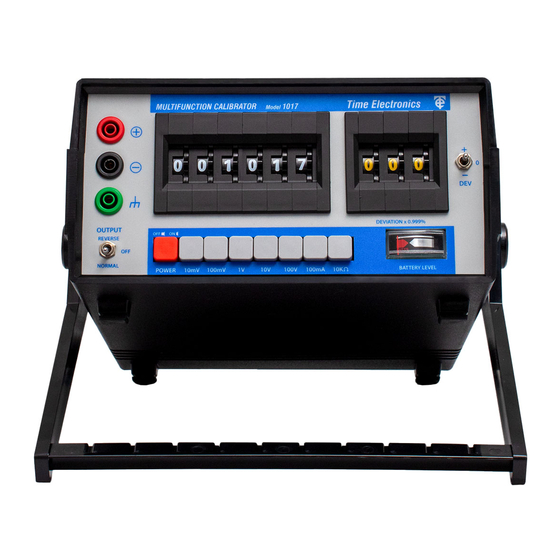
A high-performance portable multifunction calibrator with voltage, current, and resistance ranges. The 1017 combines precision with simple operation, making it suitable for use in the laboratory or field. Constructed in a compact and durable plastic case with a tilt stand/carry handle it takes up minimal bench space and is easily transportable. -
Page 5: Specifications
Output polarity can be selected by a switch on the front panel. Power supply ......The 1017 can be powered continuously from a 230 V 50/60 Hz (110 V to order) main supply, or from the internal rechargeable NiMH battery pack. -
Page 6: Circuit Description
To ensure complete reliability of the thumbwheel switch, double pole gold plated contacts are used for each position – even if a contact fails, the 1017 will continue to work correctly. Power Supply Description The power supply employed in the 1017 is a Time Electronics design type PU2. -
Page 7: Front Panel Controls
Time Electronics 1017 DC Multifunction Calibrator User Manual Front Panel Controls 1 – Output Terminals. 2 – Case Terminal. 3 – Reverse / Off / Normal Switch. Selects the output polarity. 4 – Power On / Off Switch. Indication is shown by the Battery Level Indicator. -
Page 8: Operation
Operation Preparing for Use If using the 1017 unplugged from a mains supply, you must first check the battery level. The battery level is continuously monitored on a front panel LED indicator which also serves as a supply on-off indication. When green the unit is powered on and battery level is good. When red, the batteries need recharging. -
Page 9: Using The 1017
Time Electronics 1017 DC Multifunction Calibrator User Manual Using the 1017 1. Set the correct function and range from the selection buttons. Ensure that the output polarity switch is ’OFF’ and that nothing is dialled up on the digit switch. -
Page 10: Thermal Emf's
User Manual Thermal EMF's When using the 1017 to provide a precision voltage of less than 1mV, care must be taken to avoid Thermal EMF’s. These occur where temperature differences are present at the junctions of dissimilar metals, e.g. – A normal solder to copper junction has a thermal EMF of approximately 3 µV/°C. -
Page 11: Calibration
The 1017 can be calibrated with a high accuracy D.M.M. with D.C. voltage, current and resistance ranges with a specification of at least 4 times greater than that of the 1017’s specifications. Calibration is best carried out on fully charged batteries without the mains supply connected to ensure that no mains supply interference takes any effect on the readings. -
Page 12: Calibrating The Full Scales
Time Electronics 1017 DC Multifunction Calibrator User Manual Calibrating the Full Scales After checking the zero settings you may then calibrate the full scales. Set the digit switch to ’999999’. Select 1 V range: Adjust the 1 V Full Scale with the ’CAL’ trimmer which is on the potted module. -
Page 13: Warranty And Servicing
Online: Please visit www.timeelectronics.com and select Technical Support from the Contact links. From this page you will be able to send information to the Time Electronics service team who will help and support you. By phone: +44 (0) 1732 355993 By email: mail@timeelectronics.co.uk... - Page 14 User Manual Returning Instruments Prior to returning your product please contact Time Electronics. We will issue a return merchandise authorization (RMA) number that is to accompany the goods returning. Further instructions will also be issued prior to shipment. When returning instruments, please ensure that they have been adequately packed, preferably in the original packing supplied.
Need help?
Do you have a question about the 1017 and is the answer not in the manual?
Questions and answers