Advertisement
Quick Links
Advertisement

Related Manuals for Time Electronics 1018


Summary of Contents for Time Electronics 1018
- Page 1 1018 Multi Function V I R DC Calibrator Technical Manual Time Electronics Limited Botany Industrial Estate, Tonbridge, Kent, TN9 1RH Tel: +44(0) 1732 355993 Fax: +44(0)1732 770312 Email: mail@timeelectronics.co.uk Web Site: www.timeelectronics.co.uk V6 17/12/03...
-
Page 2: Table Of Contents
Page Introduction Specifications Circuit and Power Supply Description Front Panel Controls Operation Calibration Guarantee & Service All Time Electronics’ instruments are subject to continuous development and improvement and in consequence may incorporate minor detail changes from the information contained herein. -
Page 3: Introduction
Null Measure This function enables the 1018 to be used as a high performance differential voltmeter to resolve differences as small as 1 micro-volt. An edgewise meter on the front panel indicates the null signal(difference), and zero and sensitivity adjust controls are provided for adjustment. -
Page 4: Specifications
Sensitivity: Max 1uV. Min 200mV fsd. Input R:>1Mohm. Rem o/p +/-200mV Power Supply The 1018 can be powered continuously from a 230V 50/60 Hz (110V to order) mains supply, or from the internal rechargeable battery pack. A front panel LED indicates when the batteries are low. -
Page 5: Circuit And Power Supply Description
The power supply can be set for 220V or 240V AC 50/60 Hz. A 115V version is available to order. The front panel ‘LOW BATT’ LED is illuminated when the batteries are OK and gradually fades as the batteries discharge. The 1018 will operate correctly until the LED goes out. -
Page 6: Front Panel Controls
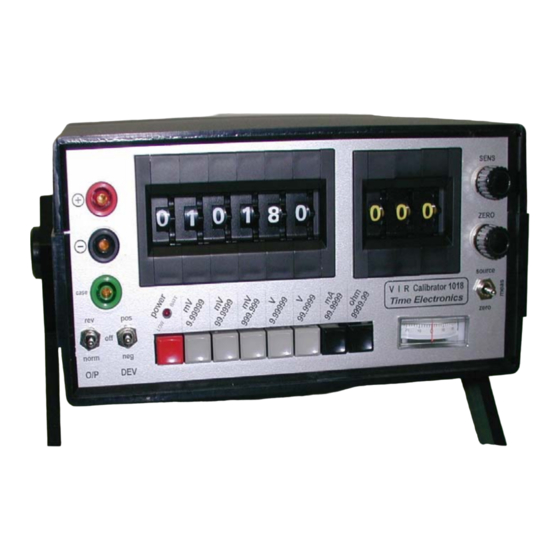
4. Front Panel Controls Page 6 Output Terminals - positive / negative / case Output switch - reverse / off / normal POWER Switch Range Select Switches Output Digit Switch. Selects the value of output Deviation Digit Switch. Selects the value of deviation Battery LED. -
Page 7: Operation
LED being fully lit. If it is dim or not lit you must recharge the batteries by plugging the unit into the mains supply. It will take approximately 12 – 14 hours to fully recharge the battery pack. However, the 1018 may used while it is connected to the mains supply, irrespective of the battery state. - Page 8 Page 8 Null Operation Due to the extreme sensitivity of the electronic null detector it is important to ensure that it is correctly zeroed before attempting accurate measurements. Zero setting procedure: Set function switch to ZERO. Set RANGE switch to required position. Sensitivity (SENS) to maximum (fully clockwise).
-
Page 9: Calibration
Once the screws have been removed place the 1018 on a flat surface, the top section of the cover can then be eased off and the rear panel/power supply can be moved back to allow access to the calibration trimmers which are shown on the diagram below. - Page 10 Page 10 Calibration sequence A high performance DMM is required for the calibration. Time Electronics’ 5075 or equivalent is suitable. Source Function Calibration: Select ’source’ on the Function switch Select ’off’ on the Deviation switch Set all Deviation digit switches to zero 1V range zero: Select 999.999mV range.
- Page 11 This completes the Source Function calibration. Measure function: There is no calibration required for this section of the 1018. However, if required the bal- ance of the null voltage zero can be adjusted using a trimmer located on the null mod- ule.
-
Page 12: Guarantee & Service
Time Electronics Limited Botany Industrial Estate, Tonbridge, Kent, TN9 1RH Tel: +44(0) 1732 355993 Fax: +44(0)1732 770312 Email: mail@timeelectronics.co.uk...
Need help?
Do you have a question about the 1018 and is the answer not in the manual?
Questions and answers