Table of Contents
Advertisement
Quick Links
Operating Manual
Translation of the original operating manual
MKF (E4)
Alternating climate chambers with program control
Model
Model version
MKF 56
MKF056-230V
MKF056-240V
BINDER GmbH
Address: Post office box 102, 78502 Tuttlingen, Germany Phone: +49 7462 2005 0
Fax: +49 7462 2005 100 Internet: http://www.binder-world.com
E-mail: info@binder-world.com Service Hotline: +49 7462 2005 555
Service Fax: +49 7462 2005 93 555 Service E-Mail: service@binder-world.com
Service Hotline USA: +1 866 885 9794 or +1 631 224 4340 x3
Service Hotline Asia Pacific: +852 390 705 04 or +852 390 705 03
Service Hotline Russia and CIS: +7 495 988 15 16
Issue 08/2016
Art. No.
9020-0317
9020-0396
Art. No. 7001-0322
Advertisement
Table of Contents

Related Manuals for Binder MKF 56 Series


Summary of Contents for Binder MKF 56 Series
- Page 1 Fax: +49 7462 2005 100 Internet: http://www.binder-world.com E-mail: info@binder-world.com Service Hotline: +49 7462 2005 555 Service Fax: +49 7462 2005 93 555 Service E-Mail: service@binder-world.com Service Hotline USA: +1 866 885 9794 or +1 631 224 4340 x3 ...
-
Page 2: Table Of Contents
Connection kit for connecting the chamber’s freshwater connection to a water pipe ....... 26 Safety kit: Hose burst protection device with reflux protection device for the chamber’s freshwater connection (available via BINDER INDIVIDUAL customized solutions) ........... 27 Electrical connection ......................... 29 FUNCTIONAL OVERVIEW OF THE MB2 CHAMBER CONTROLLER .... - Page 3 START UP ......................40 Turning on the chamber ........................40 Controller settings upon start up ....................... 41 Turning on/off humidity control ......................42 SET-POINT ENTRY IN “FIXED VALUE” OPERATING MODE ......42 Set-point entry for temperature, humidity, and fan speed through the “Setpoints” menu ....43 Direct setpoint entry for temperature and humidity via Normal display ..........
- Page 4 11. NOTIFICATION AND ALARM FUNCTIONS ............69 11.1 Notification and alarm messages overview ..................69 11.1.1 Notifications ..........................69 11.1.2 Alarm messages ........................70 11.1.3 Messages concerning the humidity system ................70 11.2 State of alarm ............................ 71 11.3 Resetting an alarm, list of active alarms ................... 71 11.4 Activating / deactivating the audible alarm (alarm buzzer) ...............
- Page 5 22.2.1 Cleaning ..........................116 22.2.2 Decontamination ........................117 22.3 Sending the chamber back to BINDER GmbH ................118 23. DISPOSAL ......................119 23.1 Disposal of the transport packing ....................119 23.2 Decommissioning ..........................119 23.3 Disposal of the chamber in the Federal Republic of Germany ............119 23.4 Disposal of the chamber in the member states of the EU except for the Federal Republic of...
-
Page 6: Safety
Understanding and observing the instructions in this operating manual are prerequisites for hazard-free use and safety during operation and maintenance. In no event shall BINDER be held liable for any dam- ages, direct or incidental arising out of or related to the use of this manual. -
Page 7: Safety Alert Symbol
WARNING Indicates a potentially hazardous situation which, if not avoided, could result in death or serious (irre- versible) injury CAUTION Indicates a potentially hazardous situation which, if not avoided, may result in moderate or minor (reversible) injury CAUTION Indicates a potentially hazardous situation which, if not avoided, may result in damage to the product and/or its functions or of a property in its proximity. -
Page 8: Word Message Panel Structure
Prohibition signs Do NOT spray with Do NOT touch Do NOT climb water Information to be observed in order to ensure optimum function of the product. 1.2.4 Word message panel structure Type / cause of hazard. Possible consequences. ∅ Instruction how to avoid the hazard: prohibition ... - Page 9 Figure 1: Position of labels on the chamber Keep safety labels complete and legible. Replace safety labels that are no longer legible. Contact BINDER service for these replacements. MKF+ MKFT (E3.2) 05/2016 page 9/140...
-
Page 10: Type Plate
78532 Tuttlingen / Germany www.binder-world.com Figure 2: Type plate (example of MKF 56 regular unit 230 V) Indications of the type plate (example) Information BINDER Manufacturer: BINDER GmbH MKF 56 Model designation Alternating climate chamber Device name Serial No. 00-00000 Serial no. -
Page 11: General Safety Instructions On Installing And Operating The Chamber
213-850 on safe working in laboratories (formerly BGI/GUV-I 850-0, BGR/GUV-R 120 or ZH 1/119, issued by the employers’ liability insurance association) (for Germany). BINDER GmbH is only responsible for the safety features of the chamber provided skilled electricians or qualified personnel authorized by BINDER perform all maintenance and repair, and if components relat- ing to chamber safety are replaced in the event of failure with original spare parts. - Page 12 The chambers were produced in accordance with VDE regulations and were routinely tested in accord- ance to VDE 0411-1 (IEC 61010-1). CAUTION The window, the access ports and the inner chamber will become hot during opera- tion. Danger of burning. ∅...
-
Page 13: Intended Use
Such ingredients include in particular acids and halides. Any corrosive damage caused by such ingredients is excluded from liability by BINDER GmbH. In case of foreseeable use of the chamber there is no risk for the user through the integration of the chamber into systems or by special environmental or operating conditions in the sense of EN 61010- 1:2010. -
Page 14: Measures To Prevent Accidents
Measures to prevent accidents The operator of the chamber must observe the following rule: “Betreiben von Arbeitsmitteln. Betreiben von Kälteanlagen, Wärmepumpen und Kühleinrichtungen“ (Operation of work equipment. Operation of refrigeration systems, heat pumps and refrigeration equipment) (GUV-R 500 chap. 2.35) (for Germany). The manufacturer took the following measures to prevent ignition and explosions: •... -
Page 15: Resistance Of The Humidity Sensor Against Harmful Substances
Resistance of the humidity sensor against harmful substances The following list of harmful substances refers only to the humidity sensor and does not include any other materials incorporated in the chamber or prohibited substances in relation to explosion protection. Some gases - especially clean gases - do not have any influence on the humidity sensor. Others do have a very small influence, whereas others may influence the sensor to a larger extent. -
Page 16: Chamber Description
A resistance humidifying system humidifies the air. For this purpose, use deionized (demineralized) wa- ter. The option BINDER Pure Aqua Service permits using the chamber with any degree of water hard- ness. -
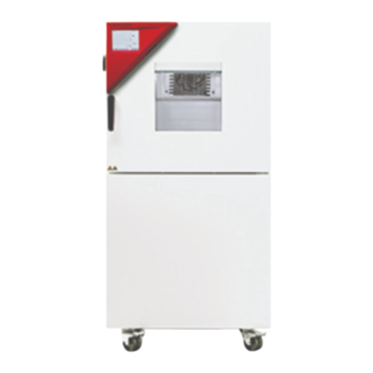
Page 17: Chamber Overview
Chamber overview Figure 3: Alternating climate chamber MKF 56 Instrument panel Door handle Window Door Refrigeration / humidity module 2.2 Instrument panel 5,7" controller display with touchscreen USB interface Pilot lamp Figure 4: Instrument panel with MB2 program controller and USB interface MKF+ MKFT (E3.2) 05/2016 page 17/140... -
Page 18: Lateral Control Panel
Lateral control panel (4a) (4b) (10) Figure 5: Lateral control panel at the right side of the humidity module with options Main power switch ON/OFF Reset switch for over and under temperature safety device class 2 (option) Switch for water cooling (option) Temperature safety device class 2 for over and under temperature (option): Entry displays for upper (4a) and lower (4b) temperature limit Ethernet interface for computer communication... -
Page 19: Rear Chamber View
Rear chamber view (14) (15) (16) (17) (18) (20) (19) Figure 6: Rear view of MKF 56 with water connections and optional water cooling (14) Wastewater connection “OUT” with hose olive for hose ½“ (15) Freshwater connection “IN” with screw thread ¾’’ for hose ½“, with union nut (16) Connection “OUT”... -
Page 20: Main Power Switch
Main power switch Figure 7: Main power switch (1) in the lateral control panel Completeness of delivery, transportation, storage, and installa- tion Unpacking, and checking equipment and completeness of delivery After unpacking, please check the chamber and its optional accessories, if any, based on the delivery receipt for completeness and for transportation damage. -
Page 21: Guidelines For Safe Lifting And Transportation
• If the steam humidifying system has NOT been emptied: +3 °C / 37.4 °F to +60 °C / 140 °F. • After BINDER Service has emptied the steam humidifying system: -10 °C / 14 °F to +60 °C / 140 °F. -
Page 22: Storage
• If the steam humidifying system has NOT been emptied: +3 °C / 37.4 °F to +60 °C / 140 °F. • After BINDER Service has emptied the steam humidifying system: -10 °C / 14 °F to +60 °C / 140 °F. -
Page 23: Location Of Installation And Ambient Conditions
Location of installation and ambient conditions Set up the chamber on a flat, even and non-flammable surface, free from vibration, and in a well- ventilated, dry location and align it using a spirit level. The site of installation must be capable of support- ing the chamber’s weight (see technical data, chap. -
Page 24: Installation And Connections
1 µS/cm (ultrapure water), may cause acid corrosion due to its low pH.) • Water treated by the optional water treatment system BINDER Pure Aqua Service (disposable sys- tem). A reusable measuring equipment to assess the water quality is included (chap. 21.8). -
Page 25: Automatic Fresh Water Supply For Humidifying System Via Water Pipe
BINDER GmbH is NOT responsible for the water quality at the user’s site. Any problems and malfunctions that might arise following use of water of deviating quality is excluded from liability by BINDER GmbH. The warranty becomes void in the event of use of water of deviating quality. -
Page 26: Connection Of Cooling Water Inlet For Water Cooling (Option)
• pH value 4-7 • connection pressure: 4 to 10 bar BINDER GmbH is NOT responsible for the water quality at the user’s site. Any problems and malfunctions that might arise following use of water of deviating quality is excluded from liability by BINDER GmbH. -
Page 27: Safety Kit: Hose Burst Protection Device With Reflux Protection Device For The Chamber's Freshwater Connection (Available Via Binder Individual Customized Solutions)
Safety kit: Hose burst protection device with reflux protection device for the chamber’s freshwater connection (available via BINDER INDIVIDUAL customized solutions) A safety kit with a reflux protection device is available for protection of the drinking water system and against flooding caused by burst water hoses. - Page 28 Assembly: The standard supplied parts – hose burst protection device, hose nozzle with screwing – are not needed. Screw the pre-mounted assembly of the hose burst protection and reflux protection devices onto a water tap with a G¾ inch right turning thread connection. The connection is self-sealing. Establish the connec- tion between the safety kit and the chamber with a part of the supplied hose.
-
Page 29: Electrical Connection
VDE directives (for Germany). We recommend the use of a residual current circuit breaker. • Only use original connection cables from BINDER • Pollution degree (acc. to IEC 61010-1): 2 • Over-voltage category (acc. to IEC 61010-1): II CAUTION Danger of incorrect power supply voltage. -
Page 30: Functional Overview Of The Mb2 Chamber Controller
You can enter values or programs directly at the controller or use the APT-COM™ 3 DataControlSystem software (option) specially developed by BINDER. Operating mode Temperature values... -
Page 31: Operating Functions In Normal Display
Operating functions in normal display Current operating mode Text list for information icons Date, time, authorization level of the logged-in user, memory Quick setpoint entry Continue to next screen Back to Normal display Information Program start Setpoint entry Event list Display of active alarms Access to main menu Figure 12: Operating functions of the MB2 controller in normal display (example values) -
Page 32: Display Views: Normal Display, Program Display, Chart-Recorder Display
Display views: Normal display, program display, chart-recorder display Press the Change view icon to toggle between normal display, program display and chart- recorder display. Press the Normal display icon to return from program display and chart recorder display back to Normal display. -
Page 33: Controller Icons Overview
Controller icons overview Navigation icons in Normal display Icon Signification Function Access from Normal display to the main menu Main menu Access from Normal display to the list of active alarms Alarm Event list Access from Normal display to the event list Access from Normal display to the setpoint entry menu: setpoint Setpoint setting entry for Fixed value operation, turning on/off humidity control,... - Page 34 Functional icons in the chart recorder display Icon Signification Function Show legend Show legend Hide legend Hide legend Switch between legend pages Switch legend Show indication “Door open” (B1), “Anti-condensat.” (B2) and “Com- Show indications pressed air” (B3) Hide indication “Door open” (B1), “Anti-condensat.” (B2) and “Com- Hide indications pressed air”...
-
Page 35: Operating Modes
Operating modes The MB2 program controller operates in the following operating modes: • Idle mode The controller is not functional, i.e., there is no heating or refrigeration and no humidification or dehu- midification. The fan is off. The chamber approximates ambient values. You can activate and deactivate this operating mode with the “Idle mode”... -
Page 36: Controller Menu Structure
Controller menu structure Use the navigation icons in the screen footer in Normal display to access the desired controller func- tions. The available functions depend on the current authorization level “Service”, “Admin” or “User” (chap. 13.1). This is selected either during login or can be available without password protection. Main menu: program settings, further information, “Service”... -
Page 37: Main Menu
• Access to service data, controller reset to factory settings (chap. 5.5.3) • Available only for users with “Service” and “Admin” authorization level. Full functional range only for BINDER Service (users with “Service” authorization level). “Programs” submenu • Access to the controller’s program functions (chap. 8, 9, 10) MKF+ MKFT (E3.2) 05/2016... -
Page 38: Settings" Submenu
Back to main menu 5.5.3 “Service” submenu The “Service” submenu is available for users with “Service” or “Admin” authorization level. When logged- in with “Admin” authorization level the user will find information to tell the BINDER Service in service case. Path: Main menu >... -
Page 39: Principle Of Controller Entries
Principle of controller entries In the selection and entry menus there are icons displayed in the footers which you can use to take over the entry or cancel it. Selection menu (example) Entry menu (example) After completing the settings there are the following possibilities: Press the Confirm icon to take over the entries and exit the menu or continue the menu se- quence. -
Page 40: Performance When Opening The Door
Performance when opening the door When you open the door the fan starts running with minimum speed. After 60 seconds from opening the door, heating, refrigeration, humidification, dehumidification and fan turn off. The compressor continues operating during 5 minutes without cooling function. After closing the door, heating, refrigeration, humidification, dehumidification and fan turn on again. -
Page 41: Controller Settings Upon Start Up
Controller settings upon start up The window “Language selection” enables the language selection, in case that it’s activated in the “Start-up” menu. Afterwards occurs a request of the time zone and the temperature unit. The controller will function in the operating mode, which was active before the last shut-down. It controls temperature in fixed value operating mode to the last entered values and in the program mode to the set points achieved beforehand. -
Page 42: Turning On/Off Humidity Control
Turning on/off humidity control Turning off humidity control is required when operating the chamber without water connection in order to avoid humidity alarms. For further information see chap. 17. Press the Setpoint setting icon to access the “Setpoint” setting menu from Normal display. “Setpoints”... -
Page 43: Set-Point Entry For Temperature, Humidity, And Fan Speed Through The "Setpoints" Menu
With set-point type “Limit”, adapt the safety controller (chap. 12.2) or the over/under tempera- ture safety device class 2 (option, chap. 12.3) always when you changed the temperature set- point. Set the safety controller set-point or the set-point of the over/under temperature safety device class 3.3 (option) by approx. -
Page 44: Direct Setpoint Entry For Temperature And Humidity Via Normal Display
Direct setpoint entry for temperature and humidity via Normal display Alternatively you can also enter the setpoints directly via Normal display. Normal display. Example: “Temperature” entry menu. Select the setpoint you want to change. Enter the desired setpoint and confirm entry with Confirm icon Special controller functions via operation lines Press the Setpoint setting icon to access the “Setpoint”... -
Page 45: Timer Program: Stopwatch Function
Activated operation line: switching status “1” (On) Deactivated operation line: switching status “0” (Off) The operation lines count from right to left. Example: Activated operation line “Humidity off” = 000000000000000 Deactivated operation line “Humidity off” = 000000000000000 Timer program: stopwatch function During an entered duration the controller constantly equilibrates to the setpoints entered in Fixed value operation mode (temperature, humidity, fan speed, configuration of the operation lines). -
Page 46: Stopping A Running Timer Program
Stopping a running timer program 8.2.1 Pausing a running timer program Press the Program pause icon to interrupt the program. The program is paused. The program runtime stops running down, the time display flashes. There are the following options: Press the Program start icon to continue the program Press the Cancelling icon to cancel the program 8.2.2 Cancelling a running timer program Press the Program cancelling icon to cancel the program. -
Page 47: Time Programs
Time programs The MB2 program controller permits programming time programs with real-time reference. It offers 25 program memory positions with up to 100 program sections each. For each program section you can enter a temperature set-point, fan speed, section duration, type of temperature transition (ramp or step) and the tolerance range. -
Page 48: Performance During Program Delay Time
9.1.1 Performance during program delay time During the configured program delay time until program start, the controller equilibrates to the current setpoints of Fixed value operation mode. Modifications of these setpoints are effective. When the config- ured moment for program start is reached, the program delay time ends and the program starts running. Stopping a running time program 9.2.1 Pausing a running time program Press the Program pause icon to interrupt the program.. -
Page 49: Creating A New Time Program
Creating a new time program Path: Main menu > Programs > Time program “Time program” menu: Enter the program name and, if desired, addi- overview of the existing programs. tional program information in the corresponding fields. Select an empty program place. Press the Confirm icon. -
Page 50: Deleting A Time Program
Program editor: “Edit program” menu Select the desired function and press the Confirm icon. The program editor offers following options: • Change the program name • Copy program • Replace program: Replacing an new or an existing program with the copied program. This menu point is visible only after a program has been copied. -
Page 51: Section Editor: Section Management
Section editor: section management Path: Main menu > Programs > Time program Select the desired program. Program view. Section view (example: section 1). Select the desired program section There are the following options: (example: section 1) Select a parameter to enter or modify the according value (chap. -
Page 52: Add A New Program Section
9.6.1 Add a new program section Section editor: “Edit section” menu. Select “Add new section” and press the Confirm icon. Then select whether to insert the new section before or after the current section. Press the Confirm icon. The new section opens. 9.6.2 Copy and insert or replace a program section Program view. -
Page 53: Deleting A Program Section
Press the Edit icon to open the section editor if you want the current section to be replaced or the copied section to be inserted before or after it Program view. Section view (example: section 1). Select the section to be replaced or before or Press the Edit icon to open the section editor after which the copied section shall be insert- ed (example: section 2) and press the Con-... -
Page 54: Value Entry For A Program Section
Value entry for a program section Path: Main menu > Programs > Time program Select the desired program and section. The section view gives access to all parameters of a program section. You can enter or modify the val- ues. Program name and section number Section duration Type of setpoint transition: ramp or step... -
Page 55: Set-Point Ramp And Set-Point Step
9.7.2 Set-point ramp and set-point step You can define the type of temperature and humidity transitions for each individual program section. “Ramp” mode: Gradual changes of temperature and humidity The set-point of a given program section functions as the section’s start temperature. During the section’s duration, the set-point gradually passes to the set-point of the subsequent program section. -
Page 56: Special Controller Functions Via Operation Lines
“Ramp” and “Step” mode example (representation of a temperature course) W/°C t/min. Corresponding program table Duration Temperature Humidity Section No. Ramp or Step [hh:mm:ss] [°C] [% rH] 00:10:00 40.0 xxxx xxxx Step 00:20:00 60.0 xxxx xxxx Step 00:10:00 80.0 xxxx xxxx Step 00:20:00... -
Page 57: Setpoint Entry
Use the Section editor to configure the operation lines. Section view. “Functions on/off” entry menu. Select the field “Functions on/off”. Mark / unmark the checkbox of the desired function to activate / deactivate it and press the Confirm icon. The controller returns to the section view. Activated operation line: switching status “1”... -
Page 58: Tolerance Range
9.7.5 Tolerance range You can specify a temperature and humidity program tolerance range for each program section with dif- ferent values for the tolerance minimum and maximum. When the actual value exceeds the given thresh- old, the program is interrupted. This is indicated on the display (see below). When the actual temperature is situated again within the entered tolerance limits, the program automatically continues. -
Page 59: Repeating One Or Several Sections Within A Time Program
9.7.6 Repeating one or several sections within a time program You can repeat individual sections or several subsequent sections together. Enter the desired number of repetitions in the field „Number of repetitions“ and the number of the section to start the repetition cycle with in the field “Start section for repetition” To have sections repeated infinite- ly, enter the number of repetitions as “-1”. -
Page 60: Week Programs
Week programs The MB2 program controller permits programming week programs with real-time reference. It offers 5 week program places in total with up to 100 shift points for each week program. Path: Main menu > Programs> Week program 10.1 Starting an existing week program In Normal display press the Program start icon to access the “Program start”... -
Page 61: Creating A New Week Program
10.3 Creating a new week program Path: Main menu > Programs > Week program Enter the program name and, if desired, addi- “Week program” menu: tional program information in the correspond- overview of the existing programs. ing fields. Select an empty program place. Press the Confirm icon. -
Page 62: Program Editor: Program Management
10.4 Program editor: program management Path: Main menu > Programs > Week program “Week program” menu: Program view (example: program 1). overview of the existing programs. If a new program has been created, there is Select an existing program just one program section. -
Page 63: Deleting A Week Program
To add a new section, select “Add new sec- Program view. tion” and press the Confirm icon. With a new section no weekday is specified. There- The program view opens. fore the section is first marked in red and cannot be saved. -
Page 64: Section Editor: Section Management
10.5 Section editor: section management Path: Main menu > Programs > Week program Select the desired program. Section view (example: section 1). Program view. There are the following options: Select the desired program section (example: section 1) ... -
Page 65: Add A New Program Section
10.5.1 Add a new program section Section editor: “Edit section” menu. Program view. With a new section no weekday is specified. There- Select “Add new section” and press the Con- fore the section is first marked in red and cannot be firm icon. -
Page 66: Deleting A Program Section
Select “Replace section” to replace the selected sec- tion with the copied section Select “Insert section” to additionally add the copied section. Press the Confirm icon. If you selected “Insert section” the sections are auto- matically arranged in the correct chronological order. Section editor: “Edit section”... -
Page 67: Weekday
10.6.2 Weekday In the field “Weekday” select the desired weekday. With “Daily” selected, this section will run every day at the same time. Section view. 10.6.3 Start time Section view. Entry menu “Moment”. Select with the arrow keys the desired start Select the field “Moment”. -
Page 68: Setpoint Entry
10.6.4 Setpoint entry • Select the field “Temperature” and enter the desired temperature setpoint. Setting range: -50 °C up to 180 °C. Confirm entry with Confirm icon. The controller returns to the section view. • Select the field “Humidity” and enter the desired humidity setpoint. Setting range: 0% r.H. -
Page 69: Notification And Alarm Functions
Notification and alarm functions 11.1 Notification and alarm messages overview 11.1.1 Notifications Notifications are indicated by information icons displayed in the screen header in Normal display An information icon serves as an indication of a certain condition. If this condition persists, in some cases an alarm will be triggered after a fix or configurable interval. As long as the condition persists, the information icon therefore continues to be displayed also in state of alarm. -
Page 70: Alarm Messages
11.1.3 Messages concerning the humidity system Start after condition Condition and measures Message occurred The humidity module is defective. Contact BINDER “Humidity system” immediately service The humidity module cannot fill up. In case of freshwater supply via water pipe: The water tap is closed, or the chamber is defective (e.g. -
Page 71: State Of Alarm
11.2 State of alarm 1. Visual indications in Normal display: alarm message, screen header flashing in red color 2. Audible alert, if the buzzer is enabled (chap. 11.4). Normal display in state of alarm (example). (a) Screen header flashing in red color and showing the alarm message (b) Alarm icon on the bottom of the screen: change to the list of active alarms and... -
Page 72: Activating / Deactivating The Audible Alarm (Alarm Buzzer)
The user cannot restart the device again. The protec- tive cut-off device is located internally. Only a service specialist can replace it. Therefore, please contact an authorized service provider or BINDER service. 12.2 Safety controller (over temperature safety device class 2) The chamber is regularly equipped with an over temperature safety device class 2 acc. -
Page 73: Safety Controller Modes
12.2.1 Safety controller modes You can select between “Limit (absolute)” and “Offset (relative)” safety controller mode • Limit: Absolute maximum permitted temperature value This setting offers high safety as a defined temperature limit will not be exceeded. It is important to adapt the safety controller set-point after each modification of the temperature set-point. -
Page 74: Message And Measures In The State Of Alarm
Regularly check the safety controller setting for set-point type “Limit” or “Offset” • in Fixed value operating mode according to the entered set-point temperature value • in program mode according to the highest temperature value of the selected temperature program Set the safety controller set-point by approx. -
Page 75: Over/Under Temperature Safety Device Class 2 (Option)
12.3 Over/under temperature safety device class 2 (option) The over-/under temperature safety device (4) consists of two entry modules (4a) and (4b) located in the lateral control panel. Both modules can be set from -50 °C / -58 °F up to 200 °C / 392 °F and serve to de- fine the maximum high and low temperature limits. -
Page 76: User Management
• All passwords can be changed in the “log out” submenu (chap. 13.3). “Service” authorization level • Authorization level only for BINDER service • Extensive authorization for controller operation and configuration, access to service data • The passwords for “Service”, “Admin” and “User” authorization levels can be changed in the “log out”... - Page 77 Operation after user login At user login, the authorization level is selected and confirmed by entering the respective pass- word. Following user login, controller operation is avail- able, recognizable by the open-lock icon in the header. The available controller functions corre- spond to the user’s authorization level.
- Page 78 Information window To check the authorization level of the user currently logged-in, select in Normal display the arrow far right in the display header. The information window shows date and time, the controller’s free memory space and under “Authoriza- tion” the authorization level of the current user. If passwords have been assigned for all authorization levels, a user without login (password entry) has no authorization.
-
Page 79: Log In
13.2 Log in Path: Main menu > User > Log in Controller without a user logged-in Selection of user type (example) All selection possibilities are password protected Controller with logged-in user After completing the settings, press the Confirm icon to take over the entries and exit the menu, or press the Close icon to exit the menu without taking over the entries. -
Page 80: Log Out
13.3 Log out Path: Main menu > User > Log out User logoff with “Admin” authorization Controller Controller with without a user logged-in user logged-in User logoff with “Admin” authorization Controller Controller with without a user logged-in user logged-in 13.4 User change If the password function has been deactivated (chap.13.5.2) this function is not available. -
Page 81: Password Assignment And Password Change
User selection (example) All selection possibilities are password protected Controller with logged- in user 13.5 Password assignment and password change This function is not available for a user logged-in with “User” authorization. 13.5.1 Password change A logged-in user can change the passwords of his current level and of the next lower level(s). Example: A user with “Admin”... - Page 82 Selection of the authorization level Enter desired password. If desired, press the Change (example: view with “Admin” authorization) keyboard icon to access other entry windows. In the “Keyboard switch” window you can select different keyboards to enter uppercase and lowercase letters, digits, and special characters.
-
Page 83: Deleting The Password For An Individual Authorization Level
13.5.2 Deleting the password for an individual authorization level A user logged-in with “Service” or “Admin” authorization can delete the passwords of his current level and of the next lower level(s). To do this no password is entered during a password change. Path: Main menu >... -
Page 84: New Password Assignment For "Service" Or "Admin" Authorization Level When The Password Function Was Deactivated
13.5.3 New password assignment for “service” or “admin” authorization level when the password function was deactivated If the password protection for an authorization level has been deactivated, i.e., no password is assigned, no login for this level is possible. Therefore access to this authorization level is available without login. If the password for the “Service”... -
Page 85: Activation Code
13.6 Activation code Certain functions of the controller can be unlocked with a previously generated activation code. The activation code enables access to functions available only in the “Service” authorization level by us- ers without a “Service” authorization. Such functions include e.g., adjustment or extended configurations. The activation code is available in authorization levels. -
Page 86: General Controller Settings
General controller settings Most of the general settings can be accessed in the “Settings” submenu, which is available for users with “Service” or “Admin” authorization level. It serves to enter date and time, select the language for the con- troller menus and the desired temperature unit and to configure the controller’s communication functions. 14.1 Selecting the controller’s menu language The MB2 program controller communicates by a menu guide using real words in German, English, French, Spanish, and Italian. -
Page 87: Setting Date And Time
14.3 Setting date and time Following start-up of the chamber after language selection: Select the time zone and configure the daylight saving time switch. Or later: Path: Main menu > Settings > Date and time “Date and time” submenu. “Date / time” entry menu. Select the field “Date / time”. -
Page 88: Display Configuration
“Date and time” submenu. “Date and time” submenu. Select the desired start of the daylight saving Select the desired end of the daylight saving time. time and press the Confirm icon. After completing the settings, press the Confirm icon to take over the entries and exit the menu, or press the Close icon to exit the menu without taking over the entries. -
Page 89: Touchscreen Calibration
• Select the field “Wait time for screen saver” and enter the desired waiting time for the screen saver in seconds. Setting range: 10 sec up to 32767 sec. During the waiting time the display is off. Confirm entry with Confirm icon. •... -
Page 90: Network And Communication
This menu allows to configure the communication parameters of the RS485 interface. The device address is required to recognize chambers with this interface type in a network, e.g. when connecting it to the optional communication software BINDER APT-COM™ 3 DataControlSystem (chap. 21.1). In this case do not change the other parameters. -
Page 91: Ethernet
14.5.2 Ethernet 14.5.2.1 Configuration Path: Main menu > Settings > Ethernet “Ethernet” submenu. • In the field “IP address assignment” select the desired setting “Automatic (DHCP)“ or “Manual“. With selection “Manual” you can enter the IP- address, the subnet mask and the standard gateway manually. -
Page 92: Web Server
Internet. The IP address is available via Chamber information > Ethernet. The BINDER web server opens. Enter the user name and password which have been assigned for the web server in the controller menu. This enables online access to the controller display, to see e.g., the event list or error messages. -
Page 93: E-Mail
14.5.4 E-Mail As soon as an alarm was triggered, an e-mail is sent to the configured e-mail address. Path: Main menu > Settings > Email E-mail address entry: “Email” submenu. Select the desired e-mail address field and enter the e-mail address. You can use the Keybord change icon for entry. -
Page 94: Data Import / Export Via Usb Medium
14.6 Data import / export via USB medium When you insert a USB-stick, the “USB” menu opens. Depending on the user’s authorization level, different functions (highlighted in black) are available for the logged-in user. Available functions with “User” authorization level Available functions with “Admin”... -
Page 95: Turning Off The Interior Lighting Automatically
14.7 Turning off the interior lighting automatically Press the Interior lighting icon to turn on and off the interior lighting. Additionally. you can define in this menu the interval after which the turned-on light will turn off automati- cally. Path: Main menu >... -
Page 96: Current Operating Parameters
15.2 Current operating parameters Press the Information icon to access the “Info” menu from Normal display. “Info” menu. Select the desired information. • Select “Program operation” to see infor- mation on a currently running program. • Select “Setpoints“ to see information on the entered setpoints and operation lines. -
Page 97: Event List
15.4 Technical chamber information Path: Main menu > Device info Chamber name and setup Versions of CPU, I/O module and safety con- for BINDER troller Service Information on digital and analog inputs and for BINDER outputs and phase angle outputs... -
Page 98: Chart Recorder Display
Chart recorder display This view offers graphic representation of the measurement course. Data representation imitates a chart recorder and allows recalling any set of measured data at any point of time taken from the recorded peri- 16.1 Views Press the Change view icon to access the pen recorder display. 16.1.1 Show and hide legend Show legend Hide legend... -
Page 99: Show And Hide Specific Indications
16.1.3 Show and hide specific indications Show indications Hide indications Press the Show indications icon to display the indications “Door open” (B1), “Anti-condensat.” (B2), “Compressed air” (B3) indications “Door open” (B1), “Anti-condensat.” (B2), “Compressed air” (B3) displayed. 16.1.4 History display History display Press the History display icon to change to the history display. - Page 100 History display: Curve selection Curve selection Press the Curve selection icon to access the “Curve selection” submenu. “Curve selection” submenu. Select the curves to be displayed by checking the checkbox of the corresponding parameter. Press the Confirm icon History display: Search the required instant Search Press the Search icon to access the “Search”...
- Page 101 History display: Zoom function Zoom Press the Zoom icon to access the “Zoom” submenu. “Zoom” submenu. Select the zoom factor and press the Confirm icon History display: Show and hide scroll buttons to scroll to an instant Show scroll buttons Hide scroll buttons Press the Show scroll buttons icon to access the “Page selection”...
-
Page 102: Setting The Parameters
16.2 Setting the parameters This menu allows setting the storage interval, the type of values to be shown and the scaling of the tem- perature and humidity charts. Path: Main menu > Settings > Measurement chart “Measurement chart” submenu. • Select the field “Storage interval” and enter the desired storage interval. Confirm entry with Confirm icon. -
Page 103: Humidification / Dehumidification System
Humidification / dehumidification system The chamber is equipped with a capacitive humidity sensor. This results in a regulatory accuracy of up to +/- 2.5 % r.h. of the set point. The temperature-humidity diagrams (Figure 13) show the possible working range for humidity. •... -
Page 104: Function Of The Humidifying And Dehumidifying System
In climatic operation (with humidity) the preset temperature and humidity values must be situ- ated within range A in order to achieve optimum regulation. In the short-term set points in the discontinuous range (range B) can also be targeted. On the edges of the control range (ranges A + B) the regulatory accuracies of ± 2.5 % r.H. cannot be guaranteed. -
Page 105: Freshwater
• Water intake temperature NOT below +5 °C / 41 °F and not exceeding 40 °C / 104 °F. BINDER GmbH is NOT responsible for the water provided by the customer. Any problems and malfunctions that might arise following use of water of deviating quality is excluded from liability by BINDER GmbH. -
Page 106: Defrosting At Refrigerating Operation
Defrosting at refrigerating operation BINDER alternating climate chambers are very diffusion-proof. To ensure high temperature precision there is no automatic cyclic defrosting device. However, at very low temperatures, the moisture in the air can condense on the evaporator plates leading to icing. -
Page 107: Anti-Condensation Protection Via Operation Line
Anti-condensation protection via operation line The anti-condensation protection condensates the chamber humidity at the coldest point in order to avoid the samples becoming wet from condensation. Anti-condensation protection is performed by the evapora- tor and can be programmed On/Off via operation line “Anti-condensation” in Fixed value and program modes. -
Page 108: Zero-Voltage Switching Outputs Via Operation Lines
Zero-voltage switching outputs via operation lines The operation lines serve to switch any device connected to the zero-voltage relay output (DIN sockets (7) and (8) located in the lateral control panel). They can be programmed On/Off in Fixed value and pro- gram modes. -
Page 109: Options
BINDER Data Loggers are equipped with a keyboard and a large LCD display, alarm functions and a real-time function. Measurement data are recorded in the Data Logger and can be read out after the measurement via the RS232 interface of the Data Logger. -
Page 110: Analog Outputs For Temperature And Humidity (Option)
(air cooling). Retrofitting by the manufacturer is possible: The chamber must be returned to the BINDER factory for installation. You can supply the chamber’s humidity system with freshwater and drain the wastewater via a water pipe or manually with the internal water cans, like with the regular chamber. -
Page 111: Object Temperature Display With Flexible Pt 100 Temperature Sensor (Option)
The object temperature data are put out together with the data of the temperature controller to the Ether- net interface as second measuring channel and can be documented by the communication software APT- COM™ (option, chap. 21.1) developed by BINDER. Technical data of the Pt 100 sensor: •... -
Page 112: Mounting The Freshwater Can
21.7.1 Mounting the freshwater can Fixing (if required) Hang the can with its holding device on its 4 carriers. You can install it either at the left or the right side. Cable connection (21) Freshwater hose connection (22) Figure 18: Freshwater can (option) Cable connections Connect the plug of the cable to the socket (18) at the rear of the chamber. -
Page 113: Mounting The Wastewater Can
21.7.2 Mounting the wastewater can Fixing (if required) Hang the can with its holding device on its 4 carriers at the free space next to the freshwater can. Hose connections Plug the wastewater hose to the hose connection (23) of the wastewater can and secure it with a hose clamp. -
Page 114: Binder Pure Aqua Service (Option)
Regularly check the filling level of the freshwater can. 21.8 BINDER Pure Aqua Service (option) The optional BINDER water treatment system (disposable system) serves to treat tap water. The lifetime depends on water quality and the amount of treated water. The measuring equipment to assess the water quality is reusable. -
Page 115: Maintenance, Cleaning, And Service
(behind the left maintenance access flap) every week. In case of visible dirt accumulation, disconnect the chamber and clean the fan grid by suction. We recommend taking out a maintenance agreement. Please consult BINDER Service. BINDER telephone hotline:... -
Page 116: Cleaning And Decontamination
Any corrosive damage that may arise following use of other cleaning agents is excluded from liability by BINDER GmbH. Any corrosive damage caused by a lack of cleaning, is excluded from liability by BINDER GmbH. CAUTION Danger of corrosion. -
Page 117: Decontamination
For chemical disinfection, we recommend the disinfectant spray Art. No. 1002-0022. Any corrosive damage that may arise following use of other disinfectants is excluded from liability by BINDER GmbH. With every decontamination method, always use adequate personal safety controls. MKF+ MKFT (E3.2) 05/2016... -
Page 118: Sending The Chamber Back To Binder Gmbh
22.3 Sending the chamber back to BINDER GmbH If you return a BINDER product to us for repair or any other reason, we will only accept the product upon presentation of an authorization number that has previously been issued to you. An authorization num- ber (RMA number) will be issued after receiving your complaint either in writing or by telephone prior to your sending the BINDER product back to us. -
Page 119: Disposal
According to Annex I of Directive 2012/19/EU of the European Parliament and of the Council on waste electrical and electronic equipment (WEEE), BINDER devices are classified as “monitoring and control instruments” (category 9) only intended for professional use“. They must not be disposed of at public col- lecting points. - Page 120 (Elektro- und Elektronikgerätegesetz, ElektroG from 20 Octo- ber 2015, BGBl. I p. 1739) or contact BINDER service who will organize taking back and disposal of the chamber according to the German national law for electrical and electronic equipment (Elektro- und El- ektronikgerätegesetz, ElektroG from 20 October 2015, BGBl.
-
Page 121: Disposal Of The Chamber In The Member States Of The Eu Except For The Federal Republic Of Germany
According to Annex I of Directive 2012/19/EU of the European Parliament and of the Council on waste electrical and electronic equipment (WEEE), BINDER devices are classified as “monitoring and control instruments” (category 9) only intended for professional use“. They must not be disposed of at public col- lecting points. -
Page 122: Disposal Of The Chamber In Non-Member States Of The Eu
23.5 Disposal of the chamber in non-member states of the EU CAUTION Alteration of the environment. For final decommissioning and disposal of the chamber, please contact BINDER ser- vice. Follow the statutory regulations for appropriate, environmentally friendly disposal. - Page 123 Safety controller set too low. select suitable safety controller turned on. setpoint (chap. 12.2). Safety controller responds. Safety controller (chap. 12.2) defec- Contact BINDER service. tive. Nominal temperature exceeded by 20 Chamber permanently turned °C due to chamber failure. Over tem- Contact BINDER service.
- Page 124 > Select cooler place of installa- Place of installation too hot. 1 °C with a set-point approx. 3 tion or contact BINDER service. °C above ambient temperature. Capillary tube blocked. No or low dehumidification. Contact BINDER service.
-
Page 125: Technical Description
The chambers were calibrated and adjusted in the factory. Calibration and adjustment were performed using standardized test instructions, according to the QM DIN EN ISO 9001 system applied by BINDER (certified since December 1996 by TÜV CERT). All test equipment used is subject to the administration of measurement and test equipment that is also constituent part of the BINDER QM DIN EN ISO 9001systems. -
Page 126: Definition Of Usable Volume
25.3 Definition of usable volume The usable volume illustrated below is calculated as follows: A, B, C = internal dimensions (W, H, D) a, b, c = wall separation a = 0.1*A b = 0.1*B c = 0.1*C = (A - 2 * a) * (B - 2 * b) * (C - 2 * c) Figure 21: Determination of the useable volume The technical data refers to the defined usable volume. - Page 127 +22 °C ± 3 °C / 71.6 °F ± 5.4 °F and a power supply voltage fluctuation of +/-10%. Technical data is determined in accordance to BINDER Factory Standard Part 2:2015 and DIN 12880:2007. All indications are average values, typical for chambers produced in series. We reserve the right to change technical specifications at any time.
-
Page 128: Equipment And Options (Extract)
Lockable door Communication interface RS485 BINDER Data Logger kit for temperature T 220 (chamber values), for temperature / humidity TH 100 (chamber values) or TH 100/70 (chamber and ambient values) Safety kit for water connection with hose burst protection device and reflux protection device, pre-... -
Page 129: Accessories And Spare Parts (Extract)
25.6 Accessories and spare parts (extract) BINDER GmbH is responsible for the safety features of the chamber only, provided skilled electricians or qualified personnel authorized by BINDER perform all maintenance and repair, and if components relating to chamber safety are replaced in the event of failure with original spare parts. -
Page 130: Dimensions Mk 56
25.7 Dimensions MK 56 MKF+ MKFT (E3.2) 05/2016 page 130/140... -
Page 131: Certificates And Declarations Of Conformity
Certificates and declarations of conformity 26.1 EU Declaration of Conformity MKF+ MKFT (E3.2) 05/2016 page 131/140... - Page 132 MKF+ MKFT (E3.2) 05/2016 page 132/140...
- Page 133 MKF+ MKFT (E3.2) 05/2016 page 133/140...
-
Page 134: Product Registration
Product registration MKF+ MKFT (E3.2) 05/2016 page 134/140... -
Page 135: Contamination Clearance Certificate
Contamination clearance certificate 28.1 For chambers located outside the USA and Canada Declaration regarding safety and health Erklärung zur Sicherheit und gesundheitlichen Unbedenklichkeit The German Ordinance on Hazardous Substances (GefStofV), and the regulations regarding safety at the workplace, require that this form be filled out for all products that are returned to us, so that the safety and the health of our employees can be guaranteed. - Page 136 Kind of transport / transporter / Transportweg/Spediteur: Transport by (means and name of transport company, etc.) Versendung durch (Name Spediteur o.ä.) ___________________________________________________________________________________ Date of dispatch to BINDER GmbH / Tag der Absendung an BINDER GmbH ___________________________________________________________________________________ MKF+ MKFT (E3.2) 05/2016 page 136/140...
- Page 137 We are aware that, in accordance with Article 823 of the German Civil Code (BGB), we are directly liable with regard to third parties, in this instance especially the employees of BINDER GmbH, who have been entrusted with the handling / repair of the unit / component. / Es ist uns bekannt, dass wir gegenüber Dritten –...
-
Page 138: For Chambers Located In The Usa And Canada
Please complete this form and the Customer Decontamination Declaration (next 2 pages) and attach the required pictures. E-mail to: IDL_SalesOrderProcessing_USA@binder-world.com After we have received and reviewed the complete information we will decide on the issue of a RMA number. Please be aware that size specifications, voltage specifications as well as performance specifi- www.binder-world.us... - Page 139 Customer (End User) Decontamination Declaration Health and Hazard Safety declaration To protect the health of our employees and the safety at the workplace, we require that this form is com- pleted by the user for all products and parts that are returned to us. (Distributors or Service Organizations cannot sign this form) NO RMA number will be issued without a completed form.
- Page 140 4.5 Shipping laws and regulations have not been violated. I hereby commit and guarantee that we will indemnify BINDER Inc. for all damages that are a consequence of incomplete or incorrect information provided by us, and that we will indemnify and hold harmless BINDER Inc.
Need help?
Do you have a question about the MKF 56 Series and is the answer not in the manual?
Questions and answers